 | The electrical characteristics are given in paragraph Electrical features. The wiring examples are given in paragraph Connection examples |
|---|
.
| @cnna@ | Terminal | Symbol | Description | Address | ||
|---|---|---|---|---|---|---|
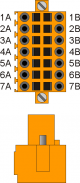 | 1A | Uscita +24V dc1) | ||||
| 2A | PHA1 | Phase A | Count 1 PNP Push-Pull2) | 2.INP17 | 2.CNT01 | |
| 3A | PHB1 | Phase B | 2.INP18 | |||
| 4A | Z1 | Z | 1.INT01 | |||
| 5A | 0V | Common for count inputs | ||||
| 6A | 0V | |||||
| 7A | 0V | |||||
| 1B | +24Vdc out3) | |||||
| 2B | PHA1+ | + PHA | Count 1 Line Driver | 2.INP17 | 2.CNT01 | |
| 3B | PHB1+ | + PHB | 2.INP18 | |||
| 4B | Z1+ | + Z | 1.INT01 | |||
| 5B | PHA1- | - PHA | ||||
| 6B | PHB1- | - PHB | ||||
| 7B | Z1- | - Z | ||||
2)
PNP/Push-Pull type count input configuration:
Terminal 5B: connect to terminal 5A
Terminal 6B: connect to terminal 6A
Terminal 7B: connect to terminal 7A
Terminal 5B: connect to terminal 5A
Terminal 6B: connect to terminal 6A
Terminal 7B: connect to terminal 7A
| @cnnb@ | Terminal | Symbol | Description | Address | ||
|---|---|---|---|---|---|---|
| | 1A | Uscita +24V dc1) | ||||
| 2A | PHA2 | Phase A | Count 2 PNP Push-Pull2) | 2.INP19 | 2.CNT02 | |
| 3A | PHB2 | Phase B | 2.INP20 | |||
| 4A | Z2 | Z | 1.INT02 | |||
| 5A | 0V | Common for count inputs | ||||
| 6A | 0V | |||||
| 7A | 0V | |||||
| 1B | +24Vdc out3) | |||||
| 2B | PHA2+ | + PHA | Count 2 Line Driver | 2.INP19 | 2.CNT02 | |
| 3B | PHB2+ | + PHB | 2.INP20 | |||
| 4B | Z2+ | + Z | 1.INT02 | |||
| 5B | PHA2- | - PHA | ||||
| 6B | PHB2- | - PHB | ||||
| 7B | Z2- | - Z | ||||
2)
PNP/Push-Pull type count input configuration:
Terminal 5B: connect to terminal 5A
Terminal 6B: connect to terminal 6A
Terminal 7B: connect to terminal 7A
Terminal 5B: connect to terminal 5A
Terminal 6B: connect to terminal 6A
Terminal 7B: connect to terminal 7A