Connector
| @cnn@ | Terminal | Symbol | Description | Address | |
|---|---|---|---|---|---|
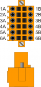 | 1A | VD1 | Internal bridge 1A -1B | ||
| 2A | DIR1+ | Output DIRECTION 1 | Push-Pull Line Driver | @slot@.PULSE01 | |
| 3A | STEP1+ | Output STEP 1 | |||
| 4A | DIR2+ | Output DIRECTION 2 | @slot@.PULSE02 | ||
| 5A | STEP2+ | Output STEP 2 | |||
| 6A | 0V | Common for stepper outputs | |||
| 1B | VD1 | Internal bridge 1A -1B | |||
| 2B | DIR1- | Complementary output DIRECTION 1 | Complementary outputs for use in drives with Line-Driver inputs | ||
| 3B | STEP1- | Complementary output STEP 1 | |||
| 4B | DIR2- | Complementary output DIRECTION 2 | |||
| 5B | STEP2- | Complementary output STEP 2 | |||
| 6B | 0V | Common for stepper outputs | |||
Outputs STEP-DIRECTION voltage setting
By placing one of several jumpers JP5, JP6 and JP7, you can choose Nominal Operating Voltage of STEP and DIRECTION outputs.
 | Must be inserted only one jumper at a time If you select one of the two voltage 5V (JP7) or 12V (JP5) terminals 1A and 1B must remain disconnected |
|---|
.
| jumper name | Setting | Nominal voltage | ||
|---|---|---|---|---|
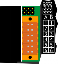 | JP5 | INSERTED | 12V (Voltage supplied by the instrument) | 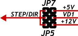 |
| JP6 | INSERTED | VD1 (Voltage to be supplied to the terminals 1A or 1B) | ||
| JP7 | INSERTED | 5V (Voltage supplied by the instrument) | ||