Indice
DEVICE ABSCNT
1. Introduction
The internal ABSCNT device manages the acquisition and manipulation of the position from absolute sensors. These sensors are typically absolute encoders with different types of output interface (parallel, SSI, etc.) The main features of the device are:
-
control of the data quality from the transducer
-
support for binary or gray encoding data
-
sexagesimal representation of read data (angles in degrees and early)
-
internal zero for the absolute position
-
generating an incremental count to be used by other devices
2. Declaration
For use the device you must declare it in the INTDEVICE section of the unit configuration.
;---------------------------------
; Internal devices Declaration
;---------------------------------
INTDEVICE
...
<nome>  ABSCNT  TCamp  IAbsCont  ICont
Dove:
| Field name | Description | Example | Note |
|---|---|---|---|
| <nome> | Device name | Axe | - |
| ANPOS2 | Keyword that identifies the device ABSCNT | - | - |
| TCamp | Device sampling time in milliseconds | 4 | - |
| IAbsCont | Absolute counter number (Verify the HW documentation of the product for the correct value to set) | 1 | |
| ICont | Incremental counter address generated by the device (always 1.CNTx) | 1.CNT01 | If entering the value X. X field is ignored |
 | All fields of the Declaration are mandatory and must be present on the same line. Set “X.X” or “X” if a resource is not available or cannot be used. Disable a resource means disable all functionality of the devices that use it. |
|---|
3. Operation
Operation of the device is illustrated with the following diagram:
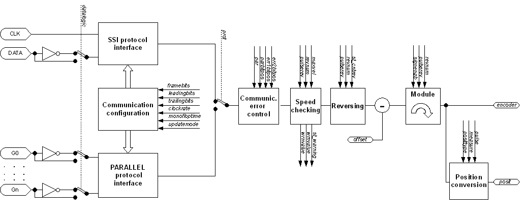
3.1 Communication configuration
The “Communication configuration” block Configure Protocol blocks appropriately in accordance with the number of bits to be captured, with the number of bits to “discard”, with the capture mode, etc.
3.2 SSI protocol interface
The “SSI protocol interface” block executes the acquisition of data from a transducer with SSI protocol. The read data should then be manipulated to get information by absolute position.
3.3 Communication error control
The “Communication error control” block does the control of the “quality” of data acquired by the transducer. Controls can be equal and/or, for transducers that require it, the verification of certain bits of error present in the frame.
3.4 Speed checking
The “Speed checking” block check the rotational speed in RPM compared to the maximum and shall report any overshoot. His task is to detect errors in the acquisition of the data.
3.5 Reversing
The “Reversing” block manages the reversal of direction of rotation that causes the increase in location determined byst_cntdir.
3.6 Module
The “Module” block manipulates the position acquired and subtracts the offset to bring it back within the range 0÷(pulserev x revnum) quando signenab be worth 0 and within the range -(pulserev x revnum)/2 ÷ (pulserev x revnum)/2 when signenab be worth 1.
3.7 Position conversion
The “Position conversion” block converts from value bits position at value position in units of measurement. The data obtained (posit) can have decimal or sexagesimal representation depending on the setting parameter posittype.
4. Notes on the device operation
-
It is possible to use the device for generating a virtual counter by setting the address ICont on the device declaration; because is the “virtual” counter you will always find in slot 1 (CPU ID). This feature makes it possible to use a translator of absolute type with counting and positioning devices that use incremental translators only (hardware resource CNTxx). Important: the “virtual” counter will update each device or sampling every 1ms depending on the setting of the parameter value updatemode.
-
When you set the sexagesimal representation the two least significant digits of the parameter posit indicate the 'minute', the other indicate the 'degrees'. With the sexagesimal representation, you must also set the parameters pulse and measure in particular on measure the value set must be in 'minute'. For example if we had an encoder with 10000 pulses and we wanted to get the angular position in 'degrees' and 'minutes' should set pulse=10000 and measure=360×60=21600.
5. Parameters list
5.1 prot
| Short description | Protocol type |
|---|---|
| Dimension | Byte |
| Default value | Retentive |
| Access type | Read - Write |
| Unit measure | - |
| Valid range | 0÷0 |
| Parameter ID | - |
| Write conditions | st_updenab = 0 |
Description:
Defines the protocol type used for acquisition of position transducer:
0= SSI
5.2 framebits
| Short description | SSI Bits frame number |
|---|---|
| Dimension | Byte |
| Default value | Retentive |
| Access type | Read - Write |
| Unit measure | - |
| Valid range | 1÷63 |
| Parameter ID | - |
| Write conditions | st_updenab = 0 |
Description:
Is the total number of bits that make up the SSI frame.
5.3 leadingbits
| Short description | Non-significant bits in the SSI frame number |
|---|---|
| Dimension | Byte |
| Default value | Retentive |
| Access type | Read - Write |
| Unit measure | - |
| Valid range | 1÷15 |
| Parameter ID | - |
| Write conditions | st_updenab = 0 |
Description:
It is the number of bits, starting from the MSbit, which are meaningless for the reconstruction of the given by the transducer.
5.4 trailingbits
| Short description | The frame number insignificant SSI frame queued |
|---|---|
| Dimension | Byte |
| Default value | Retentive |
| Access type | Read - Write |
| Unit measure | - |
| Valid range | 1÷15 |
| Parameter ID | - |
| Write conditions | st_updenab = 0 |
Description:
It is the number of bits, starting from the LSbit, which are meaningless for the reconstruction of the given position from the transducer.
5.5 codetype
| Short description | Data code |
|---|---|
| Dimension | Byte |
| Default value | Retentive |
| Access type | Read - Write |
| Unit measure | - |
| Valid range | 0÷1 |
| Parameter ID | - |
| Write conditions | st_updenab = 0 |
Description:
It is the type of encoding of the data acquired by the position transducer:
0: Binary code
1: Gray code
5.6 datalogic
| Short description | Logical data type |
|---|---|
| Dimension | Byte |
| Default value | Retentive |
| Access type | Read |
| Unit measure | - |
| Valid range | 0÷1 |
| Parameter ID | - |
| Write conditions | st_updenab = 0 |
Description:
Indicates the type of data captured by the transducer position:
0: normal
1: inverse
5.7 par
| Short description | Parity check |
|---|---|
| Dimension | Byte |
| Default value | Retentive |
| Access type | Read - Write |
| Unit measure | - |
| Valid range | 0÷2 |
| Parameter ID | - |
| Write conditions | st_updenab = 0 |
Description:
Indicates the type of parity check on SSI data:
0: disable
1: odd parity
2: even parity
5.8 parbitpos
| Short description | Bit position equal |
|---|---|
| Dimension | Byte |
| Default value | Retentive |
| Access type | Read - Write |
| Unit measure | - |
| Valid range | 0÷31 |
| Parameter ID | - |
| Write conditions | st_updenab = 0 |
Description:
Location of parity within the frame. This parameter is meaningful only if par > 0.
5.9 err1pos
| Short description | Bit position error 1 |
|---|---|
| Dimension | Byte |
| Default value | Retentive |
| Access type | Read - Write |
| Unit measure | - |
| Valid range | 0÷31 |
| Parameter ID | - |
| Write conditions | st_updenab = 0 |
Description:
Bit position 1 error within the frame. Parameter that is currently not implemented.
5.10 err2pos
| Short description | Bit position error 2 |
|---|---|
| Dimension | Byte |
| Default value | Retentive |
| Access type | Read - Write |
| Unit measure | - |
| Valid range | 0÷31 |
| Parameter ID | - |
| Write conditions | st_updenab = 0 |
Description:
Bit position 1 error within the frame. Parameter that is currently not implemented.
5.11 updatemode
| Short description | Scan mode data |
|---|---|
| Dimension | Byte |
| Default value | Retentive |
| Access type | Read - Write |
| Unit measure | - |
| Valid range | 0÷1 |
| Parameter ID | - |
| Write conditions | st_updenab = 0 |
Description:
It is the temporal mode of acquisition of the transducer data:
0: each sample time device ABSCNT
1: continuous
5.12 clockrate
| Short description | Clock frequency used from the SSI protocol |
|---|---|
| Dimension | Byte |
| Default value | Retentive |
| Access type | Read - Write |
| Unit measure | - |
| Valid range | 0÷3 |
| Parameter ID | - |
| Write conditions | st_updenab = 0 |
Description:
Select the clock frequency used in SSI protocol:
0: 1MHz
1: 500KHz
2: 250KHz
3: 125KHz
5.13 monofloptime
| Short description | Monoflop time |
|---|---|
| Dimension | Byte |
| Default value | Retentive |
| Access type | Read - Write |
| Unit measure | uS (microseconds) |
| Valid range | 0÷127 |
| Parameter ID | - |
| Write conditions | st_updenab = 0 |
Description:
Indicates the time in monoflop microseconds. This is the time that waits between two acquisitions with SSI protocol, when updating the data is continuous(updatemode = 1). The set value will be rounded up to a multiple of the period of clock frequency (inverse of clockrate). If the value set is not obtainable from the device because they are too big and reports a warning.
5.14 pulserev
| Short description | Number of positions per revolution |
|---|---|
| Dimension | Long |
| Default value | Retentive |
| Access type | Read - Write |
| Unit measure | - |
| Valid range | 1÷999999 |
| Parameter ID | - |
| Write conditions | st_updenab = 0 |
Description:
Number of positions per revolution of the transducer (plate data).
5.15 revnum
| Short description | Number of turn |
|---|---|
| Dimension | Word |
| Default value | Retentive |
| Access type | Read - Write |
| Unit measure | - |
| Valid range | 1÷999999 |
| Parameter ID | - |
| Write conditions | st_updenab = 0 |
Description:
It is managed by the transducer speed shown on the rating plate data. The value is significant when using multi transducers, for the transducers singleturn set the value 1.
5.16 signenab
| Short description | Sign enabling |
|---|---|
| Dimension | Byte |
| Default value | Retentive |
| Access type | Read - Write |
| Unit measure | - |
| Valid range | 0÷1 |
| Parameter ID | - |
| Write conditions | st_updenab = 0 |
Description:
Enables the interpretation of data acquired from the transducer with sign.
0: only positive position
1: positive and negative position
5.17 posittype
| Short description | Representation posit parameter type |
|---|---|
| Dimension | Byte |
| Default value | Retentive |
| Access type | Read - Write |
| Unit measure | - |
| Valid range | 0÷1 |
| Parameter ID | - |
| Write conditions | st_updenab = 0 |
Description:
Defines the representation type of the value of the parameter position posit:
0: decimal
1: sexagesimal (degrees and minutes)
5.18 measure
| Short description | Reference measure for the position factor calculating |
|---|---|
| Dimension | Long |
| Default value | Retentive |
| Access type | Read - Write |
| Unit measure | Um |
| Valid range | 1÷999999 |
| Parameter ID | - |
| Write conditions |
Description:
Indicates the space, in units of measurement, routes to get primary impulses set in pulse parameter. This parameter is used to calculate the conversion factor between primary impulses and units.
posit = (encoder ⋅ measure) / pulse
The ratio measure/pulse must be a value between 0.00935 and 1.
5.19 pulse
| Short description | Number of impulses for calculating the position factor |
|---|---|
| Dimension | Long |
| Default value | Retentive |
| Access type | Read - Write |
| Unit measure | - |
| Valid range | 1÷999999 |
| Parameter ID | - |
| Write conditions | - |
Description:
Indicates the number of pulses (1 encoder pulse = 4 primary pulses) that will generate the transducer in both directions to get a movement of measure. This parameter is used to calculate the conversion factor between primary impulses and units.
posit = (encoder · measure) / pulse
The ratio measure/pulse must be a value between 0.00935 and 1.
5.20 maxvel
| Short description | Maximum speed |
|---|---|
| Dimension | Word |
| Default value | Retentive |
| Access type | Read - Write |
| Unit measure | RPM |
| Valid range | 0÷32767 |
| Parameter ID | - |
| Write conditions | st_updenab = 0 |
Description:
Indicates the maximum speed expressed in revolutions per minute (RPM) where to ride is the position value in units corresponding to the impulses that are defined in pulserev. This parameter is used to control the quality of the value acquired by the transducer; basically the device check that between two consecutive values obtained there is a change in position “consistent” with the speed and that this variation does not exceed that which would be achieved when the transducer rotates the value set on the parameter. Setting value 0 disables the control.
5.21 encoder
| Short description | Bit absolute position value |
|---|---|
| Dimension | Long |
| Default value | 0 |
| Access type | Read - Write |
| Unit measure | - |
| Valid range | - |
| Parameter ID | - |
| Write conditions | - |
Description:
It is the bits value ( encoder positions) of the transducer absolute position. The value assumed by this parameter starts from 0 to(pulserev · revnum) when signenab be worth 0 and it goes -(pulserev· revnum)/2 to (pulserev · revnum)/2 when signenab be worth 1.
5.22 posit
| Short description | UM value in absolute position |
|---|---|
| Dimension | Long |
| Default value | Retentive |
| Access type | Read - Write |
| Unit measure | Um |
| Valid range | |
| Parameter ID | |
| Write conditions | - |
Description:
It's the value expressed in units of absolute position of transducer. Is obtained by the following formula: encoder · measure / pulse.
5.23 par01
| Short description | 01 parameter |
|---|---|
| Dimension | Long |
| Default value | 0 |
| Access type | Read - Write |
| Unit measure | - |
| Valid range | |
| Parameter ID | - |
| Write conditions | - |
Description:
Parameter 01. Not used, reserved for other use.
5.24 par02
| Short description | 02 parameter |
|---|---|
| Dimension | Long |
| Default value | 0 |
| Access type | Read - Write |
| Unit measure | - |
| Valid range | |
| Parameter ID | - |
| Write conditions | - |
Description:
Parameter 02. Not used, reserved for other use.
5.25 par03
| Short description | 03 parameter |
|---|---|
| Dimension | Long |
| Default value | 0 |
| Access type | Read - Write |
| Unit measure | - |
| Valid range | |
| Parameter ID | - |
| Write conditions | - |
Description:
Parameter 03. Not used, reserved for other use.
5.26 par04
| Short description | 04 parameter |
|---|---|
| Dimension | Long |
| Default value | 0 |
| Access type | Read - Write |
| Unit measure | - |
| Valid range | |
| Parameter ID | - |
| Write conditions | - |
Description:
Parameter 04. Not used, reserved for other use.
5.27 ret01
| Short description | retentive parameter 01 |
|---|---|
| Dimension | Long |
| Default value | Retentive |
| Access type | Read - Write |
| Unit measure | - |
| Valid range | |
| Parameter ID | - |
| Write conditions | - |
Description:
Retentive 01 parameter. Not used, reserved for other use.
5.28 ret02
| Short description | retentive parameter 02 |
|---|---|
| Dimension | Long |
| Default value | Retentive |
| Access type | Read - Write |
| Unit measure | - |
| Valid range | |
| Parameter ID | - |
| Write conditions | - |
Description:
Retentive 02 parameter. Not used, reserved for other use.
5.29 errcode
| Short description | Identification code of the error. |
|---|---|
| Dimension | Byte |
| Default value | 0 |
| Access type | Read |
| Unit measure | - |
| Valid range | - |
| Parameter ID | - |
| Write conditions | - |
Description:
Indicates the type of error detected by the device. For more information see the section.
5.30 errvalue
| Short description | Identifying the cause of the error code |
|---|---|
| Dimension | Byte |
| Default value | 0 |
| Access type | Read |
| Unit measure | - |
| Valid range | - |
| Parameter ID | - |
| Write conditions | - |
Description:
Indicates the type of the error detected by the device. For more information see the section.
5.31 wrncode
| Short description | Code warning identification |
|---|---|
| Dimension | Byte |
| Default value | 0 |
| Access type | Read |
| Unit measure | - |
| Valid range | |
| Parameter ID | - |
| Write conditions | - |
Description:
Indicates the type of warning reported by device. For more information see the section.
5.32 wrnvalue
| Short description | Identification code of the cause of the warning |
|---|---|
| Dimension | Byte |
| Default value | 0 |
| Access type | Read |
| Unit measure | - |
| Valid range | - |
| Parameter ID | |
| Write conditions | - |
Description:
Indicates the cause of the warning reported by device. For more information see the section.
6. State lists
6.1 st_updenab
| Short description | Enabling status update |
|---|---|
| Default value | 0 |
| Status ID | - |
Description
Indicates that the acquisition of the data by the transducer is activated and adjusted by the parameter updatemode.
0 = acquisition disabled.
1 = acquisition enabled.
6.2 st_cntrev
| Short description | State of counterclockwise to increase the count. |
|---|---|
| Default value | Retentive |
| Status ID | - |
Description
Indicates the direction of rotation that causes the increase of the counter.
0 = clockwise.
1 = counterclockwise.
6.3 st_warning
| Short description | Warning presence |
|---|---|
| Default value | 0 |
| Status ID | - |
Description
Indicates the status of warning, to recognize the type of warning you must refer to wrncode and wrnvalue variables.
0 = warning not present.
1 = warning present.
6.4 st_error
| Short description | There is an error. |
|---|---|
| Default value | 0 |
| Status ID |
Description
Indicates the error status of the device, in order to recognize the type of error you must refer to errcode and errvalue variables.
0 = error not present.
1 = error present.
6.5 st_01
| Short description | Generic status 1 |
|---|---|
| Default value | 0 |
| Status ID | - |
Description
Available for future use.
6.6 st_02
| Short description | Generic status 2 |
|---|---|
| Default value | 0 |
| Status ID | - |
Description
Available for future use.
6.7 st_03
| Short description | Generic status 3 |
|---|---|
| Default value | 0 |
| Status ID | - |
Description
Available for future use.
6.8 st_04
| Short description | Generic status 4 |
|---|---|
| Default value | 0 |
| Status ID | - |
Description
Available for future use.
7. Commands List
7.1 UPDENAB
| Short description | Enabling update count. |
|---|---|
| Condition | st_updenab = 0 |
| Default value | |
| Command ID | - |
Description
Enable the acquisition of position from the transducer according to the updatemode parameter.
7.2 UPDDISAB
| Short description | Disabling update count. |
|---|---|
| Condition | st_updenab = 1 |
| Default value | |
| Command ID | - |
Description
Disable the transducer position acquisition. With update disabled you can modify communication parameters.
7.3 CNTREV
| Short description | Count increment counterclockwise direction. |
|---|---|
| Condition | st_updenab = 0 |
| Default value | |
| Command ID | - |
Description
Sets the direction by which to increment the count to counterclockwise.
7.4 CNTDIR
| Short description | Time count increment direction. |
|---|---|
| Condition | st_updenab = 0 |
| Default value | |
| Command ID | - |
Description
Sets the direction by which to increment the count for clockwise.
7.5 RSERR
| Short description | State error reset. |
|---|---|
| Condition | st_error = 1 |
| Default value | |
| Command ID | - |
Description
State error reset (st_error) if no longer on the error condition.
7.6 RSWRN
| Short description | Warning state reset. |
|---|---|
| Condition | st_warning = 1 |
| Default value | |
| Command ID | - |
Description
Reset the st_warning state.
7.7 CMD01
| Short description | Generic command 1. |
|---|---|
| Condition | - |
| Default value | |
| Command ID | - |
Description
Available for future use.
7.8 CMD02
| Short description | Generic command 2. |
|---|---|
| Condition | - |
| Default value | |
| Command ID | - |
Description
Available for future use.
7.9 CMD03
| Short description | Generic command 3. |
|---|---|
| Condition | - |
| Default value | |
| Command ID | - |
Description
Available for future use.
7.10 CMD04
| Short description | Generic command 4. |
|---|---|
| Condition | - |
| Default value | |
| Command ID | - |
Description
Available for future use.
8. Errors and Warnings
8.1 Errors
When the device fails to perform operations are caused by incorrect programming by the user reports this condition through activation of the st_error state. The device makes available, through theerrcodeanderrvalueparameters, some information for a better understanding of the type of error and which condition generated it. This information and the error statest_errorpersist until you run theRSERRcommand that deletes them.
The following table specifies the values assumed by errcode:
| errcode | Description |
|---|---|
| 0 | No error |
| 1 | Generic error |
| 2 | Hardware error: the hardware does not support absolute counter. |
Through the errvalue parameter you can get more detailed information about the error.
Currently, theerrvalueparameter is not used and is always 0.
8.2 Warnings
When setting a parameter of device is not accepted or when a command cannot execute the device reports this condition through activation of the Statest_warning.
The device makes available, through thewrncodeandwrnvalueparameters, some information to better understand the type of warning and which condition generated it.
This information and the status of warningst_warningpersist until you run theRSWRNcommand that deletes them.
The following table specifies the values assumed by wrncode:
| wrncode | Description |
|---|---|
| 0 | No warning. |
| 1 | the parameter is accepted: writing about a parameter is not successful. |
| 2 | command not executed. |
| 3 | speed too high. |
| 4 | parity error. |
Using thewrnvalueparameter you can get more detailed information about the warning.
| wrnvalue | Description |
|---|---|
| 0 | no additional information about the warning. |
| 1 | operation is not enabled. |
| 2 | given out of range. |