Indice
ANPOS2 Device
1. Introduction
The internal device ANPOS2 allows the movement of an axis with position control and incremental encoder feedback. The main features of the device are:
-
programmable measurement resolution
-
software limit management
-
trajectory generation with trapezoidal and S-curve velocity profiles
-
programmable acceleration and deceleration
-
homing procedure
-
PID + FF regulator
-
position capture by interrupt
-
Calibration of analog output
-
work with open or closed position loop
-
JOGS movement
-
Management of a digital output to indicate one of the states of the positioning (still, tolerance, etc.).
2. Declaration
To use the device you should declare it in the INTDEVICE section of configuration unit.
;---------------------------------
; Declaration internal devices
;---------------------------------
INTDEVICE
...
<nome>  ANPOS2  TCamp  ICont IdxA  HSwA IOutD IOutA
Where:
| Field Name | Description | Example | Notes |
|---|---|---|---|
| <name> | Name assigned to the device | Axe | - |
| ANPOS2 | Keyword that identifies the device ANPOS2 | - | - |
| TCamp | Time sampling device in milliseconds | 4 | - |
| ICont | Address of bidirectional incremental counter (check product hardware documentation to determine the right value). | 2.CNT01 | X.X Enter the value you will get a virtual count: the value of posit will coincide with that of posvirt . 1) |
| IDXA | Address of interrupt used as index (zero) pulse in the homing procedure. | 1 | Enter the value X the field is ignored |
| HSwA | Address of the digital input used as a home switch in homing procedure. | 3.INP09 | Enter the value X.X field is ignored |
| IOutD | Coil address whose operation is determined by the parameter funout . | 3.OUT01 | Enter the value X.X the field is ignored |
| IOutA | Address of analog output or pulse output for driving the actuator (check the product hardware documentation to set the right value). | 3.AN01 or 3.PULSE01 | Enter the value X.X field is ignored |
 | All fields of the declaration are mandatory and must be present on the same line. Set “X.X” or “X” if a resource is not available or is not used. Disabling a resource means disable all the functionality of the devices that use it. |
|---|
3. Operation
The operation of the device is illustrated by the following block diagram:

3.1 Factors
The block “Factors” calculates the conversion factors of position and velocity.
The “position factor” (PF) is a coefficient for converting the position expressed by the unit of measurement of the transducer unit of measurement of the position (Um), and vice versa. Typically the unit of measurement of the position may be for example meters rather than millimeters rather than cents, while the unit of measurement of the transducer, the encoder is always pulses. The parameters that contribute to the calculation of the position factor are pulse and measure and is calculated as the ratio between these two.
The “velocity factor” (VF) is a coefficient for converting the speed expressed in the unit of measurement of the transducer unit of measurement of speed (Uv), and vice versa. Typically the unit of measurement of speed can be for example mt / min (meters per minute) rather than RPM (revolutions per minute), rather than mm / s (millimeters per second). Obviously, compared to the position factor, in the calculation of the VF also the unit of time and the position of the decimal point.
3.2 Trajectory generator
The block “Trajectory generator” generates the trajectory of positioning in respect of speed and acceleration set.
3.3 Closed loop position control
The block “closed loop position control” is composed mainly of the PID controller with the function of the integral windup and action antireset Feed forward. Also updates with the output value of the device IOutA implementation.

3.4 Following error control
The block “Following error control” set or clear the st_foller status depending on whether the difference between the commanded position ( posvirt ) and the current position ( posit ) in absolute value exceeds the programmed threshold ( follerrthresh ). It also update the values of mxnegfoller and mxposfoller which are the maximum values, positive and negative, achieved by the error tracking.
3.5 Homing sequence controller
The block “Homing sequence controller” manages the search mode of the “home position” as defined by the prsmode . These search modes provide the loading of the home position via the input home switch or via the input index (zero). The block “Homing sequence controller” interacts with the “Trajectory generator” to execute the sequence of movements of the axis provided for each search mode.
3.5.1 Description of the input data
It is possibleto specify the speed and manner of research. Also it is possible to establish an offset to make the zero coincides with the coordinate system desired. There are two speeds; On a typical sequence of a rapid speed search ( prsvel ) is used to search for the activation of the home switch, while a slow ( sprsvel ) is used to search the 'input index (zero).
It is possible to indicate whether the home switch input must be held active with logic level zero ( prsswlogic = 0 ) or with logic level one ( prsswlogic = 1 ).
It is possible to instruct if the search mode must be carried forward ( prsdir = 0 ) or back ( prsdir = 1 ).
The search mode is defined by the parameter prsmode described below.
In the following images, the speed of movement is represented as follows:

3.5.2 Description of the output data
The state st_prson Indicates that the search procedure is active. The state st_prsok indicates that the search procedure has been completed successfully. The deltaprspos is updated at each end of the search and indicates to what has been corrected the position of the axis.
3.5.3 Homing mode 1
In this mode, the procedure uses both the input index (zero) that the home switch input. The direction of movement depends on the parameter prsdir and the status of the home switch at the start of the procedure.

3.5.4 Homing mode 2
In this mode, activation of the home switch loads directly the proportion of homing on the count without activating the process with the command PRESET
4. Parameters list
measure
| Short description | Measurement of reference for the calculation of the position factor |
|---|---|
| Dimension | Long |
| Default value | Retentive |
| Access type | Read - Write |
| Unit measure | um |
| Valid range | 1 to 999999 |
| Parameter ID | 01 |
| Write conditions | st_still = 1, st_grouped = 0 |
Description:
Indicates space, in units of measurement, distance from the axis to get the primary impulses set in the parameter pulse. This parameter is used for calculating the conversion factor between the primary pulse and measurement units.
posit = (encoder ⋅ measure) / pulse
The ratio measure / pulse must have a value between 0.00935 and 1.
pulse
| Short description | Number of primary impulses to calculate the position factor |
|---|---|
| Dimension | Long |
| Default value | Retentive |
| Access type | Read - Write |
| Unit measure | - |
| Valid range | 1 to 999999 |
| Parameter ID | 02 |
| Write conditions | st_still = 1, st_grouped = 0 |
Description:
Indicates the number of primary impulses (1 pulse encoder = 4 primary impulses) that will generate the transducer to obtain a bi-directional movement of measure . This parameter is used for calculating the conversion factor between the primary pulse and measurement units.
posit = (encoder · measure) / pulse
The ratio measure / pulse must have a value between 0.00935 and 1.
maxpos
| Short description | positive software limit switch |
|---|---|
| Dimension | Long |
| Default value | Retentive |
| Access type | Read - Write |
| Unit measure | um |
| Valid range | -999999 to 999999 |
| Parameter ID | 03 |
| Write conditions | st_grouped = 0 |
Description:
Defines the maximum limit for the commanded position ( setpos ). In addition, the upper limit for the movement JOG forward ( MANFW ).
minpos
| Short description | Negative software limit |
|---|---|
| Dimension | Long |
| Default value | Retentive |
| Access type | Read - Write |
| Unit measure | um |
| Valid range | -999999 to 999999 |
| Parameter ID | 04 |
| Write conditions | st_grouped = 0 |
Description:
Defines the minimum limit for the commanded position ( setpos ). In addition, the minimum limit for the movement JOG reverse ( MANBW ).
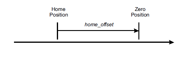
prspos
| Short description | Home offset |
|---|---|
| Dimension | Long |
| Default value | Retentive |
| Access type | Read - Write |
| Unit measure | um |
| Valid range | - |
| Parameter ID | 05 |
| Write conditions | - |
Description:
represents the difference between the zero position of the application and the home position sought during the homing procedure. When the homing procedure ends the zero position is shifted relative to the home position by adding a value of the parameter prspos . During the homing search the position of the axis distance between the home position and the position where loading takes place homing offset
deltaprspos
| Short description | Difference between the home positions |
|---|---|
| Dimension | Long |
| Default value | 0 |
| Access type | Read |
| Unit measure | Um/10 |
| Valid range | 0 to 999999 |
| Parameter ID | 06 |
| Write conditions | - |
Description:
E 'the difference between the home position before and the home position after homing. This value can be used to verify the correct operation of the transducer.
maxvel
| Short description | Maximum speed |
|---|---|
| Dimension | Long |
| Default value | Retentive |
| Access type | Read - Write |
| Unit measure | Uv |
| Valid range | 0 to 999999 |
| Parameter ID | 07 |
| Write conditions | st_still = 1, st_grouped = 0 |
Description:
is the setting of the speed limit. For a correct operation of the PID it must coincide with the speed that the axis reaches when the output value of implementation is maximum.
prsvel
| Short description | Speed for home switch search . |
|---|---|
| Dimension | Long |
| Default value | Retentive |
| Access type | Read - Write |
| Unit measure | Uv |
| Valid range | 0 to maxvel |
| Parameter ID | 08 |
| Write conditions | - |
Description:
is the speed of the axis used during the homing procedure for the search of the home switch.
sprsvel
| Short description | speed used to search for index (zero) pulse. |
|---|---|
| Dimension | Long |
| Default value | Retentive |
| Access type | Read - Write |
| Unit measure | Uv |
| Valid range | 0 to maxvel |
| Parameter ID | 09 |
| Write conditions | - |
Description:
is the speed used during the homing procedure for the search for index (zero) pulse.
toll
| Short description | Tolerance. |
|---|---|
| Dimension | Long |
| Default value | Retentive |
| Access type | Read - Write |
| Unit measure | Um/10 |
| Valid range | -999999 to 999999 |
| Parameter ID | 10 |
| Write conditions | - |
Description:
Defines a window, expressed in tenths of a unit of measurement, symmetrical around the positioning height ( setpos ).If the actual position ( posit ) is located within this window, you enter a state of tolerance axis ( st_toll ). The activation of st_toll does not occur as soon as the axis enters in this window, but after the delay time defined by parameter toldly and only if the condition of the actual position within the window remains during this time.

follerrthresh
| Short description | alarm threshold tracking error. |
|---|---|
| Dimension | Long |
| Default value | Retentive |
| Access type | Read - Write |
| Unit measure | Um/10 |
| Valid range | 0 to 2147483648 |
| Parameter ID | 11 |
| Write conditions | st_intenbl = 0 |
Description:
Defines a window, expressed in tenths of a unit of measure, around the virtual position ( posvirt ). If the actual position ( posit ) is outside of this window is activated the status of tracking error ( st_foller ) for a minimum of 300ms can not be set. If the actual position is inside, st_foller off (after the minimum time). This threshold is controlled only if the conditions are valid : st_error = 0, st_regoff = 0, st_calon = 0 and st_loopon = 1.

funint
| Short description | Operation entering the interrupt. |
|---|---|
| Dimension | Byte |
| Default value | Retentive |
| Access type | Read - Write |
| Unit measure | - |
| Valid range | 0 to 2 |
| Parameter ID | 12 |
| Write conditions | - |
Description:
Select the input operation in interrupt. The values have the following meanings:
0 = used for homing.
1 = capture the count and stores it in the delta .
2 = capture the count, reverses the sign, and stores it in the delta .
To use the operation modes 1 and 2 must be set st_intenbl = 1 through the command INTENBL .
funout
| Short description | digital output operation. |
|---|---|
| Dimension | Byte |
| Default value | Retentive |
| Access type | Read - Write |
| Unit measure | - |
| Valid range | 0 to 4 |
| Parameter ID | 13 |
| Write conditions | - |
Description:
Selects the operation of the digital output.
0 = output is not used. (The condition is never updated by the device)
1 = output state is equal to st_toll .
2 = output state is equal to st_still .
3 = output state is equal to st_foller .
4 = output state is equal to st_vconst .
ramptype
| Short description | |
|---|---|
| Dimension | Byte |
| Default value | Retentive |
| Access type | Read - Write |
| Unit measure | - |
| Valid range | 0 to 1 |
| Parameter ID | 14 |
| Write conditions | st_still = 1 |
Description:
Select the ramp type.
0 = linear ramp.
1 = ramp to S.
tacc
| Short description | Acceleration time. |
|---|---|
| Dimension | Word |
| Default value | Retentive |
| Access type | Read - Write |
| Unit measure | hundredths of a second |
| Valid range | 0 to 32767 |
| Parameter ID | 15 |
| Write conditions | st_grouped = 0 |
Description:
is used to define the acceleration and the time it takes to go from the axis speed 0 (zero speed) at maximum speed ( maxvel ). E 'can change the time tacc if a motion is in progress, in which case the value will be accepted provided that the positioning can be concluded properly to the command position.
tdec
| Short description | Deceleration time. |
|---|---|
| Dimension | Word |
| Default value | Retentive |
| Access type | Read - Write |
| Unit measure | hundredths of a second |
| Valid range | 0 to 32767 |
| Parameter ID | 16 |
| Write conditions | st_grouped = 0 |
Description:
is used to define the deceleration and the time it takes to go from the axis maximum speed ( maxvel ) at speed 0 (zero speed). E 'can change the time tacc if a motion is in progress, in which case the value will be accepted provided that the positioning can be concluded properly to the command position.
tinv
| Short description | Delay for reversing the direction. |
|---|---|
| Dimension | Word |
| Default value | Retentive |
| Access type | Read - Write |
| Unit measure | hundredths of a second |
| Valid range | 0 to 32767 |
| Parameter ID | 17 |
| Write conditions | - |
Description:
E 'the minimum waiting time between the end of a positioning and starting the next if the two directions are opposite. A motion command ( START , MANBW , …) performed during this minimum time is tracked and the status st_still immediately goes to 0.
mxnegfoller
| Short description | Maximum negative tracking error. |
|---|---|
| Dimension | Long |
| Default value | 0 |
| Access type | Read - Write |
| Unit measure | Um/10 |
| Valid range | 0 to 2147483648 |
| Parameter ID | 18 |
| Write conditions | - |
Description:
is the maximum value of the tracking error detected negative expressed in tenths of units.
mxposfoller
| Short description | Maximum positive value tracking error. |
|---|---|
| Dimension | Long |
| Default value | 0 |
| Access type | Read - Write |
| Unit measure | Um/10 |
| Valid range | 0 to 2147483648 |
| Parameter ID | 19 |
| Write conditions | - |
Description:
is the maximum value of the tracking error detected positive expressed in tenths of units.
toldly
| Short description | signal delay tolerance. |
|---|---|
| Dimension | Word |
| Default value | Retentive |
| Access type | Read - Write |
| Unit measure | hundredths of a second |
| Valid range | 0 to 32767 |
| Parameter ID | 20 |
| Write conditions | - |
Description:
Defines the time between the arrival of the axis in the tolerance band and the corresponding status message ( st_toll ).
pgain
| Short description | proportional gain. |
|---|---|
| Dimension | Word |
| Default value | Retentive |
| Access type | Read - Write |
| Unit measure | - |
| Valid range | 0 to 32767 |
| Parameter ID | 21 |
| Write conditions | - |
Description:
is the value of the proportional gain in the PID controller. Is entered in milliseconds (thus entering 1000, the coefficient will be equal to 1).
feedfw
| Short description | coefficient of feed forward. |
|---|---|
| Dimension | Word |
| Default value | Retentive |
| Access type | Read - Write |
| Unit measure | ‰ |
| Valid range | 0 to 2000 |
| Parameter ID | 22 |
| Write conditions | - |
Description:
is the coefficient percentage which, multiplied by the theoretical speed, generates the feed forward part of the control output. The value is entered in tenths (thus entering the 1000 share will be 100.0%)
integt
| Short description | Integration time of the 'tracking error. |
|---|---|
| Dimension | Word |
| Default value | Retentive |
| Access type | Read - Write |
| Unit measure | milliseconds |
| Valid range | 0 to 32767 |
| Parameter ID | 23 |
| Write conditions | - |
Description:
is the integration time of the error for the integral action of the PID controller.
derivt
| Short description | Derivation time lag error. |
|---|---|
| Dimension | Word |
| Default value | Retentive |
| Access type | Read - Write |
| Unit measure | milliseconds |
| Valid range | 0 to 32767 |
| Parameter ID | 24 |
| Write conditions | - |
Description:
is the derivation time of the PID controller of the derivative.
prsmode
| Short description | home position search mode |
|---|---|
| Dimension | Byte |
| Default value | Retentive |
| Access type | Read - Write |
| Unit measure | - |
| Valid range | 0 to 2 |
| Parameter ID | 25 |
| Write conditions | st_prson = 0 |
Description:
Select the mode of operation of the positioning of home
0 = homing with home switch input loading.
1 = Homing with input loading index (pulse).
2 = loading position homing home switch input without performing movements.
prsdir
| Short description | Direction of movement for the initial homing. |
|---|---|
| Dimension | Byte |
| Default value | Retentive |
| Access type | Read - Write |
| Unit measure | - |
| Valid range | 0 to 1 |
| Parameter ID | 26 |
| Write conditions | st_prson = 0 |
Description:
Select the initial direction of motion in procesura homing.
0 = forward.
1 = reverse.
prsswlogic
| Short description | |
|---|---|
| Dimension | Byte |
| Default value | Retentive |
| Access type | Read - Write |
| Unit measure | - |
| Valid range | 0 to 1 |
| Parameter ID | 27 |
| Write conditions | st_prson = 0 |
Description:
Select the logic of the state of the home switch.
0 = input switch home normally zero (off).
1 = input switch home normally one (active).
unitvel
| Short description | Unit of time for the speed calculation. |
|---|---|
| Dimension | Byte |
| Default value | Retentive |
| Access type | Read - Write |
| Unit measure | - |
| Valid range | 0 to 1 |
| Parameter ID | 28 |
| Write conditions | st_still = 1, st_grouped = 0 |
Description:
Select the unit of time for the parameters of speed.
0 = Um / min.
1 = Um / sec.
decpt
| Short description | Conversion factor for the unit of measurement of speed. |
|---|---|
| Dimension | Byte |
| Default value | Retentive |
| Access type | Read - Write |
| Unit measure | - |
| Valid range | 0 to 3 |
| Parameter ID | 29 |
| Write conditions | st_still = 1, st_grouped = 0 |
Description:
E 'the exponent of the scale factor of the unit of measurement for the speed of the position calculated as 10 <sup> decpt </ sup>. For example, if the unit of measurement of the position is millimeters, and unitvel = 1, the unit of measurement of the speed will be:
-
Mm / s (with decpt = 0),
-
Cm / s (with decpt = 1),
-
Dm / s (with decpt = 2),
-
M / s (with decpt = 3).
Therefore, both the speed that the settings of veloocità ( setvel , prsvel , …) will be expressed with this unit.
offset
| Short description | Offset analog output. |
|---|---|
| Dimension | Word |
| Default value | Retentive |
| Access type | Read - Write |
| Unit measure | bits |
| Valid range | -32768 to 32767 |
| Parameter ID | 30 |
| Write conditions | - |
Description:
Defines the bit values of the correction relating to the analog output to compensate for any offset of the analog input stage of the drive.
If the analog output is ± 10 volts then the value 32767 corresponds to +10 V and-10V to -32768.
setpos
| Short description | Position controlled. |
|---|---|
| Dimension | Long |
| Default value | 0 |
| Access type | Read - Write |
| Unit measure | um |
| Valid range | MINPOS to maxpos |
| Parameter ID | 31 |
| Write conditions | See Description |
Description:
E 'commanded position and expressed in units of measurement (um). E 'can change the commanded position even if a movement is in progress, in which case the axis will move to the new commanded position provided that this can be done without having to reverse the direction of movement. For example, if during a forward movement, is controlled to a lower position than the current axis of the new value setpos is not accepted and will trigger the warning status ( st_warning ).
setvel
| Short description | Speed controlled. |
|---|---|
| Dimension | Long |
| Default value | Retentive |
| Access type | Read - Write |
| Unit measure | Uv |
| Valid range | 0 to maxvel |
| Parameter ID | 32 |
| Write conditions | See Description |
Description:
is the speed with which placements are controlled by the START , MANBW and MANFW .
And 'possible to change the commanded speed even if a movement is under way to condition the trajectory generator is not in the deceleration phase.
vout
| Short description | output voltage. |
|---|---|
| Dimension | Byte |
| Default value | 0 |
| Access type | Read - Write |
| Unit measure | tenths of Volts |
| Valid range | -100 to 100 |
| Parameter ID | 33 |
| Write conditions | st_error = 0, st_cal = 1, st_grouped = 0, st_emrg = 0 |
Description:
During the calibration procedure ( st_cal = 1 ) is the value of the analog output voltage can be set. If st_cal = 0 the parameter is read-only and indicates the voltage on the analog output generated PID controller.
vel
| Short description | Current speed |
|---|---|
| Dimension | Long |
| Default value | 0 |
| Access type | Read |
| Unit measure | Uv |
| Valid range | - |
| Parameter ID | 34 |
| Write conditions | - |
Description:
is the value of the actual velocity of the axis expressed as a unit of measurement of speed. The update is performed every 250 ms. The unit of measurement depends on the parameters unitvel and decpt .
frq
| Short description | frequency of the input signals. |
|---|---|
| Dimension | Long |
| Default value | 0 |
| Access type | Read |
| Unit measure | Hz |
| Valid range | - |
| Parameter ID | 35 |
| Write conditions | - |
Description:
is the frequency value of the input signals to the bidirectional counter. The update is executed every 250 ms.
posit
| Short description | actual position. |
|---|---|
| Dimension | Long |
| Default value | Retentive |
| Access type | Read - Write |
| Unit measure | um |
| Valid range | - |
| Parameter ID | 36 |
| Write conditions | See Description |
Description:
is the value of the current axis position.
posit = encoder · measure / pulse
E 'can change this parameter even if a movement is in progress, provided that the new current location allows to conclude the positioning without having to reverse the direction of movement.
encoder
| Short description | Current position in encoder pulses. |
|---|---|
| Dimension | Long |
| Default value | Retentive |
| Access type | Read - Write |
| Unit measure | - |
| Valid range | - |
| Parameter ID | 37 |
| Write conditions | See Description |
Description:
The value of the current position of the encoder pulses.
E 'can change this parameter even if a movement is in progress, provided that the new current location allows to conclude the positioning without having to reverse the direction of movement.
follerr
| Short description | Following error. |
|---|---|
| Dimension | Long |
| Default value | 0 |
| Access type | Read |
| Unit measure | Um/10 |
| Valid range | - |
| Parameter ID | 38 |
| Write conditions | - |
Description:
is the instantaneous value of the following error expressed in tenths of units.
outreg
| Short description | Value of 'PID output + FF. |
|---|---|
| Dimension | Long |
| Default value | 0 |
| Access type | Read |
| Unit measure | bits |
| Valid range | -32768 to 32767 |
| Parameter ID | 39 |
| Write conditions | - |
Description:
the instantaneous value is expressed in bits of the output of the PID controller.
 | If the output of implementation is an analog output value corresponds to 32767 -32768 corresponds to 10V and-10V. |
|---|
ffwdreg
| Short description | Value of feed forward. |
|---|---|
| Dimension | Long |
| Default value | 0 |
| Access type | Read |
| Unit measure | bits |
| Valid range | -32768 to 32767 |
| Parameter ID | 40 |
| Write conditions | - |
Description:
the instantaneous value is expressed in bits of the feed forward.
propreg
| Short description | output value proportional. |
|---|---|
| Dimension | Long |
| Default value | 0 |
| Access type | Read |
| Unit measure | bits |
| Valid range | -32768 to 32767 |
| Parameter ID | 41 |
| Write conditions | - |
Description:
is proportional to the instantaneous value of the output in the PID controller.
intreg
| Short description | Value of output drive. |
|---|---|
| Dimension | Long |
| Default value | 0 |
| Access type | Read |
| Unit measure | bits |
| Valid range | -32768 to 32767 |
| Parameter ID | 42 |
| Write conditions | - |
Description:
is the instantaneous value of the output in the integral PID controller.
derreg
| Short description | Value of 'output derivative. |
|---|---|
| Dimension | Long |
| Default value | 0 |
| Access type | Read |
| Unit measure | bits |
| Valid range | -32768 to 32767 |
| Parameter ID | 43 |
| Write conditions | - |
Description:
is the instantaneous value of the derivative in the PID controller output.
delta
| Short description | sum value for the command DELCNT. |
|---|---|
| Dimension | Long |
| Default value | 0 |
| Access type | Read - Write |
| Unit measure | um |
| Valid range | -999999 to 999999 |
| Parameter ID | 44 |
| Write conditions | st_intenbl = 0 |
Description:
This is the value that is used by the DELCNT to be added to the current position. Moreover, this parameter is also used to store the current position when the capture occurs from input interrupt.
posvirt
| Short description | virtual position. |
|---|---|
| Dimension | Long |
| Default value | 0 |
| Access type | Read |
| Unit measure | um |
| Valid range | - |
| Parameter ID | 45 |
| Write conditions | - |
Description:
The value of the instantaneous position commanded.
brakepos
| Short description | Starting position for braking. |
|---|---|
| Dimension | Long |
| Default value | 0 |
| Access type | Read |
| Unit measure | um |
| Valid range | - |
| Parameter ID | 46 |
| Write conditions | - |
Description:
is the value of the position in which will start the deceleration ramp.
wrncode
| Short description | Identification code warning |
|---|---|
| Dimension | Byte |
| Default value | 0 |
| Access type | Read |
| Unit measure | - |
| Valid range | |
| Parameter ID | 47 |
| Write conditions | - |
Description:
Indicates the type of warning detected by the device. For more information, refer to the chapter.
wrnpar
| Short description | id parameter that caused the warning. |
|---|---|
| Dimension | Byte |
| Default value | 0 |
| Access type | Read |
| Unit measure | - |
| Valid range | |
| Parameter ID | 48 |
| Write conditions | - |
Description:
Indicates which parameter caused the warning detected by the device. For more information, refer to the chapter.
wrnvalue
| Short description | Code identifying the cause of the warning |
|---|---|
| Dimension | Byte |
| Default value | 0 |
| Access type | Read |
| Unit measure | - |
| Valid range | - |
| Parameter ID | 49 |
| Write conditions | - |
Description:
Indicates the cause of the warning detected by the device. For more information, refer to the chapter.
errcode
| Short description | Identification code of the error. |
|---|---|
| Dimension | Byte |
| Default value | 0 |
| Access type | Read |
| Unit measure | - |
| Valid range | - |
| Parameter ID | 50 |
| Write conditions | - |
Description:
Indicates the type of error detected by the device. For more information, refer to the chapter.
errpar
| Short description | id parameter that caused the error. |
|---|---|
| Dimension | Byte |
| Default value | 0 |
| Access type | Read |
| Unit measure | - |
| Valid range | - |
| Parameter ID | 51 |
| Write conditions | - |
Description:
Indicates the parameter that caused the error detected by the device. For more information, refer to the chapter.
errvalue
| Short description | Code identifying the cause of the error |
|---|---|
| Dimension | Byte |
| Default value | 0 |
| Access type | Read |
| Unit measure | - |
| Valid range | - |
| Parameter ID | 52 |
| Write conditions | - |
Description:
Indicates the type of cause of the error detected by the device. For more information, refer to the chapter.
5. States list
st_capture
| Short description | Status counting captured. |
|---|---|
| Default value | 0 |
| Status ID | 53 |
Description
Indicates that the capture count has occurred.
0 = capture count void.
1 = capture count occurred.
st_emrg
| Short description | state of emergency. |
|---|---|
| Default value | 0 |
| Status ID | 54 |
Description
Indicates the state of emergency axis.
0 = axis is not in an emergency.
1 = axis in an emergency.
st_toll
| Short description | Status of tolerance. |
|---|---|
| Default value | 0 |
| Status ID | 55 |
Description
Indicates the status of axis tolerance.
0 = axis is not within tolerance.
1 = axis tolerance.
st_prsok
| Short description | Result of homing sequence. |
|---|---|
| Default value | 0 |
| Status ID | 56 |
Description
Indicates whether the homing sequence was successful
0 = homing procedure is not carried out or not completed correctly.
1 = Homing carried out and completed successfully.
The state is deactivated with the command RSPRSOK .
st_still
| Short description | Status of movement. |
|---|---|
| Default value | 1 |
| Status ID | 57 |
Description
Indicates the status of the axis.
0 = moving axis.
1 = axis is stationary.
st_prson
| Short description | Status of the homing procedure. |
|---|---|
| Default value | 0 |
| Status ID | 58 |
Description
Indicates whether homing procedure is running.
0 = Homing is not running.
1 = Homing running.
st_movdir
| Short description | Direction of movement. |
|---|---|
| Default value | 0 |
| Status ID | 59 |
Description
Indicates the direction of movement.
0 = forward.
1 = reverse.
When the axis has stopped the status indicates the direction of the last movement you make.
st_loopon
| Short description | Activation of the position loop. |
|---|---|
| Default value | 0 |
| Status ID | 60 |
Description
It indicates the position loop.
0 = position loop off.
1 = position loop active.
st_foller
| Short description | Error status tracking. |
|---|---|
| Default value | 0 |
| Status ID | 61 |
Description
Indicates that the value of following error ( follerr ) exceeded the alarm threshold ( follerrthresh ). When you activate this remains for a minimum period of 300 ms.
0 = tracking error below the alarm threshold.
1 = tracking error exceeds the threshold alarm.
st_regoff
| Short description | Disable output of the positioner and implementation. |
|---|---|
| Default value | 0 |
| Status ID | 62 |
Description
Indicates whether the device allows placements and updates the output implementation.
0 = placements enabled.
1 = placements disabled.
st_cal
| Short description | Calibration status. |
|---|---|
| Default value | 0 |
| Status ID | 63 |
Description
Indicates that the calibration status is active.
0 = not active calibration status.
1 = active calibration status.
st_acc
| Short description | State of acceleration. |
|---|---|
| Default value | 0 |
| Status ID | 64 |
Description
Indicates that the trjectory generator is in the acceleration phase.
0 = not during acceleration.
1 = acceleration phase.
st_dec
| Short description | State of deceleration. |
|---|---|
| Default value | 0 |
| Status ID | 65 |
Description
Indicates that the trjectory generator is in the deceleration phase.
0 = not decelerating.
1 = deceleration phase.
st_vconst
| Short description | Status of constant speed. |
|---|---|
| Default value | 0 |
| Status ID | 66 |
Description
Indicates that the trjectory generator is in the phase of constant velocity.
0 = not at a constant speed.
1 = constant velocity phase.
st_warning
| Short description | Presence of a warning. |
|---|---|
| Default value | 0 |
| Status ID | 67 |
Description
Indicates the status of the warning device to recognize the type of warning you should refer to the variables wrncode , wrnvalue and wrnpar .
0 = not present warning.
1 = this warning.
—
st_error
| Short description | Presence of an error. |
|---|---|
| Default value | 0 |
| Status ID | 68 |
Description
Indicates the error status of the device, to recognize the type of error should refer to the variables errcode and errvalue .
0 = no error present.
1 = error present.
st_intenbl
| Short description | Counter capture by interrupt enabled. |
|---|---|
| Default value | 0 |
| Status ID | 69 |
Description
Indicates whether the capture of the count by input interrupt is enabled.
0 = Interrupt not enabled by capturing count.
1 = interrupt enabled by capturing count.
st_cntlock
| Short description | Indicates whether or not the count is updated by reading the encoder pulses. |
|---|---|
| Default value | Retentive |
| Status ID | 70 |
Description
Indicates the enable status of the update of the count.
0 = the count is updated.
1 = the count is not updated and remains frozen at the last value acquired.
st_cntrev
| Short description | State of the counterclockwise direction for the increase in the count. |
|---|---|
| Default value | Retentive |
| Status ID | 71 |
Description
Indicates the direction of rotation that causes the increase of the count.
0 = clockwise.
1 = counterclockwise.
st_grouped
| Short description | Indicates whether the device belongs to a device or not. |
|---|---|
| Default value | 0 |
| Status ID | 72 |
Description
During some operations such as interpolation ANPOS2 a device can belong to a device group. If the st_grouped = 1 you can not edit the count values will use positioning commands.
0 = Device does not belong to a group.
1 = Device in a group.
6. Commands list
INTENBL
| Short description | Enable the capture of the count. |
|---|---|
| Condition | st_error = 0, funint> 0 |
| Default value | |
| Command ID | 73 |
Description
Enable the capture of the count
INTDSBL
| Short description | Disable the capture of the count. |
|---|---|
| Condition | st_error = 0, funint> 0 |
| Default value | 0 |
| Command ID | 73 |
Description
Disable the capture of the count
EMRG
| Short description | Emergency. |
|---|---|
| Condition | st_error = 0 |
| Default value | |
| Command ID | 74 |
Description
Puts the axis in emergency stopping, without deceleration ramp, the possible positioning and puts st_emrg 1. Also inhibits the execution of all the movement controls and disables the position loop.
RESUME
| Short description | Recovering from an emergency condition. |
|---|---|
| Condition | st_error = 0, st_emrg = 1 |
| Default value | |
| Command ID | 74 |
Description
Reset the emergency condition of the axis, are rehabilitated the position loop and positioning commands.
STOP
| Short description | Stops the current positioning. |
|---|---|
| Condition | st_error = 0, st_regoff = 0, st_emrg = 0, st_still = 0, st_cal = 0, st_grouped = 0 |
| Default value | |
| Command ID | 75 |
Description
Kills the current positioning of the axis by backing the arrest with the programmed deceleration ramp.
START
| Short description | Start of placement. |
|---|---|
| Condition | st_error = 0, st_regoff = 0, st_emrg = 0, st_still = 1, st_cal = 0, st_grouped = 0 |
| Default value | |
| Command ID | 76 |
Description
Controls the positioning at the level setpos speed setvel .
PRESET
| Short description | Start search the home position. |
|---|---|
| Condition | st_error = 0, st_regoff = 0, st_emrg = 0, st_still = 1, st_cal = 0, prsvel> 0, sprevel> 0 |
| Default value | |
| Command ID | 77 |
Description
Starts the search of the home position, active state st_prson turns off state st_prsok . If the search is already active, the command performs the inversion of the direction of movement.
LOOPON
| Short description | Enable the position loop. |
|---|---|
| Condition | st_error = 0, st_grouped = 0 |
| Default value | |
| Command ID | 78 |
Description
Enable the position loop by activating the PID controller and puts st_loopon .
LOOPOFF
| Short description | Disable the position loop. |
|---|---|
| Condition | st_error = 0, st_grouped = 0 |
| Default value | |
| Command ID | 78 |
Description
Disables the disabling the PID position loop and sets st_loopon 0; E 'can still perform movements but the output of the implementation is calculated by the value of virtual speed and K OpenLoop (see description block CLOSED LOOP POSITION CONTROL).
MANFW
| Short description | command JOG forward. |
|---|---|
| Condition | st_error = 0, st_regoff = 0, st_emrg = 0, st_still = 1, st_cal = 0, st_prson = 0, st_grouped = 0 |
| Default value | |
| Command ID | 79 |
Description
Command positioning maxpos with the speed setvel . If the current position is greater than or equal to maxpos , the command has no effect.
MANBW
| Short description | JOG command back. |
|---|---|
| Condition | st_error = 0, st_regoff = 0, st_emrg = 0, st_still = 1, st_cal = 0, st_prson = 0, st_grouped = 0 |
| Default value | |
| Command ID | 80 |
Description
Command positioning MINPOS with the speed setvel . If the current position is less than or equal to MINPOS , the command has no effect.
CALON
| Short description | Enable calibration status. |
|---|---|
| Condition | st_error = 0, st_grouped = 0 |
| Default value | |
| Command ID | 81 |
Description
Enable the calibration status of implementation in which the output is no longer updated by the PID controller but you can set the value using the vout .
CALOFF
| Short description | Disable calibration status. |
|---|---|
| Condition | st_error = 0, st_grouped = 0 |
| Default value | |
| Command ID | 81 |
Description
Exit the calibration state of the output so that the implementation goes back to being controlled by the PID controller.
RSCAPTURE
| Short description | Reset status st_capture. |
|---|---|
| Condition | st_error = 0 |
| Default value | |
| Command ID | 82 |
Description
Clears the capture status of the count st_capture .
CNTLOCK
| Short description | Disable the update count. |
|---|---|
| Condition | st_error = 0, st_grouped = 0 |
| Default value | |
| Command ID | 83 |
Description
Disable the update of the count.
CNTUNLOCK
| Short description | Enable the update count. |
|---|---|
| Condition | st_error = 0, st_grouped = 0 |
| Default value | |
| Command ID | 83 |
Description
Enable the update count if it is locked ( st_cntlock = 1).
CNTREV
| Short description | Direction increase counting counterclockwise. |
|---|---|
| Condition | st_error = 0, st_grouped = 0 |
| Default value | |
| Command ID | 84 |
Description
Sets the direction of increase of the count to CCW.
CNTDIR
| Short description | Direction increase in counting time. |
|---|---|
| Condition | st_error = 0, st_grouped = 0 |
| Default value | |
| Command ID | 84 |
Description
Sets the direction of increase of the count-time.
REGOFF
| Short description | Disable positioner output and implementation. |
|---|---|
| Condition | st_still = 1, st_error = 0, st_grouped = 0 |
| Default value | |
| Command ID | 85 |
Description
Disable the positioner and the output of implementation.
REGON
| Short description | Enable output of the positioner and implementation. |
|---|---|
| Condition | st_regoff = 1, st_error = 0, st_grouped = 0 |
| Default value | |
| Command ID | 85 |
Description
Enable the positioner and the output of implementation.
DELCNT
| Short description | Command to modify posit the value of delta . |
|---|---|
| Condition | st_psron = 0, = 0 st_cal, st_error = 0, st_grouped = 0, see description |
| Default value | |
| Command ID | 86 |
Description
Total current position ( posit ) the value specified by the delta . E 'can run this command even if a movement is under way on condition that the new current position for concluding the placement without having to reverse the direction of movement.
RSPRSOK
| Short description | Reset state homing OK. |
|---|---|
| Condition | - |
| Default value | |
| Command ID | 87 |
Description
Reset state st_prsok .
RSERR
| Short description | Reset error state. |
|---|---|
| Condition | - |
| Default value | |
| Command ID | 88 |
Description
Clears the error status ( st_error ) in the case is no longer on the error condition.
RSWRN
| Short description | Reset state warning. |
|---|---|
| Condition | - |
| Default value | |
| Command ID | 89 |
Description
Reset state st_warning .
7. Errori e Warnings
7.1 Errors
When the device is not able to perform the operations resulting from an incorrect user programming signals this condition through the activation status st_error . The device also makes available, through the values of the parameters errcode , errvalue and errpar some information to better understand the type of error condition and which generated it. Such information and error status st_error , there remain until you run the appropriate command RSERR that deletes them.
The following table specifies the values of errcode :
| errcode | Description |
|---|---|
| 0 | No mistake. |
| 1 | Data error: There are values out of range in the parameters. |
| 2 | Configuration error. |
Use the parameters errvalue and errpar you can get more detailed information about the error.
The errpar always indicates the ID of the parameter that caused the error.
Instead currently the errvalue is not used and is always 0.
7.2 Warnings
When a parameter setting of the device is not accepted or a command cannot be executed, the device signals this condition by activating the st_warning status.
The device also makes available, through the values of the parameters wrncode , wrnvalue and wrnpar information to better understand the type of warning and what condition generated it.
Such information and the status of warning st_warning , there remain until you run the appropriate command RSWRN that deletes them.
The following table specifies the values of wrncode :
| wrncode | Description |
|---|---|
| 0 | No warning. |
| 1 | Setting data out of range. |
| 2 | Change parameter is not accepted. |
| 3 | Command not accepted: the execution conditions are not met. |
Use the wrnvalue and wrnpar parameters to get more details about the warning.
The wrnpar always indicates the ID of the parameter that caused the warning.
The wrnvalue is currently not used and is always 0.