Tabela de conteúdos
MODBUS SLAVE
| Name | ModbusSlave |
|---|---|
| Version | 1 |
| Major release | 0 |
| Minor release | 3 |
| Title | Unit for implement a Modbus® slave (or server) communication with extended addressing. |
1. DESCRIPTION
The unit implement a complete data exchange of a Modbus slave (or server) communication line. The main features are:
-
Usable with serial communication line (slave) or with TCP/IP protocol (server).
-
Management of an extended address space (extended than the internal Modbus device space). Addressing of max 256 Inputs registers and 256 Holding registers.
-
Writing detect on the holding registers with the differentiation if the value is same or different.
-
Internal state machine to clearly identify the operating status of the unit.
-
Message counters (processed successfully and error message).
-
Possibility of closing the communication channel to free the communication port.
2. STATE MACHINE
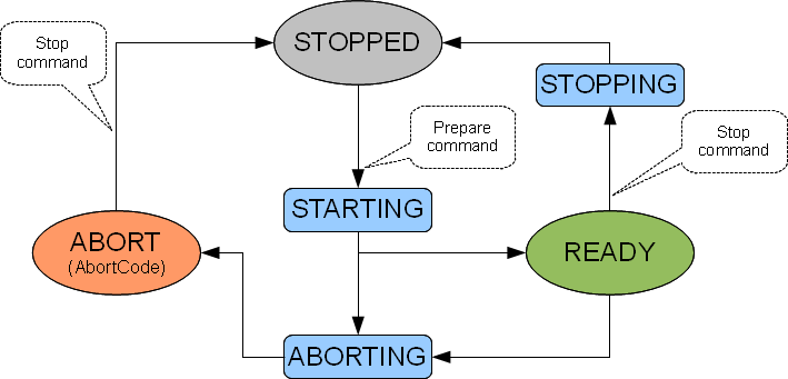
The large circles represent stable states. They are:
STOPPED: state where the unit does not perform any activity. It is also the initial state.
READY: state of full activity
ABORT: there is a serious error, the unit switches to the safe state and waits for a stop command. AbortCode provides an identification code of the reason that set that state.
The rectangles indicate transient states:
STARTING: state in which the unit checks all the settings data and if the values are within the limits opens the communication channel.
STOPPING: nothing do in this implementation.
ABORTING: nothing do in this implementation.
Baloons are commands that can be sent to change the state:
Prepare, commands the unit to switch into ready state. Prior to this command must be configured all the communication parameters.
Stop, commands the unit to switch into STOPPED state. The communication channel is closed if it was open.
3. OPERATION
The unit operation is represented by the following blocks:
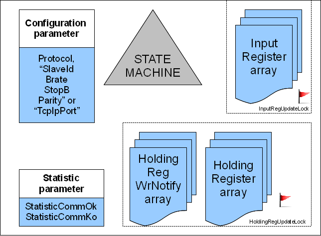
Configuration parameter are the parameters required to open the communication channel.
State machine is the state machine described in the previous chapter.
Statistic parameter values are useful to generate a statistic of operation.
Then there are three arrays, one to hold the values of InputRegisters, one for HoldingRegisters and one for detect if a HoldingRegister was written.
4. PUBLIC SYMBOLS
Below is a table with an explanation of the public symbols.
| Name | Type | Size | Access Type | Description |
| State | GLOBAL | B | OUT | Actual state. The values can be STOPPED (0), STARTING (1), READY (2), ABORTING (3), ABORTED (4), STOPPING (5) |
| Prepare | GLOBAL | F | IN | Command to set STARTING state. |
| Stop | GLOBAL | F | INOUT | Command to set STOPPING state. |
| AbortCode | GLOBAL | B | INOUT | Indicates a code that helps to understand the cause of the passage of state machine in ABORTED. Value could be: ABORT_NONE (0) no error, ABORT_SLAVEID (1) Wrong value of slave id, ABORT_PROTOCOL (2) Wrong value of protocol, ABORT_BRATE (3) wrong value brate, ABORT_STOPB (4) wrong value stopb, ABORT_PARITY (5) wrong parity value, ABORT_NOTOPEN (6) the MODBUS device was unable to open the communication port, ABORT_NOTCLOSE (7) The device failed to close MODBUS communication port |
| HoldingRegUpdateLock | GLOBAL | F | INOUT | This flag is set by the unit each time there is a write message, and then the HoldingRegisters array is updated. This flag MUST be set to zero by the QCL after using the new data received. If this flag is not clear the unit is no longer able to decode modbus messages. |
| InputRegUpdateLock | GLOBAL | F | INOUT | This flag must be used only if you want to archive atomicity in InputRegister data update. In this case, you must set this flag before updating the data Inputegister and put it back to zero at the end. If you not need atomicity leave this zero. |
| ErrorCode | GLOBAL | B | INOUT | Indicates an error code protocol. Value could be: ERR_NONE (0), ERR_UNSUPP_TYPE (1) error: unsupported type messages, ERR_START_ADDR (2) error: start address is out of address space, ERR_END_ADDR (3) error: end address is out of address space, ERR_INVALID_ADDR (4) error: invalid address, ERR_INVALID_NUM (5) error: invalid register number. This code indicates the last error code occurred. It must be reset from the QCL. |
| Protocol | GLOBAL | B | INOUT | Modbus protocol selection (ASCII (0), RTU (1) or TCPIP (2)) |
| SlaveId | GLOBAL | B | INOUT | Modbus slave id (1 ÷ 127). Used only with Protocol = ASCII or RTU. |
| Brate | GLOBAL | L | INOUT | Serial brate. (4800, 9600, 19200, 38400, 57600, 115200).Used only with Protocol = ASCII or RTU. |
| StopB | GLOBAL | B | INOUT | Stop bits (0,1,2). Used only with Protocol = ASCII or RTU. |
| Parity | GLOBAL | B | INOUT | PARITY_NONE (0), PARITY_ODD (1), PARITY_EVEN (2). Used only with Protocol = ASCII or RTU. |
| ReplyDelay | GLOBAL | W | INOUT | slave reply delay (ms). If the master does not require delays this parameter be left at zero. |
| TcpIpPort | GLOBAL | W | INOUT | TCPIP communication port. Used only with Protocol = TCPIP, defines the communication port for messages. If this parameter is left to zero, the unit uses the default value of the Modbus protocol (502). |
| StatisticCommOk | GLOBAL | L | INOUT | Indicate the total amounth of right message |
| StatisticCommKo | GLOBAL | L | INOUT | Indicate the total amounth of error message |
| InputRegisters | ARRGBL | W | INOUT | Array of 256 items for InputRegisters value |
| HoldingRegisters | ARRGBL | W | INOUT | Array of 256 items for HoldingRegisters value |
| HoldingRegWrNotify | ARRGBL | B | INOUT | Array of 256 elements for notify write into registers. Value 1 is for write access with the same value, 2 is for a new value |
5. COMMUNICATION WITH TCPIP PROTOCOL
If Qmove product is equipped with a network adapter, you could use the MODBUS device and then this QCL Feature with a TCPIP communication channel. This Modbus TCP/IP communication acts as a TCPIP server listening on TcpIpPort port. Modbus communication could coexist with PROG AND USER port over ethernet (in other words you can simultaneously have Modbus TCP/IP, debug your application with QView and a Qem HMI, all over ethernet) . To enable communication via TCPIP is necessary to:
-
Enter n°43 as a communication channel in MODBUS device declaration.
-
The Protocol parameter must be set to the value TCPIP (2).
-
You must program TcpIpPort only if necesary instead of slaveId, Brate, StopB, Parity.
IP address is the same of network adapter. Check you product documentation for how to chaneg it. In general you can change Qmove product IP address in many ways:
-
Using QConfigurator-1 utility (via PROG serial cable)
-
Using QConfigurator-2 utility (via ethernet cable)
-
Using system function if qmove product has a display
6. EXAMPLES OF USE
6.1 SERIAL COMMUNICATION
These are the steps to get a simple working example of a serial communication:
-
Create a new project with QView-6
-
Add a unit type configuration. Edit BUS section according with your product name. In the section INTDEVICE insert the declaration of a device MOSBUS:
INTDEVICE
...
UserPort  MODBUS 0008  1
Pay attention to the last field number of the declaration (1) that is used to select the communication port. Usually it is zero for PROG port, one for USER port, two for aux1, tree for aux2 port. Check hardware manual for assurance.
-
In the REFERENCES section (always in the unit configuration) add the following code:
REFERENCES
MDBSLAV1.modbus = UserPort
-
Add a unit QCL with a name (for example, INIT).
-
Add to the project the QCL Feature unit ModbusSalve10 and name MDBSLAV1
-
Edit the INIT unit and add the following code:
CONST
    ; general
    TRUE                        1
    FALSE                       0

; main entry point
BEGIN
    CALL TASK_INIT
    WHILE TRUE
        CALL TASK_EXECUTE
        WAIT 1
    ENDWHILE
END

;===
;   Task initialization
;
SUB TASK_INIT
    WAIT MDBSLAV1.State EQ MDBSLAV1.STOPPED         ; wait for stopeed state
    MDBSLAV1.Protocol = MDBSLAV1.RTU
    MDBSLAV1.SlaveId = 5
    MDBSLAV1.Brate = 57600
    MDBSLAV1.StopB = 1
    MDBSLAV1.Parity = 0
    MDBSLAV1.Prepare = 1			    ; command prepare state
    WAIT MDBSLAV1.State EQ MDBSLAV1.READY           ; wait for ready state
ENDSUB


;===
;   Task execution
;
SUB TASK_EXECUTE
    IF MDBSLAV1.HoldingRegUpdateLock EQ TRUE
        IF MDBSLAV1.HoldingRegWrNotify[1] EQ 2
            ; place here your specific  code to elaborate Holding register nr 1 change
            NOP
            MDBSLAV1.HoldingRegWrNotify[1] = 0
        ENDIF
        MDBSLAV1.HoldingRegUpdateLock = FALSE
    ENDIF

    MDBSLAV1.InputRegisters[1] = MDBSLAV1.InputRegisters[1] + 1

ENDSUB
6.2 TCPIP COMMUNICATION
These are the steps to get a simple working example of a communication TCPIP:
-
Create a new project with QView-6
-
Add a unit type configuration. Edit BUS section according with your product name and firmware version. In the section INTDEVICE insert the declaration of a device MOSBUS:
INTDEVICE
...
UserPort  MODBUS 0008  43
Pay attention to the last field (43) that is used to select the correct socket communication. It is always 43.
-
In the REFERENCES section (always the unit configuration) add the following code:
REFERENCES
MDBSLAV1.modbus = UserPort
-
Add a unit QCL with a name (for example, INIT).
-
Add to the project the QCL Feature unit ModbusSalve10 and name MDBSLAV1
-
Edit the INIT unit and add the following code:
CONST
	; general
	TRUE						1
	FALSE						0

; main entry point
BEGIN
	CALL TASK_INIT
	WHILE TRUE
		CALL TASK_EXECUTE
		WAIT 1
	ENDWHILE
END

;===
;	Task initialization
;
SUB TASK_INIT
	WAIT MDBSLAV1.State EQ MDBSLAV1.STOPPED			; wait for stopeed state
	MDBSLAV1.Protocol = MDBSLAV1.TCPIP
	MDBSLAV1.SlaveId = 1
	MDBSLAV1.Prepare = 1					; command prepare state
	WAIT MDBSLAV1.State EQ MDBSLAV1.READY			; wait for ready state
ENDSUB


;===
;	Task execution
;
SUB TASK_EXECUTE
    IF MDBSLAV1.HoldingRegUpdateLock EQ TRUE
    	IF MDBSLAV1.HoldingRegWrNotify[1] EQ 2
	    ; place here your specific  code to elaborate Holding register nr 1 change
    	    NOP
    	    MDBSLAV1.HoldingRegWrNotify[1] = 0
        ENDIF
    	MDBSLAV1.HoldingRegUpdateLock = FALSE
    ENDIF

    MDBSLAV1.InputRegisters[1] = MDBSLAV1.InputRegisters[1] + 1
ENDSUB
7. LIMITATIONS
-
The unit currently handles only Modbus messages type 3 (holding register read), 4 (read input register), 6 (force register) , 16 (force multiple registers). It does not handle modbus messages 1 (read coil) , 5 (force coil), 15 (force multiple coils). In case of receiving a message not supported the ErrorCode ERR_UNSUPP_TYPE (1) is set. When ErrorCode is set for master (or client) side no protocol error is detected.
-
The maximum number of registers readable or writable with a single message is fixed at 32.
-
Not all qmove product supports baud rate of 115200 baudrate. Check product documentation.
8. NOTES
-
It is possible use this QCL Feature in applications where there are multiple Modbus slave channels (simultaneously active) . For example if you need two channels you have to define two device device MODBUS (each setting a different communication port). In the REFERENCES section there will be two lines to reference the device with two QCL Feature. The project must include two units QCL feature type ModbusSlave10. You need also two initialization unit (like INIT in the previus example).
-
The response time of the message depends on various factors. They are: the sampling time of the MODBUS device. The cycle time of the application QCL (Running Time into CPU panel). The time that the application uses to process messages received (that is the time that the flag HoldingRegUpdateLock and InputRegUpdateLock keep active).
-
Since Modbus data type is word (16 bit) if you have to excange 32 bit data value you need to encode / decode data into two registers. Follow is a code example for encode data into Inputregister value and decode HoldingRegister value to 32 bit variable:
...
...

GLOBAL
    posit                       L       ; 32 bit position example
    setpos                      L       ; 23 bit target position example

    wordDw                      W
    wordUp                      W
    long                        L

...
...

    ; check if anyone write in Holding register nr 3-4 and decode to setpos 32 bit variable
    IF (MDBSLAV1.HoldingRegWrNotify[3] EQ 2) OR (MDBSLAV1.HoldingRegWrNotify[4] EQ 2)
        wordDw = MDBSLAV1.HoldingRegisters[3]
        wordUp = MDBSLAV1.HoldingRegisters[4]
        VR10WrdtoLng (wordUp,wordDw, setpos)
    ENDIF

...
...

    ; encode 32 bit value into InputRegisters 5 & 6
    long = posit
    VR10LngtoWrd (long, wordUp, wordDw)
    MDBSLAV1.InputRegisters[5] = wordDw
    MDBSLAV1.InputRegisters[6] = wordUp

...
...
9. CHANGE LOG
| QCL feature release | Description | Note | Date |
|---|---|---|---|
| 1.0.1 | Initial release | 06/11/2013 | |
| 1.0.2 | Fix SlaveId setting in TCPIP server mode | 03/03/2014 | |
| 1.0.3 | Fix Parity parameter size, add new example projects | 22/09/2015 |
10. DOWNLOAD
Click here to download unit and examples.
Zip contents:
| File or folder name | Description |
|---|---|
| MDBSLAV1.UNT | Qcl feature file |
| MODBUS_SLAVE_SERIAL_EXAMPLE | Example for serial communication |
| MODBUS_SLAVE_TCPIP_EXAMPLE | Example for server TCPIP communication |