目录
~~BOZZA~~
CNTCMD004ACP - HDT drive cable


1. Information
| | |||
| Document: | 31200166 | ||
|---|---|---|---|
| Description: | Installation and Maintenance Manual | ||
| Drawn up: | Riccardo Furlato | ||
| Approved | Gabriele Bazzi | ||
| Link: | http://www.qem.eu/doku/doku.php/strumenti/accessori/cavi/31200166 | ||
| Language: | English | ||
| Release | Description | Notes | Date |
| 01 | New manual | 07/01/2014 |
2. Description:
I/O cable and connector for DGM-HDT drive.
2.1 Product identification
In base al Codice d'ordinazione dello strumento è possibile ricavarne esattamente le caratteristiche. Verificare che le Caratteristiche dello strumento corrispondano alle Vostre esigenze.
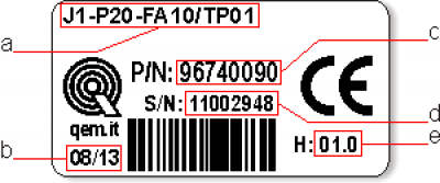
2.2 Product label

-
a - Codice di ordinazione
-
b - Settimana di produzione: indica la settimana e l'anno di produzione
-
c - Part number: codice univoco che identifica un codice d'ordinazione
-
d - Serial number: numero di serie dello strumento, unico per ogni pezzo prodotto
-
e - Release hardware: release dell' hardware
2.3 Ordering code
| Model | Caratteristiche | |||||||
| J1 | - | P20 | - | FA | - | 10 | / | TP01 |
|---|---|---|---|---|---|---|---|---|
| TP00 = Codice tastiera (TP00 = pannello con touch-screen resistivo, logo e tasti funzione personalizzabili); TP01 = pannello con touch-screen resistivo, logo e tasti funzione standard QEM |
||||||||
| 10 = Versione firmware (00 = non installato) | ||||||||
| F = Livello tecnologico A = Versione hardware | ||||||||
| P = Solo Tasti funzione 2 = display lcd grafico 5� TFT-256 COLORI-800x480px; dimensione pannello anteriore (168x144mm); tastiera 7 tasti + 11 led; contenitore a norme DIN 43700; 0 = Corrispondenza firmware-hardware | ||||||||
| J1 = Famiglia Qmove “HMI+PLC” |
3. Wiring diagram
| A - Input |  | CNT Connettore 44 vie maschio  Vista lato saldature |
| B - Output | ||
| Differential analog input | ||
| PF - Simulated encoder outputs of 5V line driver type |
| PIN NAME | CNT | COLOR | DESCRIPTION | |||
|---|---|---|---|---|---|---|
| Cavo 4×0.25 non schermato | ||||||
| ENA | 25 | WHITE | Ingresso Drive ENABLE | A | ||
| RUN | 12 | GREEN | Ingresso ENABLE REFERENCE | |||
| RESET | 41 | BROWN | RESET input | |||
| COMMON | 9-10 | YELLOW | Comune per ingressi e uscite digitali | |||
| Cavo 4×0.25 non schermato | ||||||
| DRV_OK | 13 | YELLOW | CONTATTO PULITO DRIVE OK (Contatti di un rele') |  | B | |
| DRV_OK | 28 | GREEN | ||||
| I2T | 44 | WHITE | FAULT | out +24V |
||
| +24 | 39 | BROWN | Ingresso +24V per alimentazione uscite digitali | |||
| Cavo 3×0.25 schermato | ||||||
| REF+ | 16 | BROWN | Ingresso differenziale non invertente riferimento principale di velocita' |  | ||
| REF- | 1 | GREEN | Ingresso differenziale invertente riferimento principale di velocita' | |||
| COMMON | 18 | WHITE | Common analog signals | |||
| SCREEN | CARCASSA | SCREEN | Calza del cavo dei segnali analogici | |||
| Cavo 8×0.25 schermato | ||||||
| Z+ | 21 | BROWN | CHZ+ | Out Z |  | PF |
| Z- | 6 | WHITE | CHZ- | |||
| B+ | 5 | RED | CHB+ | Out B | |
|
| B- | 34 | BLUE | CHB- | |||
| A+ | 35 | GREEN | CHA+ | Out A | |
|
| A- | 20 | YELLOW | CHA- | |||
| 0L | 36 | PINK | Common |
4. Wiring example
4.1 Collegamento tra HB548.05 e Drive serie DGM
Per poter collegare ad un HB548, un drive HDT, � necessario l'uso di un IQ007, per convertire i segnali LINE-DRIVER dell'encoder simulato in segnali PUSH-PULL.
| HB548 | DGM drive | Nome segnale | Notes | ||||
|---|---|---|---|---|---|---|---|
| 23 | ←———————- | 16 | REF+ | ||||
| 24 | ←———————- | 1 | REF- | ||||
| ←———————- | 18 | COMMON | |||||
| CARCASSA | SCREEN | ||||||
| 27 | ←———————- | 25 | ENA | ||||
| ←———————- | 12 | RUN | |||||
| 1 | ←———————————————– | 24 Vac | Dal un secondario dedicato di un trasformatore | ||||
| 2 | ←———————————————– | ||||||
| 3 | ←———————————————– | GROUND | |||||
| IQ007 | |||||||
| 13 | ← | 4 | 14 | ← | 35 | A+ | |
| 13 | ← | 20 | A- | ||||
| 14 | ← | 3 | 12 | ← | 5 | B+ | |
| 11 | ← | 34 | B- | ||||
| 12 | ← | 1 | 8 | ← | 36 | 0L | |
| 5 | ← | ||||||
| 16 | ← | ||||||
| 6,25 | ← | 5 | ← | 39 | +24 Vdc | ||
| 16 | 6 | ← | 9,10 | 0 Vdc |