Indice
QBR1A


1. Informations
1.1 Release
| Document release | Description | Note | Date |
|---|---|---|---|
| 01 | New manual | Valid for hardware release 01 | 20/06/2012 |
The controller has been designed for industral environments in conformity to EC directive 2004/108/CE.
-
EN 61000-6-4: Electromagnetic compatibility - Generic standard on emission for industrial environments
-
EN55011 Class A: Limits and measurement methods
-
EN 61000-6-2: Electromagnetic compatibility - Generic standard on immunity for industrial environments
-
EN 61000-4-2: Electromagnetic compatibility - Electrostatic discharge immunity
-
EN 61000-4-3: Immunity to radiated, radio-frequency electromagnetic field
-
EN 61000-4-4: Electrical fast transients
-
EN 61000-4-5: Surge immunity
-
EN 61000-4-6: Conducted disturbance induced by radio-frequency
-
Moreover the product is conform to the following standards:
-
EN 60529: Housing protection rating IP64
-
EN 60068-2-1: Environmental testing: Cold
-
EN 60068-2-2: Environmental testing: Dry heat
-
EN 60068-2-14: Environmental testing: Change of temperature
-
EN 60068-2-30: Environmental testing: Cyclic damp heat
-
EN 60068-2-6: Environmental testing: Sinusoidal vibration
-
EN 60068-2-27: Environmental testing: Shock vibration
-
EN 60068-2-64: Environmental testing: Random vibration
-
2. Description
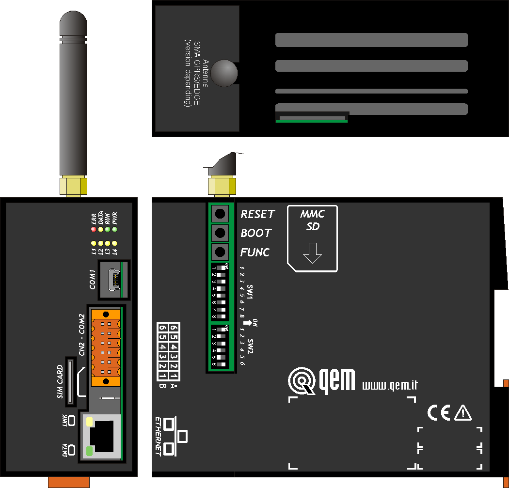
QBR1A is a LAN/GPRS router produced for the Teleassistance of QEM products.
It can be equipped with:Standard equipment 
8 system leds 
1 serial (RS232/TTL) COM1 (Use in combination with the accessory IQ009) 
1 multistandard serial (RS232/422/485) - COM2 
1 ETHERNET port 
1 Memory Card MMC/SD reader 
Clock calendar 
2 standard digital inputs 
2 digital outputs Optional equipment (Refer to the table Hardware versions) 1 multistandard serial (RS232/422/485) – COM3 PORT 
1 CANbus port 8 standard digital inputs 8 digital outputs 2.1 Product Identification

The Ordering Code provides the exact product features.
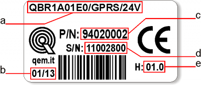
Make sure that the product features meet your requirements.2.1.1 Product Label
-
a - Ordering Code
-
b - Week made: indicates the week and year of manufacture
-
c - Part number: unique code that identifies an ordering code
-
d - Serial number: product serial number, different for individual product
-
e - Hardware release: version of hardware release
2.1.2 Hardware versions
There are currently 2 hardware versions:
Ordering code Features Part Number QBR1A01E0/0/24V Router LAN 94020001 QBR1A01E0/GPRS/24V Router LAN/GPRS 94020002 2.2 Product Configuration
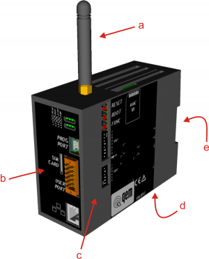
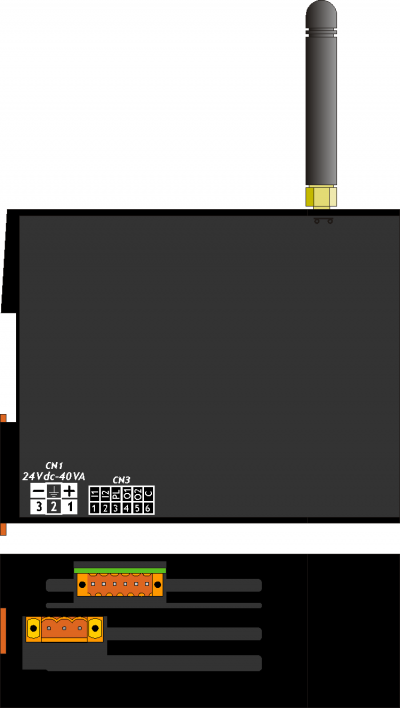
-
a = GPRS antenna
-
b = connections side
-
c = settings side
-
d = power supply and I/O connectors
-
e = connection for Omega DIN
2.2.1 Firmware versions
Version Description 01 Connection with QNet, with GPRS and LAN modem 3. Electrical features
3.1 General features
Weight (maximum hardware configuration) 
Box material Signal leds 8 System keyboards 24 Working temperature 0 ÷ 50°C Relative humidity 90% without condensation Altitude 0 - 2000m s.l.m. Transport and storage temperature -25 ÷ +70 °C IP protection IP20 3.2 CPU (F level technology)
RISC microprocessor (32 bit) Work frequency 200MHz RAM 16MB Flash 8MB 3.3 Dimensions

Lengths in mm 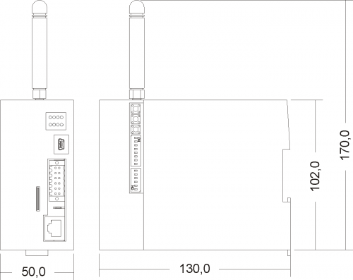
4. Electrica features and connections

4.1 Power supply

• The wiring must be installed by skilled personnel and with appropriate antistatic measures.
• Before handling the tool, disconnect the power supply and all the parts connected to it.
• To ensure compliance with EC regulations, the power supply must have a galvanic insulation of at least 1500 Vac.Power supplies available 24 Vdc Range 22 ÷ 27 Vdc Max. absorption DISTINGUERE I 2 MODELLI CN1 Terminal Symbol Description 
1 + DC positive power supply 2 TERRA Ground-PE (signals) 3 - DC 0V power supply 4.2 COM1 PORT (USB mini-B)
COM1 PORT Description 
COM1 serial port TTL standard electric used for connection to a QMove+ product (DIP 8 of SW1 OFF) or to the PC for the Bridge configuration (DIP 8 of SW1 ON).
In the latter case, you must use the IQ009 or IQ013 accessories.4.3 COM2 PORT (multistandard)
4.3.1 Connettore COM2 PORT
CN2 Morsetto RS232 RS422 RS485 Descrizione 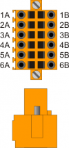
1A - - A Terminale A - RS485 2A - - B Terminale B - RS485 3A 0V 0V 0V Comune COM2 PORT 4A 0V 0V 0V Comune COM2 PORT 5A TX - - Terminale TX - RS232 6A Terra 1B - RX - Terminale RX - RS422 2B - RXN - Terminale RX N - RS422 3B - TX - Terminale TX - RS422 4B - TXN - Terminale TX N - RS422 5B RX - - Terminale RX - RS232 6B Terra 4.3.2 COM2 PORT standard settings
SW2 Num.
DipName
DIPSetting
of the DIPFunction 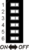
1 JP2 ON X1) X2) Termination RS485 2 JP3 ON X3) X4) Polarization RS485 3 JP1 ON X5) X6) 4 OFF ON OFF COM2 PORT standard settings selection 5 ON OFF OFF 6 OFF OFF ON RS485 RS422 RS232 4.4 ETHERNET PORT
ETHERNET PORT Description 
RJ45 connector.
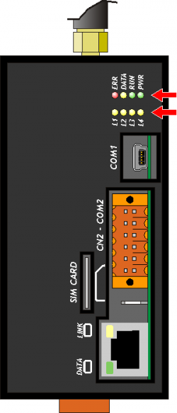
LED:
* LINK: green led = cable connected
* DATA: yellow led = data exchange (the flashing led indicates data communication between connected devices)4.5 MMC/SD
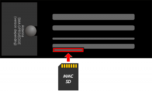 Memory card slot (highlighted by the arrow)
4.6 SIM CARD
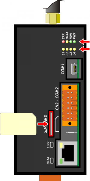
Slot for SIM card (highlighted by the arrow)
4.7 2 standard digital inputs and 2 standard digital outputs
The electrical features are given in paragraph Electrical features.
The connection examples are provided in paragraph Connection examplesCN3 Terminal Symbol Description

1 I1 Input I1 2 I2 Input I2 3 PL Common of the digital inputs 4 O1 Outputs O1 5 O2 Outputs O2 6 COM Common of the digital outputs 5. Connection examples
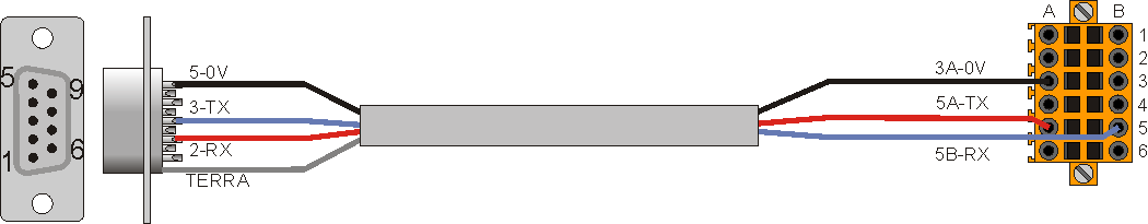
5.1 Connection between QBR1A (COM2) and the Qmove (C1, J1) Prog port
Qmove compatto (C1), Qmove integrato (J1) QBR1A 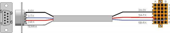
DSUB 9P-M
22010025WEIDMULLER B2L 3.5/12
22020159Set the dip switch SW2 as in table:
SW2 Num.
DipSetting
of the DIP1 OFF 2 OFF 3 OFF 4 OFF 5 OFF 6 ON 5.2 Connection between the PC and the QBR1A (LAN)
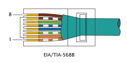
Is it necessary to use a direct ethernet cable as per specification EIA/TIA-568B-568B.


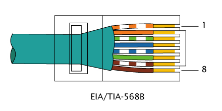
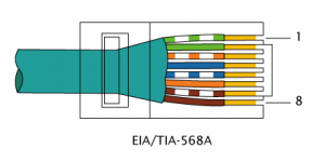
5.3 Connection between the QBR1A (LAN) and the QMove (LAN)
It is necessary to use an ethernet crossover cable specification EIA/TIA-568B-568A .
6. Settings, procedures and signals

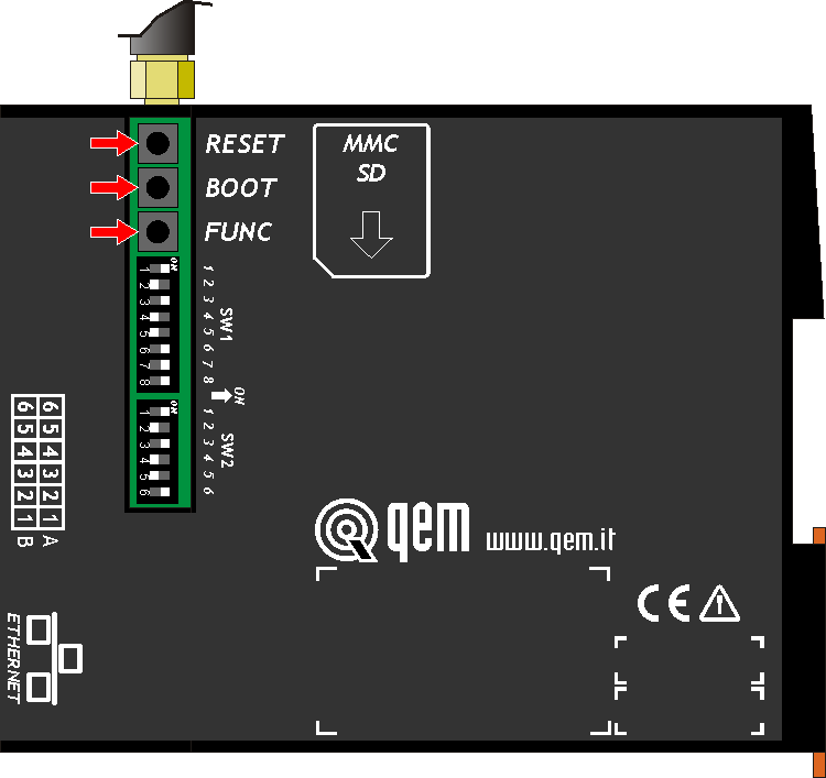
6.1 SW1 selector
SW1 Dip Name Function 
1 n.u. 2 n.u. 3 n.u. 4 n.u. 5 AUTOUPDATE ON = When you connect to the QNet network, checks for a new firmware and then download and upgrade. At the end system performs a Reboot. See section Upgrade Firmware 6 DIAGNOSTICS ON = Displays antenna signal strength in leds L1-L4 (see the section )7 n.u. 8 RESOURCE
CONFIGURATIONOFF = Select the COM1 (mini-USB) for communication with a QMove using the cable supplied with the accessories IQ009 or IQ013.
ON = Put the Bridge in Configuration mode, select the COM1 (mini-USB) for communication with a QMove using the cable supplied with the accessories IQ009 or IQ013.
!!! WARNING !!!
You must have special attention to the correct connection because the two different modes of operation reverse signals RX/TX then you could damage the electronic components.Default: only dips 5 and 6 ON
Verificare l'immagine del dip-switch: ON e OFF sono rovesci.
6.2 Led
The “PWR, RUN, DATA, ERR” leds are the system leds while the “L1, L2, L3 and L4” leds are used to display different data depending on conditions/application settings.
6.2.1 Alerts
6.2.1.1 Leds meaning
 Led ON
 Led OFF
 Led flashing
Led Color State Description PWR Green 
Bridge operative and communication module initialized. 
If this is the only lampegiante, led shows the status of communication module initialization. If DATA led flashing, reports that the Bridge is in edit mode Configurazione/Configuration Mode. RUN Green 
Bridge waitingEnabling the connection. Short blinking = Bridge waiting Activation command connection.
Slow blinking = Bridge to connect/disconnect to/from network QNet.Bridge connected to the network QNet. DATA Yellow If the PWR led is on, report the arrival the network information by QNet.
If the PWR led flashing, report that the bridge is in Configurazione/Configuration Mode.ERR Rosso If all other leds are in OFF, report an hardware error. See the section Hardware error codes.
If the PWR led is flashing, report an error during the initialization phase of the communication module. In the case of GPRS modem make sure you have inserted the SIM card and the PIN code.
If the RUN led is flashing, report an error during the QNet network connection. In the case of the GPRS modem make sure you have signal (see the section Antenna signal strength).
You can view a description of the error message by using the utility BridgeConfigurator.6.2.1.2 Hardware error codes
If a malfunction is detected when power on of any devices, the system hangs and the error is reported by the blinking of the led only
ERR while all the other leds remain in OFF.
The flashing numbers indicates the error type as to the following table:
Flashing numbers Error 1 Exception 2 FPGA 3 Media 4 Bootloader 5 Firmware 6 Resource 7 Modem 8 Memory write Each of these reports indicates a serious error. The product must be sent to customer support QEM. 6.2.1.3 Antenna signal strength
If you have a Bridge with GPRS modem antenna signal strength value (RSSI) you receive through the flashing of leds L1, L2, L3, L4.
L1 L2 L3 L4 Description 
No signal (-113 dBm o meno) o scarso 
-111 dBm < RSSI < -77 dBm
Insufficient signal-77 dBm < RSSI > -69 dBm
Sufficient signal-69 dBm < RSSI > -63 dBm
Good signalRSSI > -63 dBm
Optimal signal
In some cases, employees by the operator, this message appears even when no signal.
6.3 Keys
 - Nel Bridge il RESET è all'esterno, quindi BOOT e FUNC.
Name Description  FUNC
FUNC If the condition of Enable the connection satisfied, pressed for at least 1 second to activate the QNet network connection (the RUN led flashes). BOOT Pressed at power ON, set the instrument in Boot state, allowing access to firmware update. RESET The system gets restarted. 7. The QNet network
The QNet network provides the structure for connecting two or more QRM nodes (Qem Resource Manager) through the Internet network.
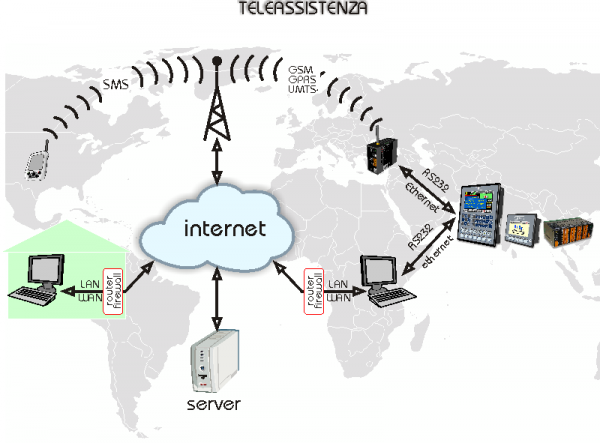
7.1 The QRC server
The QRC (Qem Resources Control) server, is a server QEM that manages the connection permissions between the various network QNet nodes.
7.2 The QRM-QRMB
The QRM (Qem Resource Manager) or the QRMB (Qem Resource Manager for Bridge) are the Nodes that share, using the resources, the means to access more tools Qem.
7.3 The network QNet resources
Are considered resources all communication channels provided by various nodes QRM-QRMB to connect the different QMove systems.
7.4 Directions for network administrators
The connection to the QNet network using an encrypted protocol.
On a LAN network, therefore every Bridge will open a connection TCP/IP OUT on the gate 8005 way the server QEM QRC at the address qrc.q-move.eu (188.95.77.82). To enable the auto-update the firmware it is also necessary that the Bridge can take advantage of the FTP Protocol (gate TCP/IP 20-21) always log on to the server at the address in QEM QRC qrc.q-move.eu (188.95.77.82). To enhance safety on the LAN every other type of communication can be blocked.8. General information of operation
8.1 Introduction
This chapter will introduce some concepts and describes some product operations. These contents are partly related and implemented in the firmware.
8.2 The Bridge resources
Are considered resources all the comunication channels provided by the Bridge to connect more QMove systems. The channel word will be synonymous with resource.
All serial port (COM) on the Bridge are resources. In the base versione there are two serials: COM1 and COM2. With the expansion is available the serial: COM3.
In the case of presence of the Ethernet port, 3 channels of communication are generated: LAN1, LAN2, LAN3.
In the maximum configuration, the Bridge can have 6 channels of communication, that can be connected to a QMove system.
8.3 The Manager channel
Is there a particular communication channel, used exclusively by the QNet network called Manager.
It safeguard all communication to the QRMB.8.4 Conditions and Enables
To ensure that the Bridge run is the status of the connection if desired Enable the connection.
By default, the condition is satisfied as long as the I1 input is active. When the condition Enable the connection is satisfied, for default, the O1 output is active.8.5 Operating States
This section describes the operating States.
8.5.1 Boot
The Boot phase, is the first to be performed after switching on (or the reset) of the instrument.
During this phase runs a scan of all leds.
If an hardware failure is detected, the system hangs and only ERR led flashes indicating the type of error (see the section Hardware error codes).8.5.2 Recognition and Hardware configuration
The Bridge check that all devices are operational.
The phase is signalled by the blinking of the PWR led only.
In case of error the ERR led starts blinking.
One of the possible errors, in the presence of the Modem 3G module, is the non-inclusion of the SIM CARD or the PIN error (parameter gprs1_pin).8.5.3 Connection request waiting
The Bridge is waiting to connect to the network QNet network.
The PWR led is steadily lit.
The RUN led, if in OFF, indicates that the conditions of qualification for the connection isn't verified.
When the enable conditions are met, the RUN led start flashes briefly and the O1 output is active.8.5.4 Connection to a QNet network
The Bridge is connecting to the QNet network.
The PWR led is in ON and steadily lit and the RUN led is flashing continuously.
8.5.5 Firmware Upgrade
If the SW1 dip n°5 (AUTOUPDATE) is ON, before connecting to the QNet network, the Bridge check if a firmware update.
If it discovers an new firmware, it gets downloaded.
This stage is marked by a continuous flashing of L1, L2, L3 e L4 leds.
• At the end of the download the Bridge goes in the BOOT state to store in the flash the new firmware.
• DO NOT TURN OFF the Bridge.Finished updating, the Bridge will automatically reboot.
8.5.6 Error
The error message occurs with the ERR led.
The Bridge, in some cases, attempts to do so failed.8.6 Configuration
8.6.1 Bridge System Info
The following lists contain information parameters of Bridge, Bridge System Info, that can be read by the application Utility QRM BridgeConfigurator.
Name Type Default Description Firmware name stringa QBR1A Nome del firmware in uso. version string 1.0.1 Current firmware version. serial number entire 12345678 Serial Number of the connected Bridge. checksum string 12345678 Checksum of the used firmware. Timedate date date 20120131 Data used, in the form YYYMMDD.
Example, 20120131, 31 gennaio 2012time time 165513 Time used, in the form hhmmss.
Example, 165513, 16.55.13Module data: LAN Device LAN string 2 Indicates that the connection to the server QRC is: LAN manufacture string Producer model string Model mac string MAC address dhcp entire 0 DHCP Type ip address ip 192.168.0.253 IP address netmask ip 255.255.255.0 Netmask gateway ip 0.0.0.0 Gateway address Module data: modem 3G Device 3G string 2 Indicates that the connection to the server QRC is: LAN manufacture string Producer model string Model fw string Firmware version imei string IMEI code iccid string ICCID code imsi string IMSI code Features mtu_qrm entire Specifies the MTU value of the QRMB server mtu_bridge entire Specifies the MTU value of the Bridge channels_com entire 2 Specifies the available COM channels channels_tcp entire 0 Specifies the available TPC channels 8.6.2 Bridge System Settings
Lists the configuration parameters of the Bridge, Bridge System Settings, that can be modified by the application QRM BridgeConfigurator Utility.
Name Type Default Description Section QRM-Bridge qrc_ip string 188.95.77.82
qrc.q-move.euIP Address/Hostname of the QRMB server that the Bridge connects. qrc_port number 8005 QRMB server TCP port number to which the Bridge connects. Section FTP ftp_ip string 188.95.77.82
qrc.q-move.euIP Address/Hostname of the FTP server athat the Bridge connects for firmware update. ftp_port number 21 FTP server TCP port number ftp_user string User name for FTP server authentication.
If empty, it is automatically generated by the Bridge.ftp_pass string User password for authentication to the FTP server.
If empty, it is automatically generated by the Bridge.Section ETH (valid only with network interface) eth0_mac string 00:00:00:00:00:00 MAC address of Bridge network interface (if present). eth0_dhcp number 0 Type of DHCP Client setting:
0 = disableeth0_dhcpip string 0.0.0.0 IP Address/DHCP Hostname server .
(currently not supported)eth0_ip string 192.168.0.253 IP Bridge address. eth0_nm string 255.255.255.0 Network mask. eth0_gw string 192.168.0.1 IP gateway address. eth0_dns1 string 0.0.0.0 DNS1 IP Address.
(currently not supported)eth0_dns2 string 0.0.0.0 DNS IP Address.
(currently not supported)GPRS Modem section (valid with the modem) gprs1_pdp string ibox.tim.it GPRS context. gprs1_pin number PIN code of the SIM (normally empty or 0000). module_pref number 0 Default module:
With the Bridge who have both Ethernet interface and GPRS, indicates the module that is used when connecting to the QRC.
0 = LAN
1 = GPRSAdditional functionality fn_autoconnect number 1 Auto-login:
0 = Disable (default)
1 = At the power ON of the Bridge the connection operations are enabled (simulates I1 on).
2 = At the power ON of the Bridge is immediately connected to the QNet network, if the ratings are valid (simulates I2 on).
3 = At the power ON of the Bridgee is immediately connected to the QNet network (simulates I1 and I2 on).fn_i01 number 0 Input 1 function:
0 = Abilitazione alla connessione (default).
Stato: Continuo.
Con l'ingresso alto, vengono abilitate le operazioni di connessione.
Con l'ingresso basso, vengono chiuse eventuali connessioni in essere ed inibite le successive (anche WAKE-UP).fn_i02 number 0 Input 2 function:
0 = Enable/Disable connection (default).
State: Impulsive. Minimum duration of command: 1 sec.
The activation of the input will cause the network connect/disconnect procedure to the QNet network.
If FunctionI1 is 0, the input issubject to the consent of I1 (active).fn_o01 number 0 Output 1 function:
0 = Ready connect (default).
Output OFF: if I1 is OFF or the start up conditions are not valid.
Steady output: if I1 is in ON and if all start up conditions are valid (SIM ok, network presence, etc…).fn_o02 number 0 Output 2 function:
0 = Connection state (default).
Output OFF: Connection is not present or in progress.
Steady output: Connected to the QNet network. -
-