Inhaltsverzeichnis
5 Axis Marble Bridge Saw: User Manual
 .
.
| Document | P1P51FB30-001Q | ||
|---|---|---|---|
| Description | User manual | ||
| Drawn up | Riccardo Furlato | ||
| Approved | Draft | ||
| Link: | http://www.qem.eu/doku/doku.php/en/strumenti/qmoveplus/j1k31/mdu_p1k31fb30-002q/funzionamento | ||
| Languages | English | ||
| Release | Description | Notes | Date |
| 01 | New Manual | 22/08/13 | |
All rights reserved on this manual. No part of this document can be copied or reproduced in any form without prior written authorisation. QEM does not insure or guarantee its contents and explicitly declines all liability related to the guarantee of its suitability for any purpose. The information in this document can be changed without notice. QEM shall not be held liable for any error or omission in this document. QEM® is a registered trademark.Microsoft® and MS-DOS® are registered trademarks and Windows® is a trademark of Microsoft Corporation.
Index
-
1.1. Typical work results
-
4.1. Homing
-
4.2. Main Menu
-
4.3. Machine Data
-
5.1. DXF file import
-
5.1. Drawing Editor
-
5.1.1. Drawing tools
-
5.1.2. Symbols on the drawing
-
5.2.2. Work Cycle - Curved Profiles
-
5.2.3. Work Cycle - Columns
-
5.3. Work Cycle - Tops
-
5.3.1. Work Cycle - Tops > Milling
-
5.4. Work Menu
-
5.5. Work - Multiple cuts
-
5.6. Work - Tile Cuts
-
5.7. Work - Tilted Cuts
-
5.8. Work - Profiles
-
5.8.1. Profile with straight cuts
-
5.8.2. Profile with curved cuts
-
5.9. Work - Tops
-
5.10. Work - ISO G codes
-
5.11. Start Cycle
-
6. Alarms
-
6.1. Alarm history
-
6.2. Warning Messages
-
7. Diagnostics
1. General Characteristics
Description
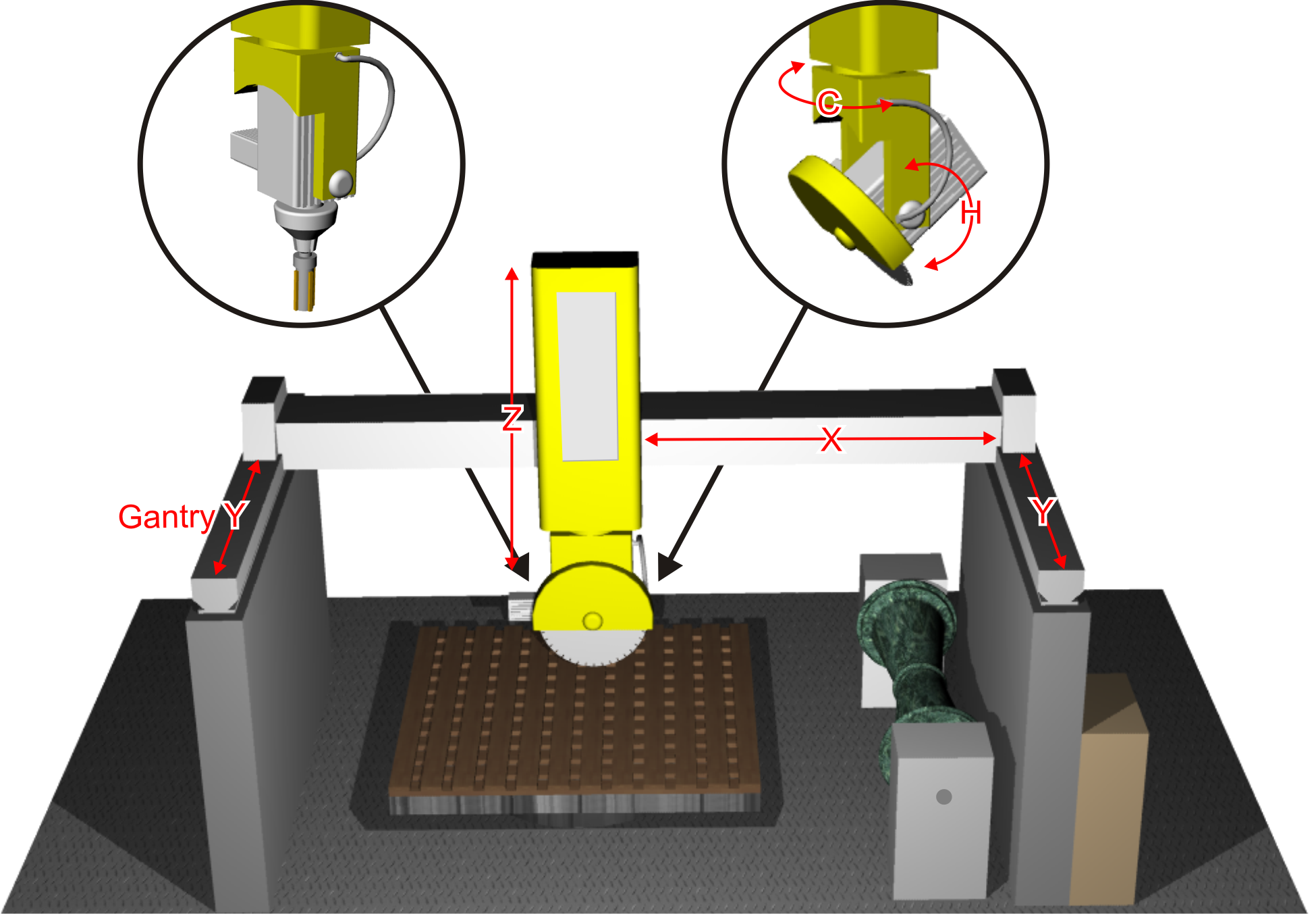
The P1R31FB30 - 002q software can be installed on the Qmove+ J1.P31 - J1.P51 - J1.P71, J1.K31 integrated HMI+PAC or C1-R31-FG30 cabinet PAC plus A1-HMI-QC104 or A1-HMI-QC121 HMI. It is designed to control a bridge saw with 5 axes, for marble and granite. The salient features of the P1R31FB30 - 002 are described below.
Axes
Interplated Axes:
-
Axes X, Y, Z for the cartesian motion of a disk or drill mandrel.
-
Axis C for the disk rotation.
Other Axes:
-
Axis H for the disk tilt.
-
Gantry control of Axis Y
All axes are controlled by PID on space (brushless motors with servo drives and brushless motors)
Work Processes
-
Flexible work parameters linked to drawings, easy-to-use for marble workshops
-
Semiautomatic functions for positioning the axes and for single cuts.
-
Multiple cuts for slab cutting, with rotating head (C) for tile cutting.
-
Straight, curved and arc profiling with horizontal or vertical disk.
-
Step cutting with disk (for hard stone).
-
Straight profile finishing, with disk face.
-
Shape and circular cutting of tops.
-
Work cycles for drain slopes and holes.
-
Work cycles for recessing.
Drawing
-
User-friendly, simple MiniCAD editor for drawing, an embedded CAD software.
-
Optimised DXF file import and integration from PC by the “Profile Importer” conversion software (optional).
Work modes
-
Repeat the programmed shape.
-
Set the precision of the finishing.
-
Modify the speed of disk motion during the work cycle.
-
Compensation of the disk thickness and the disk diameter.
Accessory functions, messages and alarms
-
Language select, with optional languages in any alphabet (chinese, cyrillic, arabic, etc).
-
View the profile and the disk position, during the work cycle.
-
View of disk and mandrel speed during operation
-
Diagnostics of the inputs and the outputs.
-
Backup and restore of the data on non volatile memory (FLASH EPROM).
-
Messages for active faults, for easy troubleshooting.
-
Help Messages.
-
Modem for remote support, updates, file import.
Optional Features (some not documented in this manual)
-
Copying by photocell from a cardboard shape or black on a whiteboard.
-
DXF file import and integration in Qem MiniCAD
-
ISO G code execution, for extra CNC functions (texting, low-relief sculpturing)
-
Lathe mandrel speed
Modbus Interface
-
The USER serial port can create a MODBUS RTU (RS485) network, for reading the disk rpm and the absorbed current of the disk.
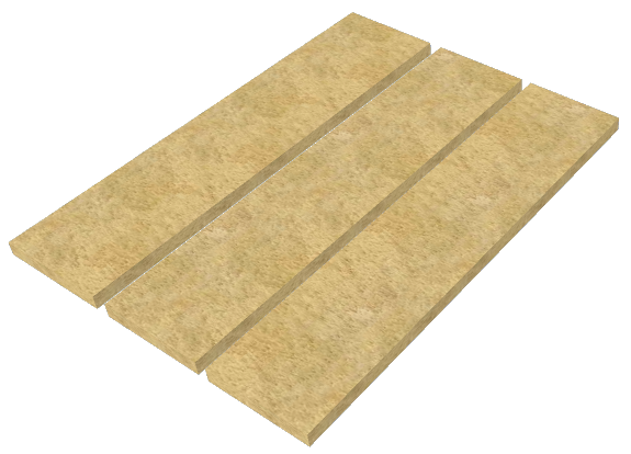
1.1 Typical work results
 Multiple cuts | 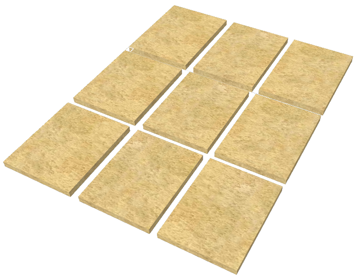 Tile cuts | 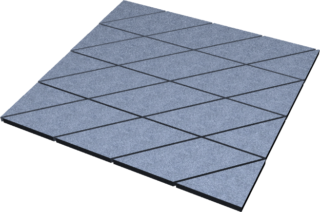 Cross tile cuts |
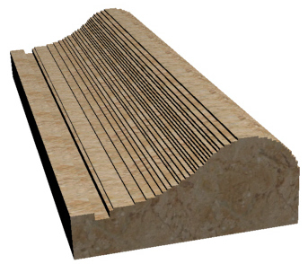 Profile roughing | 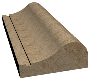 Profile finishing | 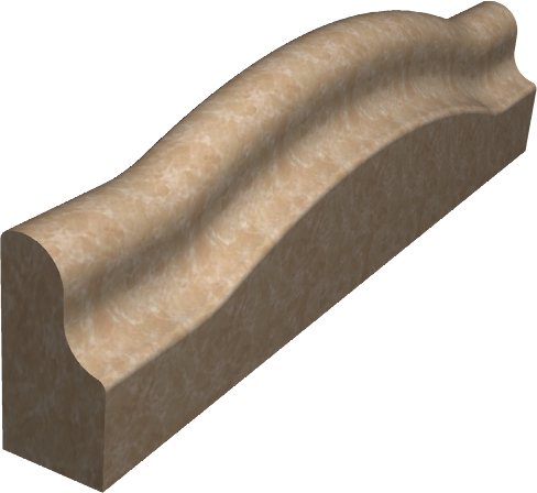 Curved profile roughing |
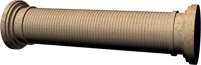 Column roughing | 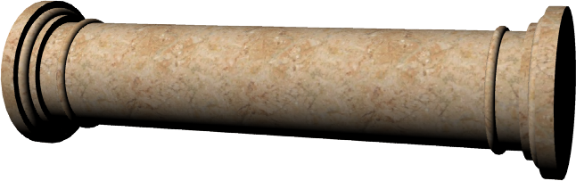 Column finishing | 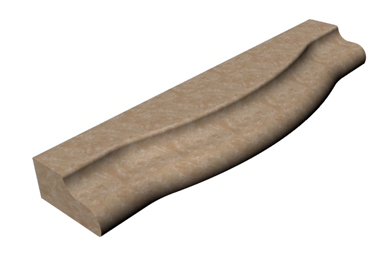 Horizontal profile roughing |
 Top roughing | 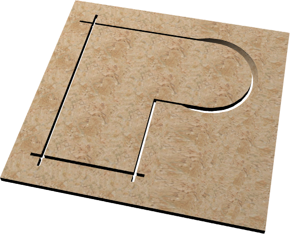 Top cutting | 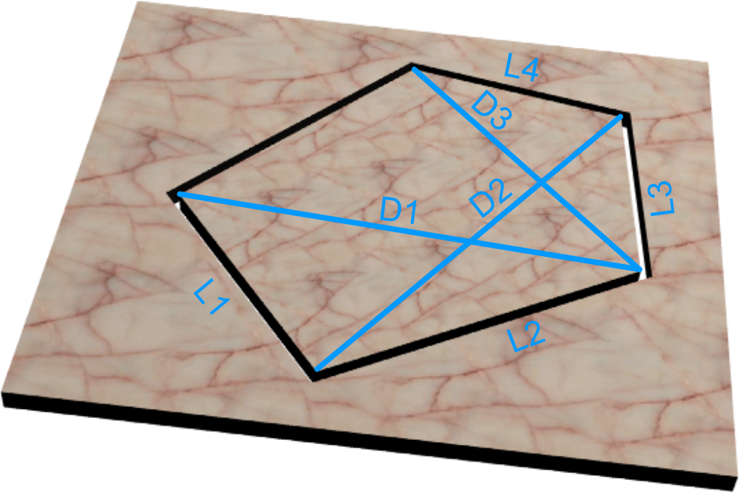 Spiral stairs |
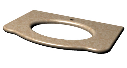 Top milling | 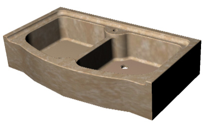 Sinks & drains | 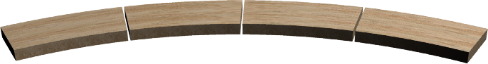 Arc tiles |
 G-Code texting |  G-code relief |  G-code texting |
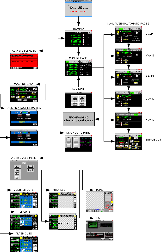
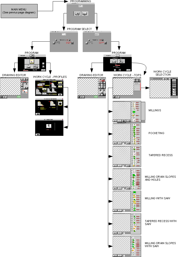
2. Screen flow chart
3. Function Keys and Led's
| Key | Function | Led | |
|---|---|---|---|
| F1 |  | START CYCLE OR HOMING Start a cycle or the homing procedure. | Automatic Cycle OFF: stopped. ON: in course. |
| F2 |  | STOP Stop a cycle and the homing procedure. | not used. |
| F3 |  | SEMIAUTOMATIC Enable the semiautomatic mode, for one axis positioning. After the single positioning is returns to manual. | Semiautomatic OFF: not in mode. ON: in mode. |
| F4 |  | WATER Open/closed The water valve opens automatically, when the automatic cycle starts. | Water SV: OFF: shut. ON: open. |
| F5 |  | ALARMS. Open the active alarm screen. | Alarm Message OFF: no alarm. ON: alarm. |
| F6 |  | EXIT Exit the screen and return to the previous screen. | not used |
Standard Buttons and Commands
1. Yellow settings in Yellow can be modified by. Press the setting and confirm with ![]() .
.
2. Multiple choice parameters - to select press ![]()
3.  go to previous screen and
  go to next screen
4.  General Setup screens (protected by password)
4. The Startup Screens
The start screen
| Icon | Description | |
|---|---|---|
 | Top bar with Program code | |
 | Select language Standard languages: ITALIANO - ENGLISH (all languages/alphabets with Unicode) |
|
 | Enter program | |
 | Backup - Restore | |
Homing

Manual

4.1 Homing
 |
| Key | Description |
|---|---|
| START HOMING. |
| STOP HOMING. |
ALWAYS run the Homing procedure before going from HOMING to MANUAL.
Failure to do the Homing will limit the machine operation. These limits are in the Setup section protected by password.
4.2 Main Menu
 |  | Work menu |
 | Programming menu | |
 | Diagnostics | |
 | Manual/semiautomatic | |
 | Homing | |
 | Machine Data |
4.3 Machine Data
MAIN MENU Press 

 | Disk RPM reading. |  | Press for RPM setup in automatic mode |
 | Disk absorbed current | AMP MAX | Maximum absorbed current (press setting to change) |
 | Disk thickness (press setting to change) |  | Disk diameter (press to go to setup) |
 | Self-learn disk diameter |  | Tool diameter screens |
| Z | Actual Z-axis position | MIN Z | Set Z-axis down position |
| SAFE QUOTA | Self-learn safe Z-Axis down position | ||
 | Safe quota ON and self-learn |  | Safe quota OFF |
 | Disk auto speed table (password) | ||
Press 


| Ø | Disk / Tool diameter.   Change diameter. Change diameter. | |
| MARBLE / GRANITE | Select the type of stone | |
| A speed is given for the diamenter and type of stone. The speed is taken from the setup table | ||
| RPM AUTO | Preset RPM based on diameter. The setting can be changed by 30%. The setting is a 0-10 Vdc given by: Vdc = (10 * RPM AUTO) / MAX DISK RPM. See generic setup for MAX DISK RPM (parameter PG-04) | |
DISK and TOOL SPEED Tables
Press  and enter the password (default = 462)

Set the diameters and related speeds for the two types of stone.
4.4 Manual / Semiautomatic
MAIN MENU > Press

Press ![]() in any screen to view the 5 axis positions (distance from zero) and speeds.
in any screen to view the 5 axis positions (distance from zero) and speeds.
To open the axis pages, Press ![]()
![]()
![]()
![]()
![]()


Here you can move the axis as the base page and further you can start a moving to a quota.
Interpolation mode. | No interpolation mode. |
| The Axis motions are coordinated together, based on the C-Axis and H-Axis of the head. Valid for manual and semiautomatic operation. | Each Axis moves individually and independent from any other Axis. |
Procedure:
1. Press semiautomatic  .
.
2.  will show and the function key LED lights up.
3. Press the start function button  .
.
-
TARGET
 : Axis goes to target setting in „MOVINGS QUOTA“.
 -
INCREMENTAL: Axis goes to the sum of POSITION + „MOVINGS QUOTA“.
-
RELATIVE ZERO: Axis goes to selflearn zero position.
| Reset the axis position and selflearn a new zero position | |
| Disk thickness correction ON-OFF. | |
 | The minimun safe position is the setup quota. |
 | The minimun safe position is the selflearn quota. Press to selflearn Z position for the minimun safe quota. |
Press ![]() ⇒
⇒
 .
.
Single cut screen:
| Press the button to selflearn the quotas. | |||
 | X-Axis position of start cut. |  | X-Axis position of end cut. |
 | Single cut. |  | Step cuts in multiple depth increases. |
| Cut depth position. | |||
| Material type. Up to 10 materials can be stored. | |||
| Depth increase at start cut. | Depth increase at end cut. | ||
| Final depth increase to complete the cut. | Speed during when the final depth cut. | ||
To start the SINGLE CUT press Semiautomatic (LED lights up and is shown). Then press Start .
IMPORTANT. IN SEMIAUTOMATIC MODE THE AXES CAN ONLY MOVE ONE AT A TIME. FOR THE NEXT POSITIONING (OR SINGLE CUT), RE-START THE SEMIAUTOMATIC MODE.
5. Programming and Work Cycle
MAIN MENU > Press  for Programming
 |  | Profiles |
 | Tops |
Select a program
 | PROGRAM N. | Press & enter number |
| PROGRAM NAME | Press & enter name | |
 | Open the program | |
 | Open the Program and preview list |
Select from preview
 | Press a program to select | |
| Filter by name | ||
 … …  | Scroll the list | |
| Open the program. |
 |  | CAD EDITOR |
 | WORK CYCLE | |
 | Go to WORK PROCESS | |
 | Save a Program | |
 | Import from Memory card |
5.0.1 DXF file import
N.B. DXF Import is only possible with the optional Qem Profile Importer software
(see manual FIXME insert link)
MMC/SD card: press
Ethernet: transmit the file from PC only in this page, will flash and press to save.
5.1 Drawing Editor
Press  to open the Drawing Editor screen
 Top Editor |  Profile Editor |
A Drawing is a series of Sections. Section 2 starts at the end of section 1.
 Fit and center Fit and center |  Zoom in Zoom in |  Zoom out Zoom out |
| Select drawing/section (section=red) |  Section properties Section properties |  Delete the drawing Delete the drawing |
 Add a new drawing. Add a new drawing. |  Delete the selected drawing. Delete the selected drawing. | |
 Add a section Add a section |  Insert a section Insert a section |  Delete the section Delete the section |
 Copy a Profile Copy a Profile |  Copy a drawing Copy a drawing |  Rotate a drawing Rotate a drawing |
 Mirror a Profile Mirror a Profile |  Mirror a drawing Mirror a drawing |  Move a drawing Move a drawing |
 Scale A drawing Scale A drawing |  Parallel Trace a drawing Parallel Trace a drawing |
| Profile Editor - Plane selector. Before drawing the profile, select a vertical or horizontal disk. A specific screen will appear. |
||
| Vertical disk |  Profile on the YZ plane. Profile on the YZ plane. | The shape of the cuts. |
| Horizontal disk | The shape of the cuts. |
|
There must be always a drawing in YZ plane. | If there is no drawing for the XZ or XY plane a profile is not drawed, the cut will be straight. Just set the cut start and end for the work cycle. |
|
5.1.1 Drawing tools
| Press Add , Insert or Modify |
||
Enter the coordinates by HMI keyboard or by selflearn axis (press  next to each setting.) next to each setting.)Slab Sizing by Laser. Acquire the shape of a slab by the self-learn function. Move the laser to points on the slab and acquire the shape. The shape is shown on the screen, to confirm that the drawing enters the size of the slab. |
||
Line |  | Enter two coordinates of the end point (incremental or absolute) |
Tangent line |  | Enter first coordinate: |
Enter second coordinate:  |
||
Enter L = length  |
||
Arc |  | Enter two coordinates of the end point, and the radius MINIMUM: the minimum radius |
 clockwise arc clockwise arc 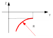 |
||
 anticlockwise arc: anticlockwise arc: 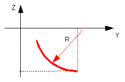 |
||
3-point Arc |  | Enter two coordinate values of the end point and the middle point. Ex.: |
| Tangent Arc  |  | Enter two coordinates of the end point: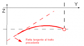 |
Transfer | Transfer = section with no cut | Enter two coordinates of the end point: |
| IMPORTANT: Transfers must always be downward, before a cut |   |
|
| Drawing macros. Functions to make a complete drawing. Enter the drawing dimensions. | ||
Rectangle | |
|
Regular poligon | |
|
Kitchen top | |
|
Ellipse | |
|
Arc sectors | |
|
Spiral staircase | |
|
| Start of drawing | The start point is at the origin of the axes. Enter a point (negative) in the parameter Z0 (main editor screen) to lower the start point |  |
| Undercut on profile | PROFILE ONLY An undercut is automatically corrected. | 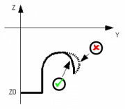 |
| Absolute or Incremental quota | The co-ordinates of a new section can be absolute or incremental |  Absolute = co-ordinates from origin Absolute = co-ordinates from origin Incremental = co-ordinates from end of drawing Incremental = co-ordinates from end of drawing |
5.1.2 Symbols on the drawing
The following symbols are used on the drawing.
| Symbol | Meaning |
|---|---|
 | The selected section is shown in red. |
 | If the selected section is a 3-point arc, the intermediary point is shown. |
 | The transfer section is always blue. |
| No symbol | If the drawing does not have any symbols, the section is the last. |
5.2 Work cycle - Profiles
Press 
 |    |
 Finishing screen or Cut parameters.Only available on straight profiles.
| BLOCK DIMENSIONS |  | Check the profile enters the block (grey = stone block) |
|
| SURPLUS MATERIAL | VERTICAL BLADE | HORIZONTAL BLADE | SM = extra material on the profile |
| CUT DIRECTION |  Simple cut Simple cut |  Two-way cut Two-way cut |
|
| Y-AXIS DIRECTION | If the profile is drawn as follows: |  Y = Negative direction ? blue profile Y = Negative direction ? blue profile Y = Positive direction ? red profile Y = Positive direction ? red profile |
|
| CUT MODE |  | Press  to set to set |
|
| CUT MODE |  |  | Cut mode 0 D = Cut spacing on the profile contour Medium speed - Medium precision |
 |  | Cut mode 1 D = Cut spacing on the Y-Axis Top speed - Low precision |
|
 |  | Cut mode 2 D = Cut spacing on profile contour Disk perpendicular to profile contour Low speed - Top precision |
|
| CUT PREVIEW |  |  |
|
| REPEAT PROFILE | VERTICAL BLADE | HORIZONTAL BLADE |
|
| NP = Number of profiles to cut | SP = Spacing between two profiles. This accounts for the blade thickness. |
||
5.2.1 Work Cycle - Profile Finishing
 |  |
| GENERAL PARAMETERS |  | RH = X-Axis steps V = Max speed for interpolated motion. OZ = extra material for removal |
| OFFSET | VERTICAL BLADE | HORIZONTAL BLADE |
| STRATEGY |  | OFF = No finishing ON = Finishing after profiling. ONLY = Only finishing and no profiling. |
5.2.2 Work Cycle - Curved Profiles
 |
 Go to Profile parameters Go to Profile parameters |
Set the maximum interpolation speed of the cuts. This setting can be adjusted by an override during the work.
5.2.3 Work Cycle - Columns
N.B. Column work is only available if the lathe mechanics are installed


5.3 Work Cycle - Tops
Press > 
Match adrawing to a work cycle. The righthand box lists the work cycles in a work program.
Touch a Work Cycle to select it and see its related drawing.
| First icon | |
|---|---|
| The work cycle is not in work program, or not programmed | |
| The work cycle is included in work program | |
| Second icon | |
| The work settings must be entered | |
| The drawing has been changed, check the data! | |
Open the previous or next 5 work cycles. |
|||
| | Add a new work cycle. | | Delete the work cycle. (Not the drawing) |
| | Work cycle properties. A page is opened for each work cycle, to enter the settings. |
||

5.3.0.1 Work Cycle - Tops > Milling
Press 
  |  |
| Symbol | Description | Symbol | Description |
|---|---|---|---|
 | Preview of work cycle on drawing |  | DU (Tool diameter) |
 | SI (Initial Surplus): Distance of first cut from real cut |  | PA (Approach Cut): Distance of next cuts to reach the real cut |
 | VT (Cutting Speed) |  | VZ (Z- Speed): Downstroke speed |
| LU (Lh/Rh Tool) | |||
 | tool cuts on left side |  | tool cuts on right side |
| TP (Type of cut) | |||
 | SINGLE: Cut made in a single stroke |  | MULTI: Cut made of several steps |
 | PZ(Z Step): Multi type of cut = the depth of the Z axis each step. | ||
| TI (Cut Slope): the cutting depth has a slope direction | |||
| depth increase = X axis decrease | | depth increases = X axis increase | |
| depth increase = Y axis decrease | depth increase = Y axis increase | ||
 | MI(Minimum Depth): minimum depth of the slope |  | MA(Maximum Depth): maximum depth of the slope |
| If MI = MA, the cut is level. The cut can be obtained by single or multi cut, set in parameter, TP | |||
 | DI (Direction): Select the tool direction (clockwise/anticlockwise) Only for closed shapes | ||
| PP = | PP (Start Point): Select the start point | Closed shape: any point | Open line: only an end |
ENTRY: Select the start point, add the tool lead in | EXIT: Select the start point, add the tool lead out |
||
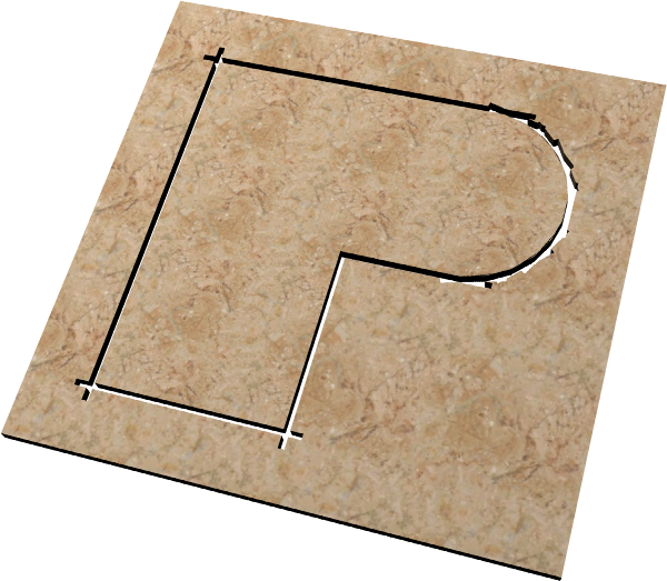
A typical tool path for a rectangular recess:
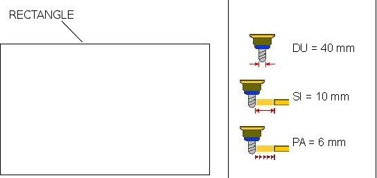
Set SI (Initial Surplus) and PA (Approach Path). The tool follows the paths and approach the final path for the final size.
PA (Approach Path) is the material removed during each path.
Try with shaped tools. First cut a rough geometry with a simple bit, leaving extra material (SI).
Change the tool and add PA.
Repeat the work cycle with PA.
| Milling bit |  | Roughing step |  |
|
| Shaped bit |  | First step | Second step | Final step |
 |  |  |
||
5.3.0.2 Work Cycle - Tops > Pocketing
Press 
 |  |
| Symbol | Description | Symbol | Description |
|---|---|---|---|
| Preview of work cycle on drawing | | DU (Tool diameter): set the diameter of the bit. |
| MF(Drill Mode) | |||
 | CONTINUOUS: no operator confirmation to drill holes. |  | PAUSE: press START to drill the next holes. |
 | PB(Edge): hole spacing along the edge. |  | PX(X-Axis): hole spacing along the X-axis. |
 | PY(Y-Axis): hole spacing along the Y-axis. |  | SM(Space): distance between holes and edge of the drawing. |
| MO(Mode) | |||
 | EDGE: holes along inside edge. | ||
 | HOR.IN.: horizontal layout of holes. |  | VER.IN: vertical layout of holes. |
 | EDGE+HOR.IN.: inside edge and then horizontal layout. |  | EDGE+VER.IN: inside edge and then vertical layout. |
P1 | the first depth of drilling | V1 | the first drilling speed |
P2 | Final drilling depth | V2 | Final drilling speed |
| The depth, P1, must be less than P2 | Speed, V1, is normally less than V2 | ||
5.3.0.3 Work Cycle - Tops > Tapered Recess
Press 
 |    |
| Symbol | Description | Symbol | Description |
|---|---|---|---|
| Preview of work cycle on drawing | | DU (Tool diameter): set the diameter of the bit. |
 | PA(Spacing): hole spacing | MO (Mode) | HORIZONTAL: spacing on Y-axis VERTICAL: spacing on X-axis SPIRAL: concentric spacing |
| TI (Cut Slope): the cutting depth has a slope direction | |||
| depth increase = X axis decrease | | depth increase = X axis increase | |
| depth increase = Y axis decrease | depth increase = Y axis increase | ||
| MI(Minimum Depth): minimum depth of the slope |  | MA(Maximum Depth): maximum depth of the slope |
| If MI = MA, the cut is level. The cut can be obtained by single or multi cut, set in parameter, TP | |||
| MO(Mode) | |||
 | HORIZONTAL: tool paths along the X-axis. |  | VERTICAL: tool paths along the Y-axis. |
 | SPIRAL: tool paths in concentric circles. |  | SM(Surplus Material): extra material along inside edge. |
| | VZ (Z- Speed): downward speed | | VT (Cutting speed): cutting speed |
| TP(Cut Mode) | |||
 | SINGLE: cut made in one stroke. |  | MULTIPLE: cut made in several steps. |
 | PZ(Z Step): if the Z Step = Multiple, depth increases of the Z-axis from one cut to another | ||
5.3.0.4 Work Cycle - Tops > Milling Drain slopes
Press 
 |  |
| Symbol | Description | Symbol | Descrption |
|---|---|---|---|
 | BO(Edge Depth): the depth along the edge. |  | CE(Centre Depth): the depth at the drain centre. |
 | RE(Outside Radius): radius of the external reference circumference. | ||
| RI(Inside Radius): radius of the internal reference circumference. | |||
| RS(Drain Radius): radius of the drain. This circumference has the depth at the centre. | |||
 | PB(SPACING AT EDGE): Equal path spacing on the edge. |  | PR(OUTSIDE SPACING): Equal path spacing on outside reference circle |
| | DU (Tool Diameter): diameter of the drill bit. | | SM(Surplus Material): extra material left along the inside edge. |
  | CX e CY (Centre (X, Y)): drain centre coordinates Reference to piece or to drawing. |
||
| | VZ (Z- Speed): Tool DOWN speed | | VT (Cut Speed): Work speed. |
A typical tool path, during drain recessing: | Tool path | |
| Depth at edge | ||
| Solid shape | ||
| Drain radius | ||
| Inside radius | ||
| Outside radius | ||
| Depth at center |
5.3.0.5 Work Cycle - Tops > Disk cutting
Press 
 |  |
| Symbol | Description | Symbol | Description |
|---|---|---|---|
| LU (Lh/Rh Tool) | |||
 | tool cuts on left side |  | tool cuts on right side |
| CT(Cut Type) | |||
| Cuts with only one pass. | Cuts with multi passes. | ||
| SL(Slab thickness). | IB(Engraving desk). | ||
| | SM(Surplus Material): extra material along inside edge. | IT(Crossing cuts). |
|
| ST(Safe shortening cut). | BC(Begin cut deepness increment). | ||
| EC(End cut deepness increment). | QA (Arc Quota). Value to cut the arc with a rough mode. |
||
| AT (Arc type) | |||
| Arcs are cutted with interpolated 3 axes movement. | Arcs are cutted with rough mode (see QA parameter). | ||
5.3.0.6 Work Cycle - Tops > Disk Tapered Recess
Press 
 |
| Symbol | Description | Symbol | Description |
|---|---|---|---|
| CT(Cut Type) | |||
| Single cuts. | Step cuts. | ||
| | SM(Surplus Material): extra material along inside edge. | BC(Start cut depth increase). | |
| EC(End cut depth increase). | PS(Cuts spacing). Cut spacing. |
||
| TY (Cut Slope): Slope direction of the cutting depth | |||
 | depth increase = X axis decrease |  | depth increase = X axis increase |
 | depth increase = Y axis decrease |  | depth increase = Y axis increase |
| DU(Minimum Depth): minimum depth of the slope | DD(Maximum Depth): maximum depth of the slope |
||
| If MI = MA, the cut is level. | |||
| MO(Mode) | |||
| | HORIZONTAL: tool paths along the X-axis. | | VERTICAL: tool paths along the Y-axis. |
5.3.0.7 Work Cycle - Tops > Disk Drain slopes
Press 
 |
| Symbol | Description | Symbol | Description |
|---|---|---|---|
| CT(Cut Type) | |||
| Cuts with only one pass. | Cuts with multi passes. | ||
| | SM(Surplus Material): extra material along inside edge. | BC(Begin cut deepness increment). | |
| EC(End cut deepness increment). | ES(Edge step). Distance between two cuts close to the edge of the drawing. |
||
| | CX e CY (Centre (X, Y)): drain centre coordinates Reference to piece or to drawing. |
||
| BO(Edge Depth): the depth along the edge. | CE(Centre Depth): the depth at the drain centre. |
||
5.4 Work Menu
MAIN MENU > Press 

 | Open the work menu for MULTIPLE CUTS |
 | Open the work menu for TILE CUTS. |
 | Open the work menu for TILTED CUTS |
 | Open the work menu for PROFILES |
| Open the work menu for TOPS |
N.B: to program a work cycle, first program it and then save it.
5.5 Work - Multiple cuts
MAIN MENU > WORK CYCLE > Press
 |  |
| Measures page selector. | |||
 | Press to change the work cycle parameters | ||
| Y-Axis motion to the end of cut | |||
| Cut only toward X+ or Cut BOTH WAYS |
|||
| SINGLE cut or STEP cut |
|||
| Disk goes back and then up or Disk goes up while it goes back |
|||
| At the end of the work cycle: stop the axes or move axes to park position. |
|||
 | The cuts will be on the X direction and axis C on 0° | ||
 | The cuts will be on the Y direction and axis C on 90° | ||
5.6 Work - Tile Cuts
MAIN MENU > WORK CYCLE > Press →
 |  |
| Tile L size and N number of tile in Y direction | ||
| Tile H size and N number of tile in X direction | ||
| Slab thickness (Dept cut value) | ||
 | Press to change the work cycle parameters | |
| SINGLE cut or STEP cut |
||
| The saw goes back and then it rises up or the saw rises up while it goes back |
||
| At the end of the work cycle: stop the axes or move axes to park position. |
||
5.7 Work - Tilted Cuts
MAIN MENU > WORK > Press
| Axis data | Program number & pieces done |  |
|
|---|---|---|---|
 |  |
||
| Work program data | Parameters | ||
 |  |
||
| Cutting depth | |||
 |
|||
Press  …
…
| Y-AXIS DIRECTION |  | Y-xis moves in POSITIVE to the end of cut |  | Y-axis moves in NEGATIVE to the end of cut |
| CUT DIRECTION | | Direction of cut only toward X+ | | TWO-WAY cut |
| SPACING |  | DISTANCE = perpendicular to the cuts. |  | DISTANCE = on edge of the block. |
| DEPTH |  | Depth the blade enters the block. |  | The Depth is the block thickness |
| PARKING |  | At the end, the disk stays in position |  | At the end, the disk goes to the PRESET quota |
5.8 Work - Profiles
MAIN MENU > WORK > Press
| CUT TYPE |  SINGLE Cut SINGLE Cut |
 STEP Cut STEP Cut |
5.8.1 Profile with straight cuts

Profiling and finishing
 |
| Roughing, finishing and final result |
5.8.2 Profile with curved cuts


A serie of cuts will produce a rough profile. The cuts are made from the self-learn, minimum quota of the X axis, with the addition of two horizontal sections that are the same length as the disk radius, one before the profile and one after the profile.
Therefore, two situations are possible:
Situation 1:

The width of the profile, plus the disk diameter, is greater than the two self-learn quotas of the X axis. The figure showns that the cut starts at the self-learn minimum, and its end overshoots the self-learn maximum.
Situation 2:

The width of the profile, plus the disk diameter, is less than the two self-learn quotas of the X axis. The figure showns that the cut starts at the self-learn minimum, and its end is extended to until the centre of the disk is on the self-learn maximum.
Important: The finishing process is not available for Curved Profiles.
5.9 Work - Tops
MAIN MENU > WORK CYCLE > Press 

5.10 Work - ISO G codes
N.B. Optional accessory requiring QEM Isomanager (see specific manual  insert link )
The ISO code is processed by performing a tool path created on a CAD/CAM, which creates a list of G code instructions that are then converted into a .hex file by the Qem Isomanager software.
The .hex file is then downloaded onto the controller by Ethernet, Modem or SD card.
If an SD card is used, the .hex file must be renamed with a number from 0 to 999999. (file name: 1.hex, 2.hex…)
 |  |
The Program State box:
| Execution Mode | set one of the following modes: 1: read from MMC read file from a Memory card 2: read from remote read file from the PC connection 3: store in MMC only save file from PC to Memory card |
| MMC program number | the .hex file number in the MMC/SD card. |
| Read status | the percentage progress of reading the file on MMC/SD card. |
| Block Executed | ISO instructions executed. |
| G code actual line num. | the actual ISO instruction number. |
| G code actual line | the actual ISO instruction. |
Program uploaded from MMC/SD card:
Execution mode ? 1: read from MMC
Controller Power OFF and ON, then zero-set the axes on the piece to the zero-set on the CAD/CAM software.
Select Automatatic mode and start an automatic cycle.
Grey box message: Operation: start job.
Press START
After start, increase the interpolation speed to startup the axis movements.
At the end of the work process, read the message Operation: End of program execution.
5.11 Start Cycle
The work cycle has the following three steps :
-
Zero-set the axis positions
-
Self-learn the start of cut and end of cut
-
Start the work program
IMPORTANT NOTE
To start a work program always zero-set the axis
Select manual mode. Press the zero-set button on the control panel, to open the following screens of the work program.
MULTIPLE CUTS, TILTED CUTS and TOPS

PROFILING
| Vertical Disk | Horizontal Disk |
|---|---|
 |  |
See that the disk/tool is taken to touch the block, before OK to zero-set the axes.
Press function key  to START, or press
  to STOP the work.
6. Alarms
Press  in any screen

Press  to cancel the alarms.
Alarms block the machine operation.
| Alarm | Cause | Solution |
|---|---|---|
| Emergency | Manual emergency stop | - |
| LS Y-axis backward | Y-axis at minium LS | - |
| LS Y-axis forward | Y-axis at maximum LS | - |
| LS Z-axis backward | Z-axis at minium LS | - |
| LS Z-axis forward | Z-axis at maximum LS | - |
| LS X-axis backward | X-axis at minium LS | - |
| LS X-axis forward | X-axis at maximum LS | - |
| LS H-axis backward | H-axis minium LS | - |
| LS H-axis forward | H-axis at maximum LS | - |
| LS C-axis backward | C-axis at minium LS | - |
| LS C-axis forward | C-axis at maximum LS | - |
| Disk not rotating | Disk must be running in automatic cyle | - |
| Water pressure | No cooling water | The water valve shut |
| Overcurrent blade motor | The disk motor current absorption is over the threshold | - |
| Follow Error Z | The axis follow error is over the maximum threshold | - |
| Follow Error Y | - | |
| Follow Error X | - | |
| Fault interpolation | There is an error during the interpolation of the axes. | One of the axes has gone over the maximum position. |
| Fault driver | Fault in one of the axis drivers | - |
| Cutout driver X | Overload cutout of driver X tripped | - |
| Cutout driver Y | Overload cutout of driver Y tripped | - |
| Cutout driver Z | Overload cutout of driver Z tripped | - |
| Cutout driver H | Overload cutout of driver H tripped | - |
| Cutout driver W | Overload cutout of driver W tripped | - |
| Cabinet Ventilation | Emergency of cabinet ventilation | - |
| Disk overload | Overload cutout of disk motor tripped | - |
| No auxiliaries | No power supply to auxiliaries | - |
| Phases not OK | Motor supply power phases could be inverted. | - |
| Fault encoder X | The encoder of the axis does not work properly | - |
| Fault encoder Y | - | |
| Fault encoder Z | - | |
| No table sensor | The low table sensor could be disconnected. | - |
| Y-axis off tolerance | The axis Y positioning out of set tolerance . | Control the Y-axis setup parameters |
6.1 Alarm history
Press 

To cancel the history, press 
6.2 Warning Messages
Messages do not block the machine operation.
| Messagge | Cause | Solution |
|---|---|---|
| WAIT… | A calculation is in course. | - |
| PATH ERROR | An error has been found in the path settings, before the process. | Control that the path is not too long |
| ERR: INCLINED BLADE | The inclination of the blade and the tool is not correct for the work cycle. | The blade or the tool inclination must be corrected |
| WORK COMPLETE | The automatic cycle is completed without problems. | - |
| X OFF POSITION | The position of X is not correct. | It is external to the self-learn positions of the LS. |
| FLAT BATTERY | The battery of the controller is flat or has a low charge. | See the installation and maintenance manual for the battery change instructions. |
| RUN HOMING | The Homing procedure has not be performed. | Perform the homing procedure. |
| ERROR ARC CALCULATION | Error in the calculation of the points for the arcs | Control the Setup parameters. |
| SHAPE TOO LARGE | the shape has more than the maximum number of sections. | Use the editor to control the shape. |
7. Diagnostics
MAIN MENU > Press 

Fw name : firmware in the controller and relative checksum
Task time : the average cycle time of the CPU with indexing of the Maximum Time and the Minimum Time for the scan
CPU time : total time from when the CPU is in the RUN state (hh:mm)
Only for the axis Y and in particular for the positioning function, with the magnetic rule:
Position delta : position error between resolver feedback and magnetic rule to be recovered;
N. try : number of attempts made to recover the delta.
Press INPUTS 
Press OUTPUTS 
Press ENCODERS 
Press AN OUTPUTS 