Indice
MCE_P1R44F-021 : Electrical Connections Manual
1. Information
1.1 Release
| |
|||
| Document: | mce_p1r44f-021 | ||
|---|---|---|---|
| Description: | Electrical connections manual p1r44f-021 | ||
| Editor: | Andrea Zarantonello | ||
| Approver | Giuliano Tognon | ||
| Links: | http://www.qem.eu/doku/doku.php/strumenti/qmoveplus/c1r44/p1r44f-021/mce_p1r44f-021 | ||
| Language: | English | ||
| Document Release | Description | Notes | Date |
| 01 | New manual | 11/30/2022 | |
1.1.1 Specifications
The copyrights of this manual are reserved. No part of this document may be copied or reproduced in any form without the prior written authorization of QEM.
QEM presents no assurances or guarantees on the contents and specifically disclaims any liability relating to the guarantees of suitability for any particular purpose. Information in this document is subject to change without notice. QEM assumes no responsibility for any errors that may appear in this document.
Registered trademarks :
-
QEM® is a registered trademark.
2. Hardware and Connections
The device models used for this application are as follows:
-
C1-R44-FF30: Automation logic and motion control CPU unit;
-
A1-IPC-TC101 + IQ023/A/USB/50 : Industrial Panel PC with display 10.1“ and capacitive touch-screen + inputs.
-
RMC-3M B01 DD /I16/I16/I16/I16/0/24 Vdc: Multiple board remote input module;
-
RMC-3M C01 D5 /P16/P16/P16/P16/P16/24 Vdc: Multiple board remote output module;
2.1 C1-R44-FF30
 |
| C1-R44 front view |

| Expansion 1MG2F |
2.1.1 C1-R44: Power supply
2.1.1.1 C1-R44: CN1
The instrument must be powered at 24Vdc. Provide an external fuse in series with the positive conductor +24Volt.
| CN1 | Terminal | Symbol | Description | |
|---|---|---|---|---|
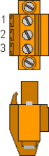 |  | 1 | | Positive Power |
| 2 | EARTH | Earth-PE (signals) | ||
| 3 | 0V power supply | |||
2.1.2 Connectivity
-
PROG PORT → Serial with standard TTL logic for programming.
-
USER PORT → Multistandard serial (RS232, RS422, RS485).
-
RS485 AUX PORT → Multistandard serial (RS232, RS422, RS485).
-
ETHERNET PORT → RJ45 connector
-
CAN PORT → Canbus type “fieldbus”.
2.1.2.1 ETHERNET port
| ETHERNET PORT | Descrizione |
|---|---|
 | Connettore RJ45. LED: * LINK: led verde = cavo collegato (il led acceso indica che il cavo è connesso ad entrambi i capi) * DATA: led giallo = scambio dati (il led lampeggiante indica lo scambio dati tra i dispositivi collegati) |
2.1.2.2 PROG PORT and USER PORT baud-rate selector
SET CAN TRANSMISSION SPEED 500 KB/S
| SW 1 | Dip | DIP setting | Function | |||
|---|---|---|---|---|---|---|
 | 1 | OFF | Baud rate 57600 | Transmission speed selection PROG PORT | ||
| ON | Baud rate 115200 | |||||
| 2 | OFF | Baud rate 57600 | Baud rate selection USER PORT | |||
| ON | Baud rate 115200 | |||||
| 3 | OFF | Can also be used by SERCOM and MODBUS | devices Operating mode selection PROG PORT | |||
| ON | Not usable by SERCOM and MODBUS devices | |||||
| 4 | OFF | ON | OFF | ON | CANbus baud rate (CanOpen) | |
| 5 | OFF | OFF | ON | ON | ||
| Baud rate 125KB/S | Baud rate 250KB/S | Baud rate 500KB/S | Baud rate 1MB/S |
|||
| 6 | OFF | MMC/SD | External media device selection in system functions | |||
| ON | USB | |||||
| 7 | Reserved for internal use. Leave OFF | |||||
| 8 | OFF | PROG PORT normal | Select the USER PORT as PROG PORT | |||
| ON | PROG PORT on the USER PORT | connector ::: | ||||
2.1.2.3 C1-R44: CN5 - CAN PORT
| CN5 | Terminal | Symbol | Description |
|---|---|---|---|
 | 1 | 0V | Common CAN |
| 2 | CANL | CAN terminal L | |
| 3 | CAN H | CAN terminal H |
2.1.2.4 Termination resistor setting
Check CAN connection to determine the activation of the termination resistor
| Name jumper | Setting | Function | |
|---|---|---|---|
JP3 JP4 | JP3 | ARMED | CAN termination activated |
| JP4 |
2.1.2.5 CAN cable connection example
There are two ways of connecting:
1st way:

2nd way:

2.1.3 Digital inputs
| S = Status | A = Action | ID |
|---|---|---|
| NO = Normally Open | I = Impulsive | ID = Software |
| NC = Normally Closed | C = Continuous |
2.1.3.1 C1-R44: CN7
| CN 7 | Pin | ID | Description | S | A | |
|---|---|---|---|---|---|---|
 | 1 | 0V | 0 Volt ( common inputs I1 ÷ I8 ) | |||
| 2 | I1 | Thermal heads | - | NC | C | |
| 3 | I2 | Bridge Fault | - | |||
| 4 | i3 | Tape Fault | - | NO | I | |
| 5 | i4 | Fault Rollers | - | |||
| 6 | i5 | Air Pressure | - | NC | C | |
| 7 | i6 | Water Pressure | - | |||
| 8 | i7 | FC Avanti Ponte | - | |||
| 9 | i8 | FC Back Bridge | - | |||
2.1.3.1.1 Connection example

2.1.3.2 C1-R44: CN6
| CN 6 | Pin | ID | Description | S | A | |
|---|---|---|---|---|---|---|
| | 1 | 0V | 0 Volt ( common inputs I9 ÷ I16 ) | |||
| 2 | i9 | Bridge zero sensor | - | NO | I | |
| 3 | I10 | Slab presence sensor | End of roller conveyors | |||
| 4 | I11 | Tape Start | ||||
| 5 | I12 | Worn Abrasive Sensor | - | |||
| 6 | i13 | Emergency | - | NC | C | |
| 7 | I14 | Pressure lubrication circuit feedback | ||||
| 8 | I15 | n.u. | Free | |||
| 9 | I16 | n.u. | Free | |||
2.1.3.2.1 Connection example

2.1.3.3 C1-R44: CN18
Duplication of IQ023 inputs if necessary
| CN 18 | Pin | ID | Description | S | A | |
|---|---|---|---|---|---|---|
| | 1 | 0V | 0 Volt ( common inputs I9 ÷ I16 ) | |||
| 2 | n.u | n.u | ||||
| 3 | i18 | Jog Bridge | Next | NO | I | |
| 4 | I19 | Back | ||||
| 5 | I20 | START | ||||
| 6 | I21 | STOP | ||||
| 7 | I22 | Abrasive Change | ||||
| 8 | I23 | MAN/AUTO | ||||
| 9 | I24 | STAND-BY | ||||
2.1.4 Digital outputs
| S = State | ID |
|---|---|
| OFF = Off | ID = Software |
| ON = On |
2.1.4.1 C1-R44: CN9 (Out +24 Volt, 500mA)
| CN 9 | Pin | ID | Description | S | |
|---|---|---|---|---|---|
 | 1 | V+ | + 24 Volt (common outputs 01 ÷ 04) | ||
| 2 | O1 | ON/OFF bridge | - | OFF | |
| 3 | O2 | Tape ON/OFF | - | ||
| 4 | O3 | ON/OFF roller conveyors | - | ||
| 5 | O4 | Up / Down Brush | - | ||
| 6 | V+ | +24 Volt (common outputs 05 ÷ 08 ) | |||
| 7 | O5 | ON/OFF previous machine | - | OFF | |
| 8 | O6 | Lubrication (optional) | - | ||
| 9 | O7 | Tape Stop | - | ||
| 10 | O8 | Alarm Status | - | ON | |
| 11 | 0V | 0 Volt (common outputs 01 ÷ 08) | |||
2.1.4.1.1 Connection example

Duplication of outputs (to facilitate wiring)
Some outputs of the RMC-3M B01 DD module are duplicated on C1-R44-FF30:
2.1.4.2 C1-R44: CN8 (Out +24 Volt, 500mA)
| CN 8 | Pin | ID | Description | Head | S |
|---|---|---|---|---|---|
| | 1 | V+ | +24 Volt (common outputs O25÷O34) | ||
| 2 | O17 | AUTO LAMP ON | OFF | ||
| 3 | O18 | ALARM LAMP | |||
| 4 | O25 | ON/OFF | 1 | ||
| 5 | O28 | 2 | |||
| 6 | V+ | +24 Volt (common outputs O37÷O46) | |||
| 7 | O31 | ON/OFF | 3 | OFF | |
| 8 | O34 | 4 | |||
| 9 | O37 | 5 | |||
| 10 | O40 | 6 | |||
| 11 | 0V | 0 Volt (common outputs O25÷O46) |
2.1.4.3 C1-R44: CN 25 (Out +24 Volt, 500 mA)
Engine starter duplication
| CN 25 | Pin | ID | Description | Head | S |
|---|---|---|---|---|---|
| | 1 | V+ | +24 Volt (common outputs O49÷O58) | ||
| 2 | O43 | ON/OFF | 7 | OFF | |
| 3 | O46 | 8 | |||
| 4 | O49 | 9 | |||
| 5 | O52 | 10 | |||
| 6 | V+ | +24 Volt (common outputs O61÷O70) | |||
| 7 | O55 | ON/OFF | 11 | OFF | |
| 8 | O58 | 12 | |||
| 9 | O61 | 13 | |||
| 10 | O64 | 14 | |||
| 11 | 0V | 0 Volt (common outputs O49÷O70) |