Indice
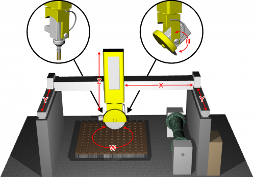
P1K31FR30-001 - 3 axis bridge saw: Connection and setup
1. Information
1.1 Release
| |
|||
| Document | P1K31FR30-001 | ||
|---|---|---|---|
| Description | Connection and setup | ||
| Drawn up | |||
| Approved | Draft | ||
| Link: | http://www.qem.eu/doku/doku.php/en/strumenti/qmoveplus/j1k31/mdu_p1k31fr30-001/connessioni_e_setup | ||
| Languages | English | ||
| Release | Description | Notes | Date |
| 01 | New Manual | 22/01/15 | |
All rights reserved on this manual. No part of this document can be copied or reproduced in any form without prior written authorisation. QEM does not insure or guarantee its contents and explicitly declines all liability related to the guarantee of its suitability for any purpose. The information in this document can be changed without notice. QEM shall not be held liable for any error or omission in this document. QEM® is a registered trademark.Microsoft® and MS-DOS® are registered trademarks and Windows® is a trademark of Microsoft Corporation.
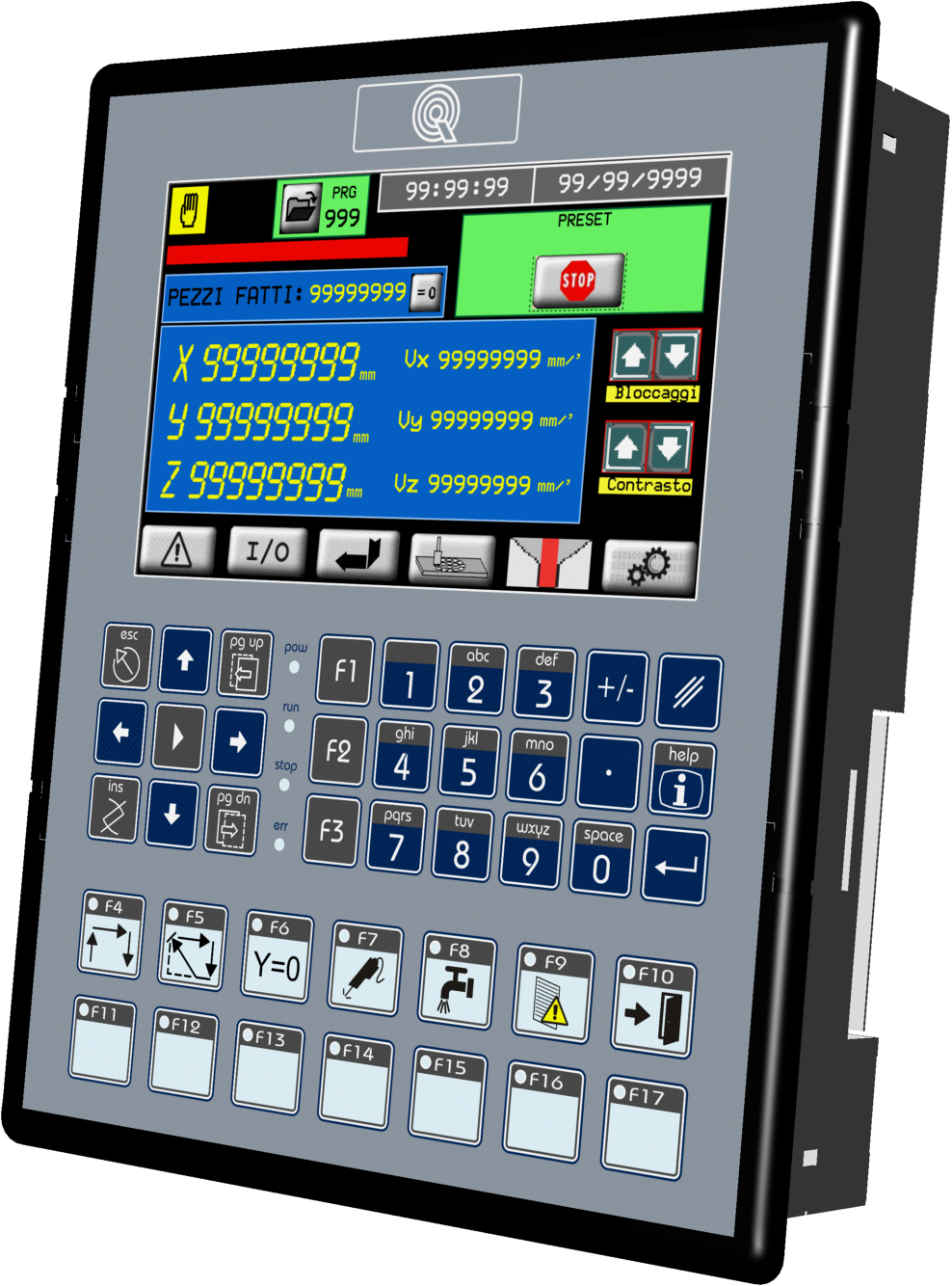
2. Hardware

3. I/O Resources
Digital Inputs (n. 32)
-
NO = Normally Opened
-
NC = Normally Closed
-
PR = Programmable
-
I = Impulsive
-
C = Continuous
| NAME | DESCRIPTION | LOGIC | TERMINAL | HARDWARE | ||
| I 1 | JOG X + |  | CN11.4 | J1K31-FR30 | ||
| I 2 | JOG X - | CN11.5 | ||||
| I 3 | JOG Y + | CN11.6 | ||||
| I 4 | JOG Y - | CN11.7 | ||||
| I 5 | JOG Z + | CN11.8 | ||||
| I 6 | JOG Z - | CN11.9 | ||||
| I 7 | Start work cycle | CN11.10 | ||||
| I 8 | Stop work cycle | CN11.11 | ||||
| I 9 | Enable manual mode | | CN12.4 | J1K31-FR30 | ||
| I 10 | Enable automatic mode | CN12.5 | ||||
| I 11 | Clear work and all axes | CN12.6 | ||||
| I 12 | Fast JOG | CN12.7 | ||||
| I 13 | Water pressure OK | CN12.8 | ||||
| I 14 | Power system OK | CN12.9 | ||||
| I 15 | Not used | CN12.10 | ||||
| I 16 | Rotary table down | CN12.11 | ||||
| I 17 | Drives OK | | CN13.4 | J1K31-FR30 | ||
| I 18 | Enclosure protection OK | CN13.5 | ||||
| I 19 | X limit switch | CN13.6 | ||||
| I 20 | Y limit switch | CN13.7 | ||||
| I 21 | Z limit switch | CN13.8 | ||||
| I 22 | W unlock position 1 ok | CN13.9 | ||||
| I 23 | W unlock position 2 ok | CN13.10 | ||||
| I 24 | Y parking switch | CN13.11 | ||||
| I 25 | Horizontal disk | CN13.4 | ||||
| I 26 | Vertical disk | | CN14.5 | J1K31-FR30 | ||
| I 27 | X Homing Switch | CN14.6 | ||||
| I 28 | Y Homing Switch | CN14.7 | ||||
| I 29 | Z Homing Switch | CN14.8 | ||||
| I 30 | W Homing Switch | CN14.9 | ||||
| I 31 | H Homing Switch | CN14.10 | ||||
| I 32 | Spindle speed ok | CN14.11 | ||||

| CN11 | Terminal | Symbol | Description | Address | |
|---|---|---|---|---|---|
 | 1 | I01(PNP) | PNP type fast input I01 | External terminal configuration1) | FREQ12) |
| 2 | I01(NPN) | PNP type fast input I01 | |||
3.0.0.1 Fast digitali inputs (n. 4)
| NAME | DESCRIPTION | LOGIC | TERMINAL | HARDWARE | ||
| I33 | Lathe one revolution sensor | CN11.1 | J1K31-FR30 | |||
| I34 | Mill inverter on | CN12.1 | ||||
| I35 | Disk inverter on | CN13.1 | ||||
| I36 | Inverter ok | CN14.1 | ||||
3.0.0.2 Digital outputs (n. 32)
| NAME | DESCRIPTION | LOGIC | TERMINAL | HARDWARE | ||
| | Output supply in (12∼28Vdc) |  | CN7.1 | J1K31-FR30 | ||
| O1 | Automatic cycle running | CN7.2 | ||||
| O2 | Not used | CN7.3 | ||||
| O3 | Alarm sound | CN7.5 | ||||
| O4 | Rotary table up | CN7.6 | ||||
| O5 | Rotary table down | CN7.8 | ||||
| O6 | Not used | CN7.9 | ||||
| O7 | X enable | CN7.10 | ||||
| O8 | Laser 2 | CN7.11 | ||||
| O9 | Y enable | CN8.2 | ||||
| O10 | Y brake | CN8.3 | ||||
| O11 | Z enable | CN8.5 | ||||
| O12 | Z brake | CN8.6 | ||||
| O13 | W enable | CN8.8 | ||||
| O14 | W enable reference | CN8.9 | ||||
| O15 | W brake | CN8.10 | ||||
| O16 | H enable | CN8.11 | ||||
| O17 | H enable reference | CN9.2 | ||||
| O18 | H brake | CN9.3 | ||||
| O19 | Water valve | CN9.5 | ||||
| O20 | Laser 1 | CN9.6 | ||||
| O21 | Reset drives | CN9.8 | ||||
| O22 | Not used | CN9.9 | ||||
| O23 | End of automatic work | CN9.10 | ||||
| O24 | Machine OK | CN9.11 | ||||
| O25 | Mill inverter enable | CN10.2 | ||||
| O26 | Disk inverter enable | CN10.3 | ||||
| O27 | Open enclosure protection | CN10.5 | ||||
| O28 | Not used | CN10.6 | ||||
| O29 | W lock position 1 ON | CN10.8 | ||||
| O30 | W lock position 2 ON | CN10.9 | ||||
| O31 | H lock position 1 ON | CN10.10 | ||||
| O32 | H lock position 2 ON | CN10.11 | ||||
Two-way encoder count inputs (n° 8)
| NAME | DESCRIPTION | LOGIC | TERMINAL | HARDWARE | ||
| CNT01 – PHA | X position | 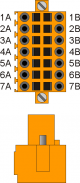 | CN15.2B | J1K31-FR30 | ||
| CNT01 – PHB | CN15.3B | |||||
| CNT02 – PHA | Y position | CN16 | J1K31-FR30 | |||
| CNT02 – PHB | CN16 | |||||
| CNT03 – PHA | Z position | CN17 | J1K31-FR30 | |||
| CNT03 – PHB | CN17 | |||||
| CNT04 – PHA | W position | CN18 | J1K31-FR30 | |||
| CNT04 – PHB | CN18 | |||||
| CNT05 – PHA | H position | CN19 | J1K31-FR30 | |||
| CNT05 – PHB | CN19 | |||||
| CNT06 – PHA | Digital potentiometer work speed | CN20 | J1K31-FR30 | |||
| CNT06 – PHB | CN20 | |||||
| CNT07 (*) | Not used | CN21 | J1K31-FR30 | |||
| CNT08 (*) | Not used | CN22 | J1K31-FR30 | |||
| (*) Not available in FR hardware version | ||||||
| CN13 | Morsetto | Simbolo | Descrizione | Indirizzo | ||
|---|---|---|---|---|---|---|
| | 1A | Internal bridge 1A -1B | ||||
| 2A | PHA1 | Fase A conteggio 1 | PNP Push-Pull1) | 3.INP25 | 3.CNT01 | |
| 3A | PHB1 | Fase B conteggio 1 | 3.INP26 | |||
| 4A | Z1 | Z conteggio 1 | 1.INT01 | |||
| 5A | 0V | Comune degli ingressi di conteggio | ||||
| 6A | 0V | |||||
| 7A | 0V | |||||
| 1B | Internal bridge 1A -1B | |||||
| 2B | PHA1+ | + PHA conteggio 1 | Line Driver | 3.INP25 | 3.CNT01 | |
| 3B | PHB1+ | + PHB conteggio 1 | 3.INP26 | |||
| 4B | Z1+ | + Z conteggio 1 | 1.INT01 | |||
| 5B | PHA1- | - PHA conteggio 1 | ||||
| 6B | PHB1- | - PHB conteggio 1 | ||||
| 7B | Z1- | - Z conteggio 1 | ||||
1)
Configurazione conteggio di tipo PNP/Push-Pull:
Morsetto 5B: collegare al morsetto 5A
Morsetto 6B: collegare al morsetto 6A
Morsetto 7B: collegare al morsetto 7A
Morsetto 5B: collegare al morsetto 5A
Morsetto 6B: collegare al morsetto 6A
Morsetto 7B: collegare al morsetto 7A
Analog inputs (n. 4)
| NAME | DESCRIPTION | LOGIC | TERMINAL | HARDWARE | ||
| IA1 | X speed potentiometer | 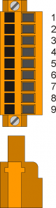 | CN28.2 | J1K31-FR30 | ||
| IA2 | X backward speed potentiometer | CN28.6 | J1K31-FR30 | |||
| IA3 | Spindle current reading | CN29.2 | J1K31-FR30 | |||
| IA4 | Spindle rpm reading | CN29.6 | J1K31-FR30 | |||
| 1 | GAI | Comune ingressi analogici | |
| 2 | IA1 | Ingresso analogico 1 | 3.AI01 |
| 3 | SEL1V | Selettore ingresso analogico 1 voltmetrico 0÷10V1) | |
| 4 | SEL1C | Selettore ingresso analogico 1 amperometrico 0÷20mA2) | |
| 5 | GAI | Comune ingressi analogici | |
| 6 | IA2 | Ingresso analogico 2 | 3.AI02 |
| 7 | SEL2V | Selettore ingresso analogico 2 voltmetrico 0÷10V3) | |
| 8 | SEL2C | Selettore ingresso analogico 2 amperometrico 4) | |
| 9 | VREF | Tensione di riferimento |
Analog outputs (n. 8)
| NAME | DESCRIPTION | LOGIC | TERMINAL | HARDWARE | ||
| GAO | Common for analog outputs | CN26.1 | ||||
| AO1 | X Speed +/-10V command | 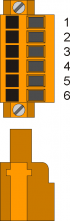 | CN26.2 | J1K31-FR30 | ||
| AO2 | Y Speed +/-10V command | CN26.3 | ||||
| AO3 | Z Speed +/-10V command | CN26.5 | ||||
| AO4 | W Speed +/-10V command | CN26.6 | ||||
| AO5 | H Speed +/-10V command | CN27 | ||||
| AO6 | Spindle rotation speed set | CN27 | ||||
| AO7 (*) | Not used | CN27 | ||||
| AO8 (*) | Not used | CN27 | ||||
| (*) Not available in FR hardware version | ||||||