Inhaltsverzeichnis
P1K31FR30-001 - 3 axis bridge saw: User Manual
| Document | P1K31FR30-001 | ||
|---|---|---|---|
| Description | User manual | ||
| Drawn up | Riccardo Furlato | ||
| Approved | Draft | ||
| Link: | http://www.qem.eu/doku/doku.php/en/strumenti/qmoveplus/j1k31/mdu_p1k31fr30-001/funzionamento | ||
| Languages | English | ||
| Release | Description | Notes | Date |
| 01 | New Manual | 26/05/14 | |
Inhaltsverzeichnis
All rights reserved on this manual. No part of this document can be copied or reproduced in any form without prior written authorisation. QEM does not insure or guarantee its contents and explicitly declines all liability related to the guarantee of its suitability for any purpose. The information in this document can be changed without notice. QEM shall not be held liable for any error or omission in this document. QEM® is a registered trademark.Microsoft® and MS-DOS® are registered trademarks and Windows® is a trademark of Microsoft Corporation.
1. Hardware J1-K31-FR30


2. General Characteristics
Description
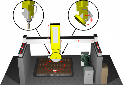
The P1K31FR30 - 001 software can be installed on the Qmove+ J1-K31-FR30, J1-P31, J1-P51, J1P71 hardware and is designed to control a bridge saw with 3 to 5 axes, for marble and granite. The salient features of the P1K31FR30 - 001 are described below.
Axes
-
Axes X, Y, Z controlled by PID on space (brushless motors with servo drives and brushless motors).
-
Axis W for the table rotation is manually controlled, with the operator entering the position on the controller
-
Axis H for the disk inclination is manually controlled, with the operator entering the angle on the controller
Optional
-
Axis W for the table rotation, with positioning accounting for inertia (asynchronous motor and V/F inverter) without interpolation.
-
Axis H for the disk inclination, with positioning accounting for inertia (asynchronous motor and V/F inverter) without interpolation.
Work Processes
-
Semiautomatic functions for positioning the axes and for single cuts.
-
Multiple cuts for block and slab cutting, with table rotation (W) for tile cutting.
-
Straight profiling with horizontal or vertical disk.
-
Step cutting with inclined disk (on machines that have disk inclination).
-
Straight profile finishing, using the face of the disk (interpolation of YZ).
Drawing
-
Profile programming by a miniCAD, embedded on the controller.
-
Import of profiles, saved on DXF file, by the “Profile Importer” conversion software (optional).
Work modes
-
Repeat the programmed shape.
-
Set the precision of the finishing.
-
Modify the speed of disk motion during the work cycle.
-
Compensation of the disk thickness and the disk diameter
Accessory functions, messages and alarms
-
Select the language
-
View the profile and the disk position, during the work cycle.
-
Diagnostics of the inputs and the outputs.
-
Backup and restore of the data on non volativle memory (FLASH EPROM).
-
Messagges for active faults, to assist troubleshooting.
-
Help Messagges.
-
Modbus interface for reading the absorbed current of the disk.
Optional Features (some not documented in this manual)
-
Profiles made with rotating table (similar to a vertical lathe).
-
Profiling with horizontal disk or vertical disk (XZ or XY interpolation).
-
Copying by photocell from a cardboard shape or black drawing on a whiteboard.
-
ISO manager with G code interpreter
Modbus Interface
-
The USER serial port can create a MODBUS RTU (RS485) network, for reading the disk rpm.
-
Serial port connection for a magnetic rule, for reading the absolute position of the axis.
2.1 Typical work results

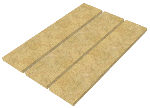 Multiple cuts | 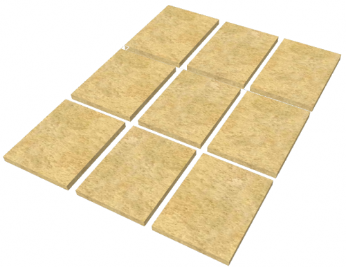 Tile cuts | 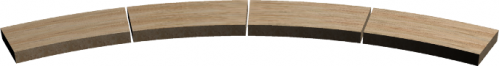 Arc tiles |
 Profile roughing |  Profile finishing | 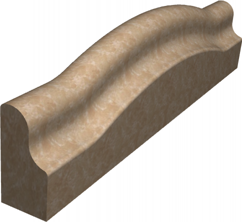 Curved profile roughing |
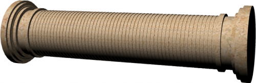 Column roughing | 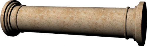 Column finishing |  Horizontal profile roughing |
 Circular Top roughing |  Spiral stairs |  G-code relief |
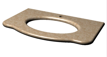 Top milling | 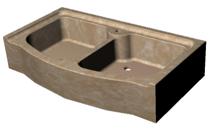 Sinks & drains | 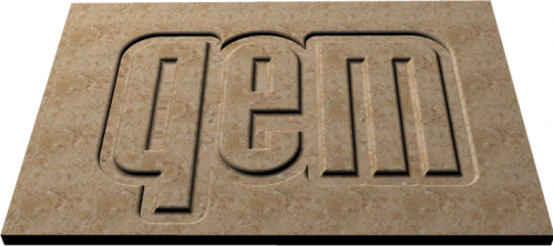 G-code texting |
3. Keys and Symbols
3.1 Tasti
| Press to confirm | |
| Select multile parameters | |
 | Previous screen |
 | Next screen |
 | General Setup (protected by password) |
| Apri da MMC | |
| Salva |
Campi numerici gialli …possono essere impostati
3.2 Function Keys
| Tasto | Icona | Funzione | Tasto | Icona | Funzione |
|---|---|---|---|---|---|
| F4 | | SBLOCCA BARRIERE | F5 | - | - |
| F6 | | LASER Y. | F7 | | LASER X. ★ Laser ON/OFF. ★ Con asse Y = ON, laser = ON. |
| F8 | | ACQUA. ★ ON/OFF elettrovalvola acqua. ★ In ciclo automatico elettrovalvola = ON | F9 | | ALLARMI. Allarmi attivi. |
| F10 | | USCITA. Esce dalla pagina. | F11 | | SEMIAUTOMATICO. Abilita un solo posizionamento di Jog |
| F12 | | ALZA BANCO | F13 | | ABBASSA BANCO |
| F14 | | ROTAZIONE BANCO ANTIORARIA | F15 | | ROTAZIONE BANCO ORARIA |
| F16 | | AVVIO DISCO | F17 | | ABILITAZIONE AVVIO FRESA. |
I tasti di Start e Stop lavorazione …li faremo esterni come si conviene con un macchina seria…per il momento li metteremo in parallelo a questi
Dobbiamo prevedere la selezione dei Jog .. che devono esserci sia nella apparecchiatura …ma sia devono anche esserci su una pulsantiera remota
L'idea è quella di renderli disponibili sulla tastiera in basso a sinistra …collocando i tasti in modo che mi sembrano più utilizzabili
ovvero Y Z X W
nota : la priorità sarà data ai comandi da pulsantiera remota
…una selezione di abilitazione cancellerà l'eventuale selezione fatta agendo su questi tasti
Per poter avere questi tasti …andremo ad utilizzare i tasti di azzeramento degli assi
…che ritengo pericolosi poterli attivare ( come sono ora ) senza entrare in un pagina specifica
★ Mancano poi i pulsanti di sollevamento banco ( il pulsante di solevamento sarà poi in serie al fine corsa banco in posizione di ribaltamento
3.3 Function leds
| Led | Icona | Funzione | Led | Icona | Funzione |
|---|---|---|---|---|---|
| F4 | | Barriere | F5 | non usato | non usato. |
| F6 | | Laser Y ON/OFF | F7 | | Laser X ON/OFF |
| F8 | | EV acqua ON/OFF | F9 | | Allarme = ON |
| F10 | | Esci | F11 | | Semiautomatico = ON |
| F12 | | Alza banco | F13 | | Abbassa banco |
| F14 | | Rotazione antioraria banco | F15 | | Rotazione oraria banco |
| F16 | | Disco ON/OFF | F17 | | Fresa ON/OFF |
3.4 Symbols
| Symbol | Description |
|---|---|
| | Manual |
| | Emergency |
| | Automatic |
| | Function mode |
| | Not initialized |
| | Locked/Unlocked setup |
3.5 Up-bar
| Symbol | Description |
|---|---|
 | Barra alta (sfondo grigio)
|
4. STARTUP PAGE
![]()
La pagina resta attiva con il messaggio „WAITING FOR POWER SYSTEM“ finché non viene tolta l'emergenza.
Per proseguire premere 
5. HOMING (PRESET) PAGE
  | |
||
 |  | ||
6. FUNCTION STARTUP
6.1 Pagine installatore - Accesso ai parametri di default
| | |
|||
 |  |
|||
 PASSWORD:462  |  |
|||
| G DEF - X DEF Y DEF - Z DEF W DEF - H DEF |  |
|||
6.2 Pagine installatore - Accesso alla diagnostica
| | |
||||
| | |
||||
| PASSWORD:462 | |
||||
 | I/O |  |
|||
| INPUTS  |  |
||||
| OUTPUTS |  |
||||
| COUNTERS |  |
||||
| ANALOG OUTS |  |
||||
6.3 Pagine installatore - Accesso ai parametri
| | |
|||
| | |
|||
| PASSWORD:462 | |
|||
| GEN - X SETUP Y SETUP - Z SETUP W SETUP - H SETUP |  |
|||
6.4 Pagine installatore - Taratura assi
| | |
||||
| | |
||||
| PASSWORD:462 | |
||||
| X CAL - Y CAL Z CAL - W CAL H CAL |  |
||||
| RESOLUTION |  |
||||
| P.I.D. |  |
||||
| LINEARIZATION |  |
||||
6.5 Pagine operatore - Accesso ai programmi
| | |
|
 |  |
|
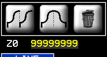
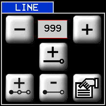
6.6 Pagine operatore - Cancella programmi
| | |
|
| | |
|
| |  |
|
6.7 Pagine operatore - Esecuzione programma
| | |
|||
| | |
|||
| RUN  |  |
|||
| |  |
|||
| |  |
|||
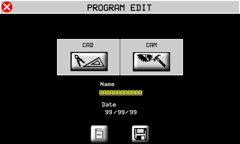
6.8 Pagine operatore - Nuovo programma lavorazione profili
| | |
||||
| | |
||||
 |  |
||||
  |  |
||||
 |  Vedi capitolo CAD |
||||
 |    Vedi capitolo PROFILING PARAMETERS |
||||
| |  |
||||
| |  |
||||
6.9 Pagine operatore - Nuovo programma lavorazione fresa
| | |
||||
| | |
||||
| | |
||||
 |  |
||||
| |  Vedi capitolo CAD |
||||
| |  Vedi capitolo CAM |
||||
| | |
||||
| | |
||||
6.10 Pagine operatore - Nuovo programma taglio poligoni
| | |
||||
| | |
||||
| | |
||||
 | |
||||
| | Vedi capitolo CAD |
||||
| |  Vedi capitolo CAM |
||||
| | |
||||
| | |
||||
6.11 Pagine operatore - Apri programma
| | |
||||
| | |
||||
 | |
||||
| | |
||||
| | Vedi capitolo CAD |
||||
| | Vedi capitolo CAM |
||||
| | |
||||
| | |
||||
6.12 Pagine operatore - Manuale/Automatico
| | |
||
 |  |
||
 |  Vedi capitolo Manuale/Automatico |
||
 |  Vedi capitolo Manuale/Automatico |
||
 |  Vedi capitolo Manuale/Automatico |
||
 |  Vedi capitolo Manuale/Automatico |
||
 |  Vedi capitolo Manuale/Automatico |
||
 |  Vedi capitolo Manuale/Automatico |
||
6.13 Pagine operatore - Tagli multipli
| | |
||
 |  |
||
| |  |
||
| | |
||
| |  |
||
6.14 Pagine operatore - Tagli inclinati
| | |
||
 |  |
||
| | |
||
| | |
||
| |  |
||
6.15 Pagine operatore - Esecuzione ISO code
| | | ||
 |  |
||
7. SETUP
Toccare il valore del parametro e modificare con il tastierino numerico.
Per confermare premere il tasto 
7.1 Caricamento dei parametri di default
| G DEF - X DEF Y DEF - Z DEF W DEF - H DEF | |
|
| YES | Per caricare i dati di default | |
| NO | Per annullare | |
7.2 Parametri generici
| GEN  | |
 previous page next page save data if changed previous page next page save data if changed |
-
PG-XX = Parameters Generic, XX = number
-
P.ter = Parameters
-
U.M. = Unit Measure
-
Def. = Default
| P.ter | U.M. | Def. | Range | Description |
|---|---|---|---|---|
| PG-01 : DECIMAL POINT X/Y/Z | - | 1 | 0 - 2 | Number of decimal point for X, Y and Z axis position visualization. For inches position the visualization will be „DECIMAL POINT + 1“. |
| PG-02 : DECIMAL POINT W | - | 2 | 0 - 2 | Number of decimal point for W axis position visualization. |
| PG-03 : DECIMAL POINT H | - | 2 | 0 - 2 | Number of decimal point for H axis position visualization. |
| PG-04 : MAX RPM DISK | rpm | 2480 | 0 - 3000 | Maximum value of disk rpm. |
| PG-05 : LASER TIMER | s | 30 | 0 - 9999 | If this value is greather than zero the laser active automatic when Y axis moving. When axis stops after this time, laser powers off automatically. If time is zero laser could be actived only by F7 button. |
| PG-06 : WATER CONTROL TIMER | s | 5 | 0 - 9999 | In case of water fault, relative alarm is shown after this time. |
| PG-07 : DISABLE WATER CONTROL | - | 0 | 0 - 1 | 0: water control enabled; 1: water control disabled. |
| PG-08 : BUZZER HMI | - | 0 | 0 - 1 | 0: buzzer enabled; 1: buzzer disabled. |
| PG-09 : ALARM SOUND TIMER | s | 10 | 0 - 999 | Time of Alarm sound output activation when machine goes in alarm state. |
| PG-10 : UNIT MEASURE | - | 0 | 0 - 1 | 0: mm 1: inch In setup area all parameters will be shown in mm. |
| PG-11 : LANGUAGE | - | 1 | 1 - 2 | 1: ENGLISH 2: ITALIAN |
| PG-12 : HOMING MODE | - | 1 | 0 - 3 | 0:Homing necessary to unlock all other operations; 1:Homing not necessary, all functions are unlocked; 2:Homing necessary for automatic cycle, only manual movements free; 3:Homing necessary to unlock all other operations. Homing procedure starts automatically without pressing any button. |
| PG-13 : free | - | 0 | free | |
| PG-14 : MIN VALUE ANAL. INPUT | bit | 5 | 0 - 1000 | Under this value, all analog inputs are forced to zero. |
| PG-15 : INTERPOLATION SPEED OVERRIDE | - | 0 | 0 - 1 | 0: override applied to calculated speed 1: override applied to set speed |
| PG-16 : CORNER TYPE | - | 0 | 0 - 1 | 0: corner with smoothed center 1: not implemented |
| PG-17 : CORNER ERROR | mm | 0.5 | 0 - 999.9 | Distance error from corner begin and center of the corner. (x) |
| PG-18 : RAPID SPEED | mm/min | 1000 | 0 - 9999 | Feedrate of straight traverse and default value for other blocks. |
| PG-19 : MAX CURRENT | A | 100.0 | 0 - 100.0 | Maximum value of analogic input for spindle current. |
| PG-20 : TIME FOR SPINDLE SPEED OK | s | 0 | 0 - 99.999 | 0: machine waits input I 15 for spindle speed ok >0: machine waits only time |
| PG-21 : MAX RPM MILL | rpm | 3000 | 0 - 3000 | Maximum value of mill rpm. |
| PG-22 : HOMING COMBINATION | - | 0 | 0 - 1 | 0: single axis homing; 1: after Z axis homing, the others are contemporary. |
(x) parameter decimal point depend on PG-01 value.
7.3 X, Y, Z axis setup
| X SETUP  Y SETUP  Z SETUP  | |
| previous page next page save data if changed |
-
PX-XX = Parameters, X = axe, XX = number
-
P.ter = Parameters
-
U.M. = Unit Measure
-
Def. = Default
| P.ter | U.M. | Def. | Range | Description |
|---|---|---|---|---|
| PX-01 : MEASURE | mm | 0.1 | 0 - 99999.9 | Distance, in unit measure, of the axis shift to obtain the pulses set in parameter PULSE (x). |
| PX-02 : PULSE | - | 1 | 0 - 999999 | Pulses of the encoder corresponding to the distance set in parameter MEASURE. Measure/Pulse is axis resolution. It has to be between 1 and 0.000935. |
| PX-03 : TOLERANCE | mm | 0.50 | 0 - 99.99 | Interval around target quota. If axis stops in this interval , the positioning is correct.(xx) |
| PX-04 : ENABLE TIME | s | 0.200 | 0 - 9.999 | Enable time before axis starts moving. |
| PX-05 : DISABLE TIME | s | 0.200 | 0 - 9.999 | Disable time after axis stops. |
| PX-06 : ENABLE AXIS OUTPUT | - | 1 | 0 - 1 | Enable axis output function. 0: output on before axis movement and off after axis stop, according to the timer set in PX-04 and PX-05. 1: output on at switching on and off when machine is in alarm state. |
| PX-07 : JOG FUNCTION | - | 1 | 0 - 1 | Jog function type. 0: during jog, axis control is open loop. 1: during jog, axis control is closed loop. |
| PX-08 : MAXIMUM QUOTA | mm | 99999.9 | -99999.9 - 99999.9 | Maximum quota for the axis. Software limit switch.(x) |
| PX-09 : MINIMUM QUOTA | mm | -99999.9 | -99999.9 - 99999.9 | Minimum quota for the axis. Software limit switch.(x) |
| PX-10 : HOMING OFFSET | mm | 0 | -99999.9 - 99999.9 | Set position at the end of homing procedure.(x) |
| PX-11 : HOMING TYPE | - | 0 | 0 - 3 | 0: Axis searches the homing sensor, inverts movement and set PX-10 quota. 1: Axis searches the homing sensor, inverts movement and set PX-10 quota on encoder zero signal. 2: Axis homing without movement. Set PX-10 quota on homing sensor signal. 3: homing disabled. |
| PX-12 : HOMING DIRECTION | - | 0 | 0 - 1 | 0:forward; 1:backward. |
| PX-13 : HOMING FAST SPEED | mm/min | 10 | 0 - 9999999 | Homing sensor searching speed. |
| PX-14 : HOMING SLOW SPEED | mm/min | 10 | 0 - 9999999 | Axis speed after movement inversion in homing. |
| PX-15 : HOMING SEQUENCE ENABLE | - | 1 | 0 - 1 | 0: Axis not included in automatic homing sequence. 1: Axis included in automatic homing sequence. |
| PX-16 : ACCELERATION TIME IN AUTOMATIC | s | 1.00 | 0 - 9.99 | Time from 0 to axis maximum speed. |
| PX-17 : DECELERATION TIME IN AUTOMATIC | s | 1.00 | 0 - 9.99 | Time from axis maximum speed to 0. |
| PX-18 : ACCELERATION TIME IN MANUAL | s | 1.00 | 0 - 9.99 | Time from 0 to axis maximum speed. |
| PX-19 : DECELERATION TIME IN MANUAL | s | 1.00 | 0 - 9.99 | Time from axis maximum speed to 0. |
| PX-20 : WAIT TOLERANCE TIMER | s | 0.50 | 0 - 99.99 | Time between axis stop and tolerance control. |
| PX-21 : AUTOMATIC SPEED FORWARD | mm/min | 10 | 0 - 9999999 | Axis forward speed during automatic cycle. |
| PX-22 : AUTOMATIC SPEED BACKWARD | mm/min | 10 | 0 - 9999999 | Axis backward speed during automatic cycle. |
| PX-23 : MANUAL FAST SPEED | mm/min | 10 | 0 - 9999999 | Axis fast speed during manual jog movement. |
| PX-24 : MANUAL SLOW SPEED | mm/min | 10 | 0 - 9999999 | Axis slow speed during manual jog movement. |
| PX-25 : MINIMUM SHIFT | mm | 0.1 | 0 - 999.9 | Encoder fault control: minimum shift for the axis.(x) |
| PX-26 : VOLTAGE THRESHOLD | V | 1.0 | 0 - 10.0 | Encoder fault control : minimum voltage to start encoder control. |
| PX-27 : END CYCLE PARKING | - | 0 | 0 - 1 | Enable Parking position at the end of automatic cycle. 0: disabled 1: enabled |
| PX-28 : MAXIMUM SPEED | mm/min | 100 | 0 - 9999999 | Axis maximum speed with 10Vdc applied. |
| PX-29 : FEEDFORWARD | % | 100.0 | 0 - 200.0 | Feed-forward register for PID regulation. |
| PX-30 : PROPORTIONAL GAIN | - | 0 | 0 - 9.999 | Proportional gain register for PID regulation. |
| PX-31 : INTEGRAL TIME | s | 0 | 0 - 9.999 | Integral register for PID regulation. |
| PX-32 : DERIVATIVE TIME | s | 0 | 0 - 9.999 | Derivative register for PID regulation. |
| PX-33 : MAXIMUM FOLLOWING ERROR | mm | 9999.99 | 0 - 9999.99 | Maximum error between theoric and real position of the axis. (xx) |
| PX-34 : OFFSET | V | 0 | -99.9999 - 99.9999 | Analogic output offset for drive compensation. |
| PX-35 : MAXIMUM INTERPOLATION SPEED | % | 80.0 | 0 - 100.0 | Maximum interpolation speed. Percentage of maximum speed in PX-28. |
| PX-36 : HOMING SENSOR LOGIC | - | 0 | 0 - 1 | 0: Sensor NO (normally open). 1: Sensor NC (normally close). |
| PX-37 : APPROACH QUOTA | mm | 10.0 | 0 - 999.9 | If > 0 pulse positioning enable. Quota before target where pulse positioning begins.(x) |
| PX-38 : PULSE AMPLITUDE | V | 0.1 | 0 - 10.0 | Pulse amplitude in volt. |
| PX-39 : PULSE TIME | s | 0.20 | 0 - 99.99 | Time of a single pulse step ( period??). |
| PX-40 : PULSE DELAY | s | 0.20 | 0 - 99.99 | Time between two steps. |
| PX-41 : PULSE TIMEOUT | s | 0 | 0 - 99 | Pulse positioning maximum time. |
7.3.1 Parameters valid only for X axis
| P.ter | U.M. | Def. | Range | Description |
|---|---|---|---|---|
| PX-42 : TABLE CENTER COORDINATE | mm | 1000.0 | -99999.9 - 99999.9 | Axis coordinate of the rotary table.(x) |
| PX-43 : OFFSET DRILL-DISK | mm | 0.0 | -99999.9 - 99999.9 | Distance between disk center and drill center. |
| PX-44 : RAMP TYPE | - | 0 | 0 - 1 | 0: Linear ramps. 1: Epicyclic ramps. |
7.3.2 Parameters valid only for Y axis
| P.ter | U.M. | Def. | Range | Description |
|---|---|---|---|---|
| PY-42 : TABLE CENTER COORDINATE | mm | 1000.0 | -99999.9 - 99999.9 | Axis coordinate of the rotary table.(x) |
| PY-43 : TOLERANCE ALARM DISABLE | - | 0 | 0 - 1 | 0: alarm enabled 1: alarm disabled |
| PY-44 : OFFSET DRILL-DISK | mm | 100.0 | -99999.9 - 99999.9 | Distance between disk center and drill center. |
| PY-45 : RAMP TYPE | - | 0 | 0 - 1 | 0: Linear ramps. 1: Epicyclic ramps. |
7.3.3 Parameters valid only for Z axis
| P.ter | U.M. | Def. | Range | Description |
|---|---|---|---|---|
| PZ-42 : TOLERANCE ALARM DISABLE | - | 0 | 0 - 1 | 0: alarm enabled 1: alarm disabled |
| PZ-43 : RAMP TYPE | - | 0 | 0 - 1 | 0: Linear ramps. 1: Epicyclic ramps. |
(x) parameter decimal point depend on PG-01 value.
(xx) parameter decimal point depend on PG-01 value plus one.
7.4 W axis setup
| W SETUP  | |
| previous page next page save data if changed |
-
PX-XX = Parameters, X = axe, XX = number
-
P.ter = Parameters
-
U.M. = Unit Measure
-
Def. = Default
| P.ter | U.M. | Def. | Range | Description |
|---|---|---|---|---|
| PW-01 : AXIS ENABLE | - | 0 | 0 - 1 | 0: axis disabled 1: axis enabled |
| PW-02 : MEASURE | ° | 0.01 | 0 - 9999.99 | Distance, in unit measure, of the axis shift to obtain the pulses set in parameter PULSE. |
| PW-03 : PULSE | - | 1 | 0 - 999999 | Pulses of the encoder corresponding to the distance set in parameter MEASURE. Measure/Pulse is axis resolution. It has to be between 1 and 0.000935. |
| PW-04 : TOLERANCE | ° | 0.050 | 0 - 99.999 | Interval around target quota. If axis stops in this interval , the positioning is correct. |
| PW-05 : ENABLE TIME | s | 0.200 | 0 - 9.999 | Enable time before axis starts moving. |
| PW-06 : DISABLE TIME | s | 0.200 | 0 - 9.999 | Disable time after axis stops. |
| PW-07 : SPACE IN SLOW | ° | 5.00 | 0 - 99.99 | Space in slow speed. Target quota when axis speed slows down before final target. |
| PW-08 : FORWARD INERTIA | ° | 0 | 0 - 99.999 | Inertia space at the end of forward movements. |
| PW-09 : BACKWARD INERTIA | ° | 0 | 0 - 99.999 | Inertia space at the end of backward movements. |
| PW-10 : INERTIA MODE | - | 0 | 0 - 2 | At the end of positioning: 0: inertia not calculated 1: calculated if out of tolerance 2: always calculated |
| PW-11 : WAIT TOLERANCE TIMER | s | 1.000 | 0 - 9.999 | Time between axis stop and tolerance control. |
| PW-12 : BACKLASH MODE | - | 0 | 0 - 4 | 0: no backlash 1: forward backlash 2: backward backlash 3: forward backlash without speed slow down 4: backward backlash without speed slow down |
| PW-13 : OVER POSITION | ° | 0 | 0 - 999.99 | Over quota for backlash. |
| PW-14 : AUTOMATIC FAST SPEED | % | 10.0 | 0 - 100.0 | Axis fast speed during automatic cycle. |
| PW-15 : AUTOMATIC SLOW SPEED | % | 5.0 | 0 - 100.0 | Axis slow speed during automatic cycle. |
| PW-16 : MANUAL FAST SPEED | % | 10.0 | 0 - 100.0 | Axis fast speed during manual jog movement. |
| PW-17 : MANUAL SLOW SPEED | % | 5.0 | 0 - 100.0 | Axis slow speed during manual jog movement. |
| PW-18 : HOMING FAST SPEED | % | 10.0 | 0 - 100.0 | Axis speed at the start of homing. |
| PW-19 : HOMING SLOW SPEED | % | 1.0 | 0 - 100.0 | Axis speed after movement inversion in homing. |
| PW-20 : HOMING SEQUENCE ENABLE | - | 1 | 0 - 1 | 0: Axis not included in automatic homing sequence. 1: Axis included in automatic homing sequence. |
| PW-21 : HOMING OFFSET | ° | 0 | -9999.99 - 9999.99 | Set position at the end of homing procedure. |
| PW-22 : HOMING TYPE | - | 0 | 0 - 3 | 0: Axis searches the homing sensor, inverts movement and set PW-22 quota. 1: Axis searches the homing sensor, inverts movement and set PW-22 quota on encoder zero signal. 2: Axis homing without movement. Set PW-22 quota on homing sensor signal. 3: homing disabled. |
| PW-23 : HOMING DIRECTION | - | 1 | 0 - 1 | 0:forward; 1:backward. |
| PW-24 : MAXIMUM QUOTA | ° | 9999.99 | -9999.99 - 9999.99 | Maximum quota for the axis. Software limit switch. |
| PW-25 : MINIMUM QUOTA | ° | -9999.99 | -9999.99 - 9999.99 | Minimum quota for the axis. Software limit switch. |
| PW-26 : MINIMUM SHIFT | ° | 0.10 | 0 - 99.99 | Encoder fault control: minimum shift for the axis. |
| PW-27 : MINIMUM TIMER | s | 2.000 | 0 - 99.99 | Encoder fault control : sample time to check minimum shift. |
| PW-28 : BRAKE LOGIC | - | 1 | 0 - 1 | 0: Brake output N.O. 1: Brake output N.C. |
| PW-29 : BRAKE TIMER | s | 1.000 | 0 - 9.999 | Enable time before axis starts moving and after axis stop. |
| PW-30 : ACCELERATION | V/s | 20.00 | 0 - 99.99 | Acceleration value. |
| PW-31 : DECELERATION | V/s | 20.00 | 0 - 99.99 | Deceleration value. |
| PW-32 : PULSE ENABLE | - | 0 | 0 - 1 | 0: Pulse positioning disable. 1: Pulse positioning enable. |
| PW-33 : APPROACH QUOTA | ° | 0.30 | 0 - 999.99 | Quota before target where pulse positioning begins. |
| PW-34 : PULSE TIME | s | 0.100 | 0 - 9.999 | Time of a single pulse step. |
| PW-35 : PULSE DELAY | s | 0.100 | 0 - 9.999 | Time between two steps. |
| PW-36 : PULSE NUMBER | - | 40 | 0 - 9999 | Maximum number of pulse step. |
| PW-37 : PULSE AMPLITUDE | V | 0.1 | 0 - 10.0 | Pulse amplitude in volt. |
| PW-38 : ENABLE SPINE | - | 0 | 0 - 1 | 0: Conic spine insertion disable. 1: Conic spine insertion enable. |
| PW-39 : SPINE DELAY | s | 0.200 | 0 - 9.999 | Time between spine insertion and brake output. |
| PW-40 : POSITION SPINE 1 | ° | 0 | -9999.99 - 9999.99 | Position for spine n° 1. |
| PW-41 : POSITION SPINE 2 | ° | 90.00 | -9999.99 - 9999.99 | Position for spine n° 2. |
| PW-42 : ENABLE CONVERSION | - | 0 | 0 - 1 | 0: position linear conversion disable. 1: position linear conversion enable. |
| PW-43 : REAL POSIT 2 | ° | 45.00 | -9999.99 - 9999.99 | Axis real position in sector N°2. |
| PW-44 : CONV. POSIT 2 | ° | 45.00 | -9999.99 - 9999.99 | Axis converted position in sector N°2. |
| PW-45 : REAL POSIT 3 | ° | 90.00 | -9999.99 - 9999.99 | Axis real position in sector N°3. |
| PW-46 : CONV. POSIT 3 | ° | 90.00 | -9999.99 - 9999.99 | Axis converted position in sector N°3. |
| PW-47 : REAL POSIT 4 | ° | 135.00 | -9999.99 - 9999.99 | Axis real position in sector N°4. |
| PW-48 : CONV. POSIT 4 | ° | 135.00 | -9999.99 - 9999.99 | Axis converted position in sector N°4. |
| PW-49 : REAL POSIT 5 | ° | 180.00 | -9999.99 - 9999.99 | Axis real position in sector N°5. |
| PW-50 : CONV. POSIT 5 | ° | 180.00 | -9999.99 - 9999.99 | Axis converted position in sector N°5. |
| PW-51 : REAL POSIT 6 | ° | 225.00 | -9999.99 - 9999.99 | Axis real position in sector N°6. |
| PW-52 : CONV. POSIT 6 | ° | 225.00 | -9999.99 - 9999.99 | Axis converted position in sector N°6. |
| PW-53 : REAL POSIT 7 | ° | 270.00 | -9999.99 - 9999.99 | Axis real position in sector N°7. |
| PW-54 : CONV. POSIT 7 | ° | 270.00 | -9999.99 - 9999.99 | Axis converted position in sector N°7. |
| PW-55 : REAL POSIT 8 | ° | 315.00 | -9999.99 - 9999.99 | Axis real position in sector N°8. |
| PW-56 : CONV. POSIT 8 | ° | 315.00 | -9999.99 - 9999.99 | Axis converted position in sector N°8. |
7.5 H axis setup
| H SETUP  | |
| previous page next page save data if changed |
-
PX-XX = Parameters, X = axe, XX = number
-
P.ter = Parameters
-
U.M. = Unit Measure
-
Def. = Default
| P.ter | U.M. | Def. | Range | Description |
|---|---|---|---|---|
| PH-01 : INCLINATION TYPE | - | 1 | 0 - 1 | 0: axis inclination with Z axis 1: axis inclination only head |
| PH-02 : MOTOR | - | 0 | 0 - 2 | 0: axis without encoder and motor 1: axis with only encoder 2: axis with encoder and motor |
| PH-03 : empty | - | - | - | - |
| PH-04 : MEASURE | ° | 0.01 | 0 - 9999.99 | Distance, in unit measure, of the axis shift to obtain the pulses set in parameter PULSE. |
| PH-05 : PULSE | - | 1 | 0 - 999999 | Pulses of the encoder corresponding to the distance set in parameter MEASURE. Measure/Pulse is axis resolution. It has to be between 1 and 0.000935. |
| PH-06 : TOLERANCE | ° | 0.050 | 0 - 99.999 | Interval around target quota. If axis stops in this interval , the positioning is correct. |
| PH-07 : ENABLE TIME | s | 0.200 | 0 - 9.999 | Enable time before axis starts moving. |
| PH-08 : DISABLE TIME | s | 0.200 | 0 - 9.999 | Disable time after axis stops. |
| PH-09 : SPACE IN SLOW | ° | 5.00 | 0 - 99.99 | Space in slow speed. Target quota when axis speed slows down before final target. |
| PH-10 : FORWARD INERTIA | ° | 0 | 0 - 99.999 | Inertia space at the end of forward movements. |
| PH-11 : BACKWARD INERTIA | ° | 0 | 0 - 99.999 | Inertia space at the end of backward movements. |
| PH-12 : INERTIA MODE | - | 0 | 0 - 2 | At the end of positioning: 0: inertia not calculated 1: calculated if out of tolerance 2: always calculated |
| PH-13 : WAIT TOLERANCE TIMER | s | 1.000 | 0 - 9.999 | Time between axis stop and tolerance control. |
| PH-14 : BACKLASH MODE | - | 0 | 0 - 4 | 0: no backlash 1: forward backlash 2: backward backlash 3: forward backlash without speed slow down 4: backward backlash without speed slow down |
| PH-15 : OVER POSITION | ° | 0 | 0 - 999.99 | Over quota for backlash. |
| PH-16 : AUTOMATIC FAST SPEED | % | 10.0 | 0 - 100.0 | Axis fast speed during automatic cycle. |
| PH-17 : AUTOMATIC SLOW SPEED | % | 5.0 | 0 - 100.0 | Axis slow speed during automatic cycle. |
| PH-18 : MANUAL FAST SPEED | % | 10.0 | 0 - 100.0 | Axis fast speed during manual jog movement. |
| PH-19 : MANUAL SLOW SPEED | % | 5.0 | 0 - 100.0 | Axis slow speed during manual jog movement. |
| PH-20 : HOMING FAST SPEED | % | 10.0 | 0 - 100.0 | Axis speed at the start of homing. |
| PH-21 : HOMING SLOW SPEED | % | 1.0 | 0 - 100.0 | Axis speed after movement inversion in homing. |
| PH-22 : HOMING SEQUENCE ENABLE | - | 1 | 0 - 1 | 0: Axis not included in automatic homing sequence. 1: Axis included in automatic homing sequence. |
| PH-23 : HOMING OFFSET | ° | 0 | -9999.99 - 9999.99 | Set position at the end of homing procedure. |
| PH-24 : HOMING TYPE | - | 0 | 0 - 3 | 0: Axis searches the homing sensor, inverts movement and set PH-24 quota. 1: Axis searches the homing sensor, inverts movement and set PH-24 quota on encoder zero signal. 2: Axis homing without movement. Set PH-24 quota on homing sensor signal. 3: homing disabled. |
| PH-25 : HOMING DIRECTION | - | 1 | 0 - 1 | 0:forward; 1:backward. |
| PH-26 : MAXIMUM QUOTA | ° | 9999.99 | -9999.99 - 9999.99 | Maximum quota for the axis. Software limit switch. |
| PH-27 : MINIMUM QUOTA | ° | -9999.99 | -9999.99 - 9999.99 | Minimum quota for the axis. Software limit switch. |
| PH-28 : MINIMUM SHIFT | ° | 0.10 | 0 - 99.99 | Encoder fault control: minimum shift for the axis. |
| PH-29 : MINIMUM TIMER | s | 2.000 | 0 - 99.999 | Encoder fault control : sample time to check minimum shift. |
| PH-30 : BRAKE LOGIC | - | 1 | 0 - 1 | 0: Brake output N.O. 1: Brake output N.C. |
| PH-31 : BRAKE TIMER | s | 1.000 | 0 - 9.999 | Enable time before axis starts moving and after axis stop. |
| PH-32 : ACCELERATION | V/s | 20.00 | 0 - 99.99 | Acceleration value. |
| PH-33 : DECELERATION | V/s | 20.00 | 0 - 99.99 | Deceleration value. |
| PH-34 : PULSE ENABLE | - | 0 | 0 - 1 | 0: Pulse positioning disable. 1: Pulse positioning enable. |
| PH-35 : APPROACH QUOTA | ° | 0.30 | 0 - 999.99 | Quota before target where pulse positioning begins. |
| PH-36 : PULSE TIME | s | 0.100 | 0 - 9.999 | Time of a single pulse step. |
| PH-37 : PULSE DELAY | s | 0.100 | 0 - 9.999 | Time between two steps. |
| PH-38 : PULSE NUMBER | - | 40 | 0 - 9999 | Maximum number of pulse step. |
| PH-39 : PULSE AMPLITUDE | V | 0.1 | 0 - 10.0 | Pulse amplitude in volt. |
| PH-40 : ENABLE SPINE | - | 0 | 0 - 1 | 0: Conic spine insertion disable. 1: Conic spine insertion enable. |
| PH-41 : SPINE DELAY | s | 0.200 | 0 - 9.999 | Time between spine insertion and brake output. |
| PH-42 : POSITION SPINE 1 | ° | 0 | -9999.99 - 9999.99 | Position for spine n° 1. |
| PH-43 : POSITION SPINE 2 | ° | 90.00 | -9999.99 - 9999.99 | Position for spine n° 2. |
| PH-44 : ENABLE CONVERSION | - | 0 | 0 - 1 | 0: position linear conversion disable. 1: position linear conversion enable. |
| PH-45 : REAL POSIT 2 | ° | 22.50 | -9999.99 - 9999.99 | Axis real position in sector N°2. |
| PH-46 : CONV. POSIT 2 | ° | 22.50 | -9999.99 - 9999.99 | Axis converted position in sector N°2. |
| PH-47 : REAL POSIT 3 | ° | 45.00 | -9999.99 - 9999.99 | Axis real position in sector N°3. |
| PH-48 : CONV. POSIT 3 | ° | 45.00 | -9999.99 - 9999.99 | Axis converted position in sector N°3. |
| PH-49 : REAL POSIT 4 | ° | 67.50 | -9999.99 - 9999.99 | Axis real position in sector N°4. |
| PH-50 : CONV. POSIT 4 | ° | 67.50 | -9999.99 - 9999.99 | Axis converted position in sector N°4. |
| PH-51 : REAL POSIT 5 | ° | 90.00 | -9999.99 - 9999.99 | Axis real position in sector N°5. |
| PH-52 : CONV. POSIT 5 | ° | 90.00 | -9999.99 - 9999.99 | Axis converted position in sector N°5. |
| PH-53 : REAL POSIT 6 | ° | 0 | -9999.99 - 9999.99 | Axis real position in sector N°6. |
| PH-54 : CONV. POSIT 6 | ° | 0 | -9999.99 - 9999.99 | Axis converted position in sector N°6. |
| PH-55 : REAL POSIT 7 | ° | 0 | -9999.99 - 9999.99 | Axis real position in sector N°7. |
| PH-56 : CONV. POSIT 7 | ° | 0 | -9999.99 - 9999.99 | Axis converted position in sector N°7. |
| PH-57 : REAL POSIT 8 | ° | 0 | -9999.99 - 9999.99 | Axis real position in sector N°8. |
| PH-58 : CONV. POSIT 8 | ° | 0 | -9999.99 - 9999.99 | Axis converted position in sector N°8. |
7.6 Tarature
| X CAL Y CAL Z CAL W CAL H CAL | |
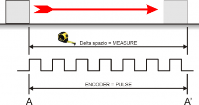
7.6.1 Taratura della risoluzione
 →
→ 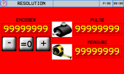
-
Premere il tasto
 (Out analogica +1 Volt), controllare che il valore del campo ENCODER aumenti
 -
Premere il tasto
 (Out analogica -1 Volt), controllare che il valore del campo ENCODER diminuisca
 -
A - A' = Spazio più lungo possibile
-
Segnare la posizione di partenza (A)
-
Azzerare il valore ENCODER:

-
Eseguire il movimento da A ad A'
-
Trascrivere nel campo PULSE, il valore visualizzato nel campo ENCODER
-
Misurare il delta spazio A - A'
-
Scrivere il valore di delta spazio A - A' nel campo MEASURE
Importante:
-
Il valore di PULSE dovrà sempre essere superiore al valore di MEASURE (il valore ottimale è „MEASURE x 10 = PULSE“)
-
Introdurre il valore MEASURE nell'unità di misura scelta. Esempio: se l'unità di misura scelta è 1/10mm e la misura di delta spazio è 133.5mm, introdurre il valore 1335 nel campo MEASURE
-
I valori di Pulse e Misure qui inseriti , verranno trascritti automaticamente nei parametri GP-XX
7.6.2 Taratura P.I.D.
| P.I.D. | |
Descrivere i pulsanti e i parametri
7.6.3 Linearizzazione
| LINEARIZATION | |
Descrivere i parametri e come eseguire la linearizzazione dell'encoder quando non è in asse con il centro banco
Inserire pulsante „ Abilitazioni “
Inserire descrizione delle abilitazioni …ovvero come è stata costruita la macchina vedi pagine iniziali sui tipi di macchine che si possono costruire con questa apparecchiatura
Poi , descrivere come caricare i default
Indicare come settare i parametri che sono specifici per la meccanica predisposta per questa macchina
Quindi si dovrà indicare come verificare gli ingressi e le uscite
8. Diagnostics
8.1 CPU DATA
 | Fw name : firmware in the controller and relative checksum Task time : the average cycle time of the CPU with indexing of the Maximum Time and the Minimum Time for the scan CPU time : total time from when the CPU is in the RUN state (hh:mm) |
8.2 Inputs
| INPUTS | |
 | Visualizzazione dello stato degli ingressi digitali suddivisi per connettore |
 | Visualizzazione del valore degli ingressi analogici |
 | Visualizzazione del valore dell'ingresso BOURNS |
8.3 Outputs
| OUTPUTS | | Visualizzazione dello stato delle uscite digitali suddivise per connettore. |
8.4 Counters
| COUNTERS | |
 | Posizioni di ogni asse in unità di misura lineare o angolare |
 | Stato di attivazione delle fasi encoder. |
 | FOLLERR: = errore di inseguimento attuale MAX: POS:/NEG: = valore minimo e massimo raggiunti dall'errore di inseguimento |
8.5 Analog outputs
| ANALOG OUTS | | Valore di tensione dell'uscita analogica |
★ Sostituire la pagina con quella riportata adattandola a questa specifica applicazione ( presa dalla levigatrice )
★ Scrivere : „ Controllare tutti gli ingressi digitali „
Per risparmiare ingressi ho modificato gli ingressi dei fine corsa degli assi
Per ogni asse non ci sono più due ingressi ma bensì uno solo …a mio avviso più che sufficiente
Poi , ho modificato i Jog …a mio avviso …utilizzando il portale ho visto che è facile sbagliare
è meglio selezionare l'asse e avere una unica interrutore a leva per movimentarlo …questo, a mio avviso favorisce il non fare errori
Poi , non è serio che lo Start e lo Stop macchina sia sullo strumento …quindi ho previsto due ingressi dedicati
Poi , ho modificato gli ingressi di Feedback dell'asse W e Asse H
…spostandoli dalle fasi encoder a degli ingressi digitali.
Nota : quando l'asse H è manuale ….per il feedback del punzone potremo utilizzare i fine corsa 24 e 25 …liberando cosi l'ingresso 23
A questo punto ..rivisti gli ingressi …potremo avere due ingressi liberi …il 23 e il 32 …e le fasi encodere potremo riservarle solo per casi particolari
8.6 Controllo dei finecorsa
Controllo dei finecorsa hardware
Controllo dei finecorsa 0° - 90° del disco
9. Hardware and connections
9.0.1 I/O List
9.0.1.1 Ingressi digitali (n. 32)
| NOME | DESCRIZIONE | MORSETTO | HARDWARE |
|---|---|---|---|
| I 1 | JOG X + (move X in + direction) | CN11 | J1K31-FR30 |
| I 2 | JOG X - (move X in - direction) | ||
| I 3 | JOG Y + (move Y in + direction) | ||
| I 4 | JOG Y - (move Y in - direction) | ||
| I 5 | JOG Z + (move Z in + direction / up) | ||
| I 6 | JOG Z - (move Z in - direction / down) | ||
| I 7 | Start work | ||
| I 8 | Stop work | ||
| I 9 | Enable manual state | CN12 | J1K31-FR30 |
| I 10 | Enable automatic state | ||
| I 11 | Reset work and zero axes | ||
| I 12 | High speed JOG. (ON = high, LOW = slow) | ||
| I 13 | Water pressure OK | ||
| I 14 | Auxiliary OK | ||
| I 15 | Splindle speed ok | ||
| I 16 | Rotation table W in working position | ||
| I 17 | Drivers OK | CN13 | J1K31-FR30 |
| I 18 | Perimetral protection OK | ||
| I 19 | X limit switch | ||
| I 20 | Y limit switch | ||
| I 21 | Z limit switch | ||
| I 22 | Feedback for unlock position 1 (usually 0°) axis W | ||
| I 23 | Feedback for unlock position 1 (usually 90°) axis W | ||
| I 24 | Y position OK for tilting table | ||
| I 25 | Horizontal disk | ||
| I 26 | Vertical disk | CN14 | J1K31-FR30 |
| I 27 | X Homing Switch | ||
| I 28 | Y Homing Switch | ||
| I 29 | Z Homing Switch | ||
| I 30 | W Homing Switch | ||
| I 31 | H Homing Switch | ||
| I 32 | free |
9.0.1.2 Ingressi digitali veloci (n. 4)
| NOME | DESCRIZIONE | MORSETTO | HARDWARE |
|---|---|---|---|
| I01 | Turn revolution sensor | CN11 | J1K31-FR30 |
| I02 | Mill inverter on | CN12 | |
| I03 | Disk inverter on | CN13 | |
| I04 | Inverter ok | CN14 |
9.0.1.3 Ingressi digitali index (n. 1)
| NOME | DESCRIZIONE | MORSETTO | HARDWARE |
|---|---|---|---|
| IDX | free | CN20 | J1K31-FR30 |
9.0.1.4 Digital outputs (n. 32)
| NAME | DESCRIPTION | TERMINAL | HARDWARE |
|---|---|---|---|
| O1 | Automatic cycle active state | CN7 | J1K31-FR30 |
| O2 | free | ||
| O3 | Alarm sound (active according with PG-09 parameter) | ||
| O4 | Rotary table high | ||
| O5 | Rotary table low | ||
| O6 | free | ||
| O7 | Enable X axis | ||
| O8 | Laser 2 | ||
| O9 | Enable Y axis | CN8 | J1K31-FR30 |
| O10 | Break Y axis | ||
| O11 | Enable Z axis | ||
| O12 | Break Z axis | ||
| O13 | Enable W axis | ||
| O14 | Enable movment W axis | ||
| O15 | Break W axis | ||
| O16 | Enable H axis | ||
| O17 | Enable movment H axis | CN9 | J1K31-FR30 |
| O18 | Break H axis | ||
| O19 | EV water | ||
| O20 | Laser 1 | ||
| O21 | Reset drive. (Active for 2 sec when reset active alarms) | ||
| O22 | free | ||
| O23 | End automatic work | ||
| O24 | Machine OK (active if alarm state is not active) | ||
| O25 | Enable Mill inverter | CN10 | J1K31-FR30 |
| O26 | Enable Disk inverter | ||
| O27 | Electrocoil to unlock perimetral protections | ||
| O28 | free | ||
| O29 | Active lock position 1 (usually 0°) for W axis | ||
| O30 | Active lock position 2 (usually 90°)for W axis | ||
| O31 | Active lock position 1 (usually 0°) for H axis | ||
| O32 | Active lock position 2 (usually 90°)for H axis |
9.0.1.5 Quadrature encoder inputs (n° 8)
| Nome | Description | Connector | Hardware |
|---|---|---|---|
| CNT01 | position X | CN15 | J1K31-FR30 |
| CNT02 | position Y | CN16 | |
| CNT03 | position Z | CN17 | |
| CNT04 | position W | CN18 | |
| CNT05 | position H | CN19 | |
| CNT06 | interpolation override burns | CN20 | |
| CNT07 (*) | free | CN21 | |
| CNT08 (*) | free | CN22 |
(*) Not available in FR hardware version
9.0.1.6 Analog inputs (n. 4)
| Name | Description | Connector | Hardware |
|---|---|---|---|
| AI1 | Potentiometer to set the X speed in cut direction | CN28 | J1K31-FR30 |
| AI2 | Potentiometer to set the X speed in opposite cut direction | ||
| AI3 | Spindle motor actual current | CN29 | |
| AI4 | Spindle actual rotation speed |
9.0.1.7 Analog outputs (n. 8)
| Nome | Description | Connector | Hardware |
|---|---|---|---|
| AO1 | X Speed | CN26 | J1K31-FR30 |
| AO2 | Y Speed | ||
| AO3 | Z Speed | ||
| AO4 | W Speed | ||
| AO5 | H Speed | CN27 | J1K31-FR30 |
| AO6 | Spindle rotation speed set | ||
| AO7 (*) | free | ||
| AO8 (*) | free |
(*) Not available in FR hardware version
( 1 ) or horizontal disk if parameter PH3 ENCODER is zero
( 2 ) or vertical disk if parameter PH3 ENCODER is zero
Note
★ NC - O significa contatto Normalmente chiuso ( Closed ) , l'azione verrà fatta quando il contatto si apre ( Open )
★ NO - C significa contatto Normalmente aperto ( Open ) , l'azione verrà fatta quando il contatto si chiude ( Closed )
★ NO - C significa contatto Normalmente aperto ( Open ), l'azione verrà fatta quando il contatto si chiude ( Closed ) in modo continuo (Continuous )
Uscite digitali
10. Homing
| | |
| Homing abilitato | |
| Homing disabilitato | |
| Homing non eseguito | |
| Homing eseguito correttamente | |
 | Delta di errore |
ALWAYS run the Homing procedure before going from HOMING to MANUAL.
Failure to do the Homing will limit the machine operation. These limits are in the Setup section protected by password.
10.1 Esecuzione dell'homing
-
Selezionare gli assi interessati

-
Attivare l'ingresso
-
Se la procedura si conclude correttamente si illumina il led

-
Se la procedura non si conclude correttamente il led resta spento

-
A lato risulta l'errore Delta
11. LAVORAZIONI
11.1 Tagli multipli
| | |
11.1.1 Senza banco girevole
| LAVORAZIONE SENZA BANCO GIREVOLE | ||
|---|---|---|
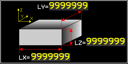
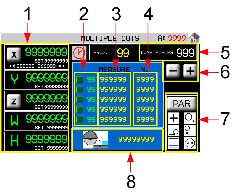 | 1 Conteggi e quote target degli assi 2 Passo in esecuzione 3 Larghezza (Y) taglio 4 Numero pezzi da eseguire 5 Contatore pezzi eseguiti 6 Scorrimento passi di lavorazione 7 Parametri della lavorazione 8 Profondità di taglio (Z) |
|
11.1.2 Con banco girevole

| LAVORAZIONE CON BANCO GIREVOLE | ||
|---|---|---|
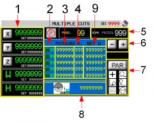 | 1 Conteggi e quote target degli assi 2 Passo in esecuzione 3 Larghezza (Y) taglio 4 Numero pezzi da eseguire 5 Rotazione (W) banco 6 Contatore pezzi eseguiti 7 Scorrimento passi di lavorazione 8 Parametri della lavorazione 9 Profondità di taglio (Z) |
|
11.1.3 Axes's work parameters
 | Accesso alla pagina di apprendimento delle due quote di X di inizio e fine taglio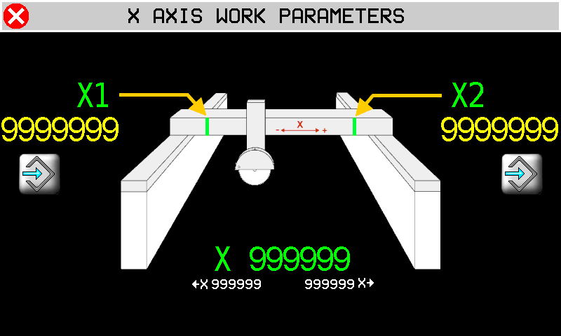 NEL CASO SIA IMPOSTATA UNA LAVORAZIONE SENZA BANCO GIREVOLE 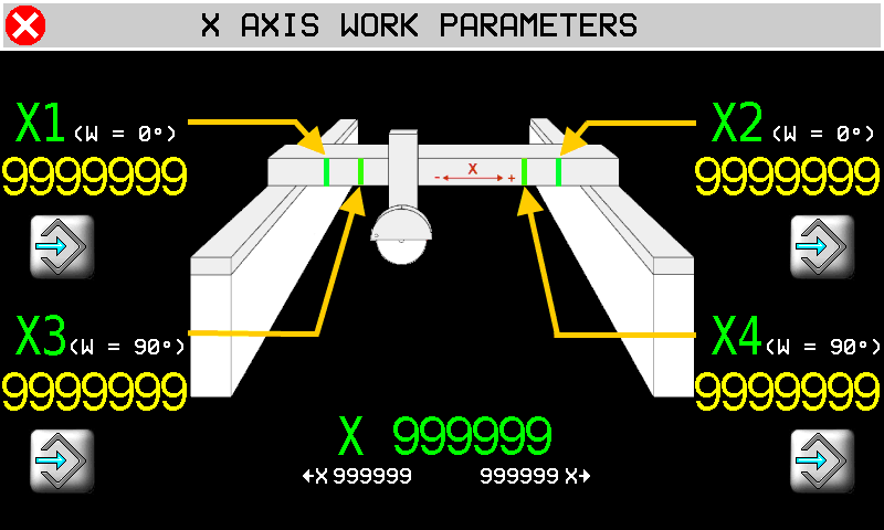 NEL CASO SIA IMPOSTATA UNA LAVORAZIONE CON BANCO GIREVOLE  Apprendimento della quota Apprendimento della quotaN.B.: la lama esce velocemente dal blocco per uno spazio pari al raggio della lama stessa prima di arrivare alle quote X1 o X2, oppure X3 o X4. |
 | Accesso alla pagina di impostazione delle quote di Y.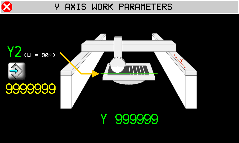 Apprendimento della quota Apprendimento della quotaY2: Quota di partenza dell'asse Y con il banco (W) a 90° NB. Valida solo per il taglio CON BANCO GIREVOLE. |
 | Accesso alla pagina di impostazione degli incrementi di Z.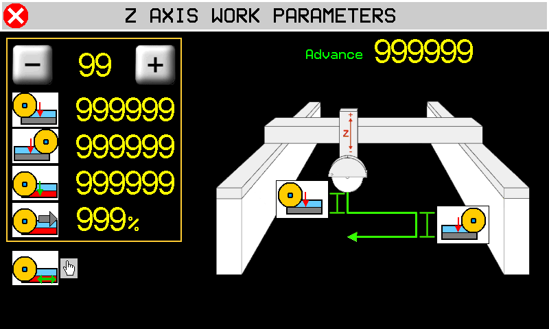        |
11.1.4 Parametri della lavorazione
 | 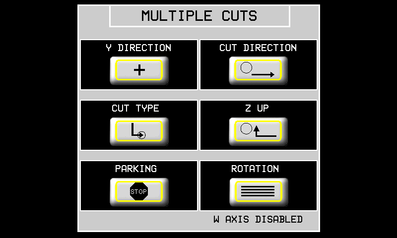 |
| DIREZIONE ASSE Y |  L'asse Y si sposta in POSITIVO alla fine del taglio L'asse Y si sposta in POSITIVO alla fine del taglio L'asse Y si sposta in NEGATIVO alla fine del taglio L'asse Y si sposta in NEGATIVO alla fine del taglio |
| DIREZIONE TAGLIO |  Direzione taglio solo verso X+ Direzione taglio solo verso X+ Taglio BILATERALE Taglio BILATERALE |
| TIPO TAGLIO |  Taglio SINGOLO Taglio SINGOLO Taglio a PASSATE Taglio a PASSATE |
| RISALITA Z |  L'Asse Z risale DOPO che l'Asse X ha raggiunto il finecorsa minimo L'Asse Z risale DOPO che l'Asse X ha raggiunto il finecorsa minimo Gli assi X e Z escono dal blocco CONTEMPORANEAMENTE Gli assi X e Z escono dal blocco CONTEMPORANEAMENTE |
| PARCHEGGIO |  A fine programma gli assi rimangono nell'ultima posizione raggiunta A fine programma gli assi rimangono nell'ultima posizione raggiunta A fine programma gli assi si portano alle quote di PRESET A fine programma gli assi si portano alle quote di PRESET |
| ROTAZIONE |  Lavorazione SENZA BANCO GIREVOLE Lavorazione SENZA BANCO GIREVOLE Se abilitata in SETUP GENERALE, lavorazione CON BANCO GIREVOLE Se abilitata in SETUP GENERALE, lavorazione CON BANCO GIREVOLE |
11.2 Inclinated Cuts

| | |
| NEL CASO SIA IMPOSTATO L'ASSE H SENZA ENCODER | |
|---|---|
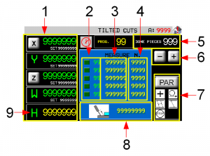 | 1 Conteggi e quote target degli assi 2 Passo in esecuzione 3 Larghezza (Y) taglio 4 Numero pezzi da eseguire 5 Contatore pezzi eseguiti 6 Scorrimento passi di lavorazione 7 Parametri della lavorazione 8 Profondità (Z) tagli 9 Asse H senza encoder |
| NEL CASO SIA IMPOSTATO L'ASSE H CON ENCODER | |
|---|---|
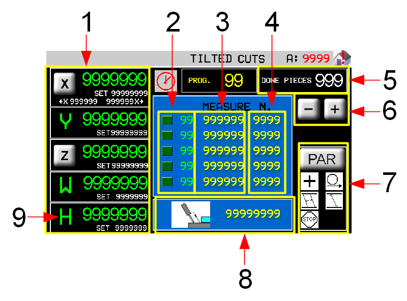 | 1 Conteggi e quote target degli assi 2 Passo in esecuzione 3 Larghezza (Y) taglio 4 Numero pezzi da eseguire 5 Contatore pezzi eseguiti 6 Scorrimento passi di lavorazione 7 Parametri della lavorazione 8 Profondità (Z) tagli 9 Asse H con encoder |
11.2.1 Parametri di lavoro degli assi
VEDI IL CAPITOLO Axes's work parameters
11.2.2 Parametri della lavorazione
| | 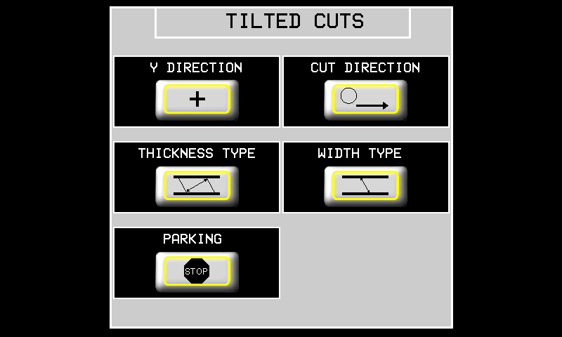 |
| DIREZIONE ASSE Y | L'asse Y si sposta in POSITIVO alla fine del taglio L'asse Y si sposta in NEGATIVO alla fine del taglio |
| DIREZIONE TAGLIO | Direzione taglio solo verso X+ Taglio BILATERALE |
| TIPO SPESSORE |  Lo spessore è la DISTANZA misurata perpendicolarmente ai tagli. Lo spessore è la DISTANZA misurata perpendicolarmente ai tagli. Lo spessore è la DISTANZA misurata lungo la superficie del blocco. Lo spessore è la DISTANZA misurata lungo la superficie del blocco. |
| TIPO PROFONDITA' |  La profondità è quanto la lama entra effettivamente nel blocco. La profondità è quanto la lama entra effettivamente nel blocco. La profondità è misurata perpendicolarmente al blocco La profondità è misurata perpendicolarmente al blocco |
| PARCHEGGIO | A fine programma gli assi rimangono nell'ultima posizione raggiunta A fine programma gli assi si portano alle quote di PRESET |
11.3 Programmi di lavoro
 |  |  |
 |  |  |
11.3.1 New program lavorazione profili
| | |
||
| | |  |
|
| |
|||
| |
|||
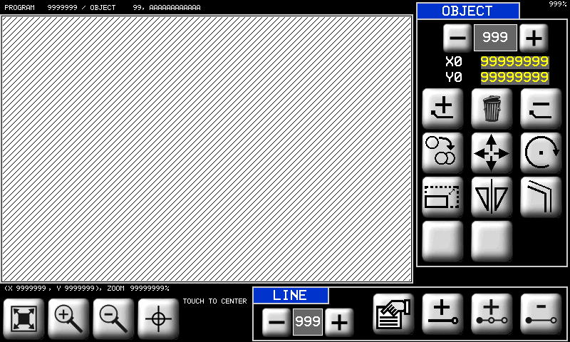
11.3.1.1 Drawing Editor
 | 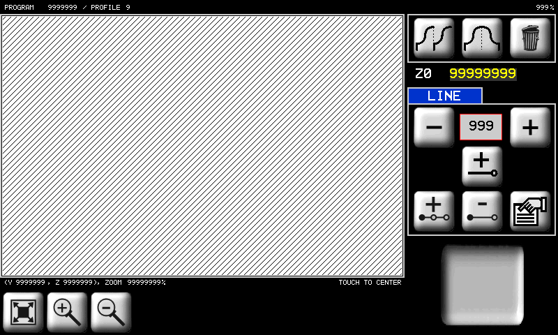 |
 | è la coordinata Z del punto iniziale del primo tratto. La coordinata Y del punto invece è sempre per convenzione pari a 0. | |
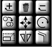
 | Strumenti per la gestione dei tratti che compongono il profilo. Per tratto si intende un segmento od un arco. | |
  | Tasti per scorrere e selezionare i tratti disegnati. | |
 | Tasto per aggiungere un tratto in coda a quelli già presenti. | |
 | Tasto per inserire un tratto precedente al tratto selezionato in quel momento. | |
 | Tasto per cancellare il tratto selezionato (verrà chiesta conferma). | |
 | Tasto per accedere alla pagina delle proprietà del tratto selezionato ed eventualmente modificarle. | |
 | Strumento di copia di tutti i tratti da quello selezionato fino all'ultimo presente. | |
 | Strumento di copia simmetrica di tutti i tratti da quello selezionato all'ultimo presente. | |
 | Cancella il profilo. Il profilo verrà completamente cancellato (verrà chiesta conferma). | |
 | Lo zoom viene adattato per far sì che il profilo venga visualizzato interamente nell'area di disegno. | |
  | Zoom-in e Zoom-out del profilo. | |
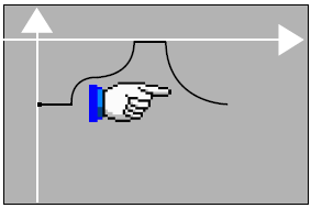
 | Questa icona serve per indicare che piano sta visualizzando in quel momento il disegno piano YZ: forma del profilo. piano XZ. andamento del taglio. piano XZ. andamento del taglio. |
|
| |  |
Inserire le coordinate del punto finale del nuovo tratto (il punto iniziale è il punto finale del precedente). Gli altri strumenti di questa pagina sono:
      | Tasti per accedere alle pagine di inserimento / modifica delle proprietà dei tratti. In seguito descriveremo in dettaglio ogni tipo di tratto. |
 / / | Selettore per inserire le quote in modo assoluto rispetto al sistema di riferimento del disegno oppure in modo incrementale rispetto al punto di inizio del tratto. |
 | Tasto per confermare l'inserimento del tratto oppure le modifiche eseguite. |
 | Se non si vuole confermare si può tornare alla visualizzazione precedente con questo tasto. |
I tipi di tratto e i parametri relativi sono i seguenti:
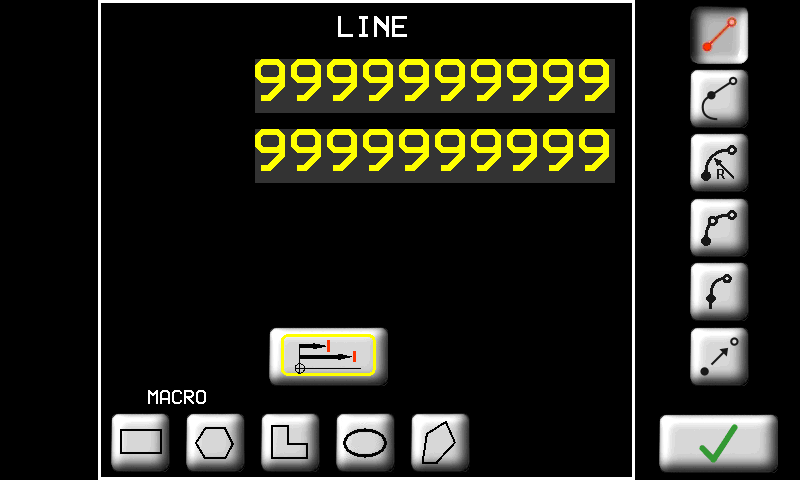
| TASTO | NOME DEL TRATTO | PARAMETRO |
|---|---|---|
| LINEA. | Segmento di retta. E' necessario inserire le coordinate del punto finale del segmento. |
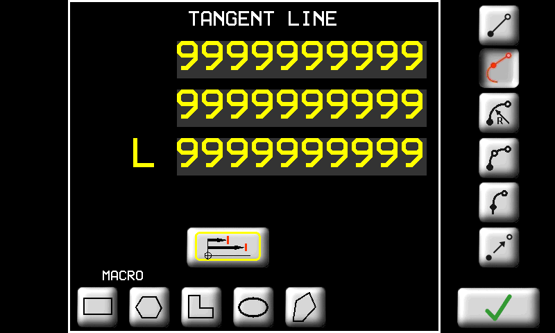
| LINEA TANGENTE | Segmento di retta tangente al tratto precedente. E' necessario inserire uno dei seguenti dati a scelta (gli altri verranno ricalcolati di conseguenza): - Ascissa; - Ordinata; - oppure Lunghezza del tratto. |
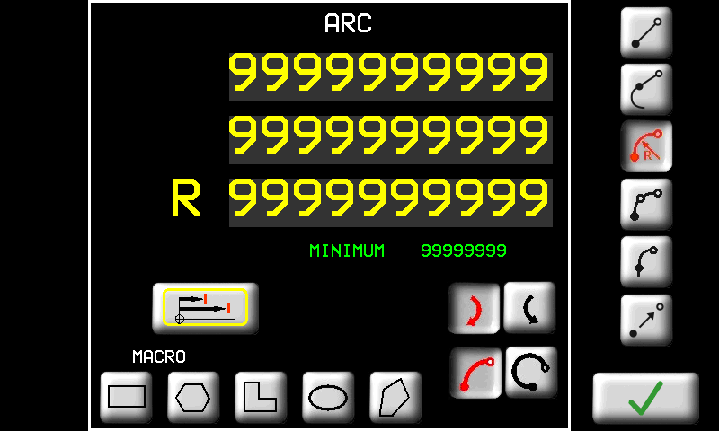
| ARCO | Arco di circonferenza. Si devono inserire le coordinate del punto finale del tratto e il raggio. Inoltre è necessario inserire il verso dell'arco: -  orario; orario;-  antiorario. antiorario.-  arco corto; arco corto;-  arco lungo; arco lungo;Nella pagina viene visualizzato anche il raggio minimo che è possibile inserire al di sotto del quale l'arco non può essere realizzato. |
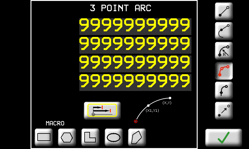
| ARCO 3 PUNTI | Arco di circonferenza per tre punti. Si devono inserire le coordinate del punto intermedio e del punto finale dell'arco. |
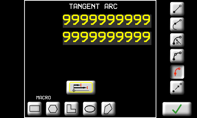
| ARCO TANGENTE | Arco di circonferenza tangente al tratto precedente. E' necessario inserire le coordinate del punto finale del tratto. Raggio e verso dell'arco sono calcolati automaticamente per mantenere la tangenza al tratto precedente. |
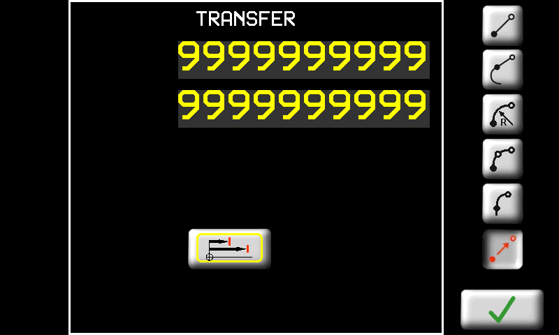
| TRASFERIMENTO | Spostamento senza lavorazione. Si devono inserire le coordinate del punto da cui riprendere la lavorazione. La zona di materiale relativa allo spostamento non verrà lavorata. |
In caso di tratto del profilo in sottosquadra, il software correggerà automaticamente.
 | |
 |  |
 |  |
 |  |
 |  |
 |  |
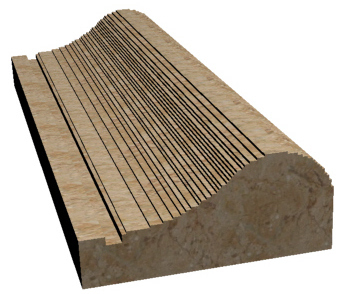
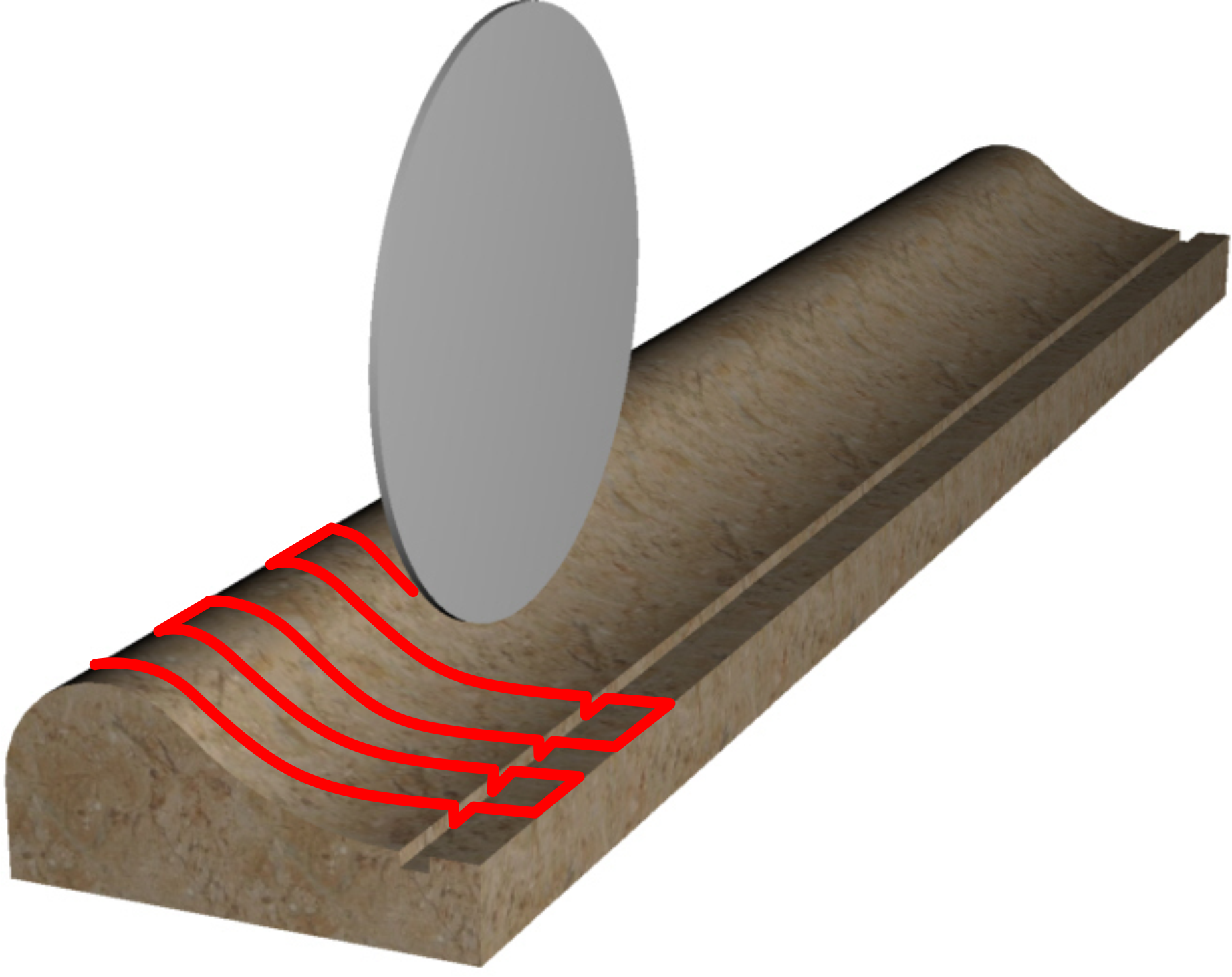
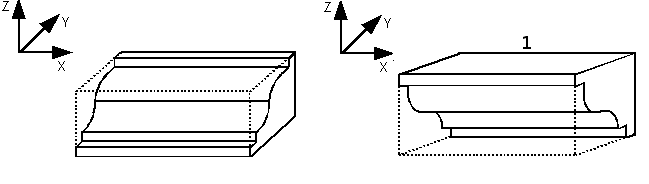
Profili con tagli rettilinei
Per ottenere una sagomatura con tagli rettilinei, programmare il profilo solamente sul piano Y-Z
-
sia con lama verticale

-
che con lama orizzontale

Non si deve assolutamente disegnare alcun profilo negli altri piani.
Profili con tagli curvilinei
Per ottenere una sagomatura con tagli rettilinei, programmare il profilo sul piano Y-Z
-
sia con lama verticale
-
che con lama orizzontale
Inoltre è necessario disegnare l'andamento dei tagli:
-
sul piano X-Z se si usa la lama verticale
 oppure
 -
sul piano X-Y se si usa la lama orizzontale

Per effettuare il cambio di piano è sufficiente toccare l'immagine stessa.
11.3.1.2 Work cycle - Profiles


 | 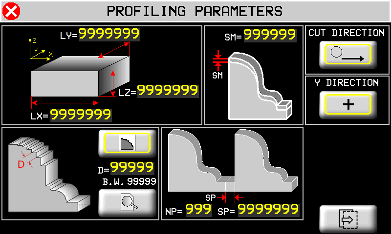   |
La lavorazione di spatolatura NON è possibile se i profili vengono eseguiti con tagli curvilinei.
 | Dimensioni del pezzo che si vuole lavorare. Le dimensioni servono per disegnare un rettangolo sovrapposto al profilo disegnato che indica se le dimensioni sono sufficienti per contenere il profilo stesso |
 | Sovramateriale. I tagli eseguiti lasciano del materiale rispetto alla misura finale. |
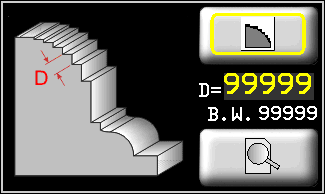 | Strategia di scelta dei tagli da eseguire. I tagli da eseguire possono essere scelti secondo due strategie diverse:   1. 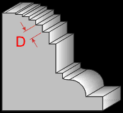 a passo D lungo il profilo; a passo D lungo il profilo;2. 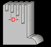 a passo D in direzione Y. a passo D in direzione Y. |
 | Anteprima. Premendo questo tasto è possibile visualizzare un'anteprima dei tagli che verranno eseguiti. |
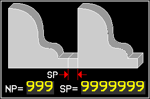 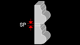 | Ripetizioni. E' possibile ripetere il profilo programmato un numero NP di volte ad una distanza SP tra una ripetizione e l'altra. |
| Taglio eseguito solo nella direzione di taglio e ritorno a vuoto - Taglio eseguito sia nella direzione di taglio che anche nella direzione opposta al taglio. Con questa selezione l'asse Y avanza anche quando l'asse X si trova a destra del pezzo da tagliare. |
| Direzione di movimento dell'asse Y durante questo ciclo automatico. |
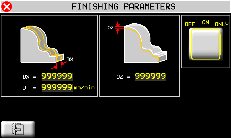
 | next page |
 | previous page |
 | DX: spazio X tra una passata di spatolatura e la successiva. V: velocità massima di interpolazione tra gli assi Y e Z durante la spatolatura. |
 | Offset verticale di esecuzione delle passate della spatolatura. Con un valore negativo le passate vengono eseguite più basse. |
 | Selettore per programmare la modalità con cui viene attivata la procedura di spatolatura: OFF : spatolatura disabilitata; CONTINUA: la spatolatura viene eseguita in modo automatico dopo la profilatura. SOLO: viene eseguita solo la spatolatura senza eseguire la profilatura. |
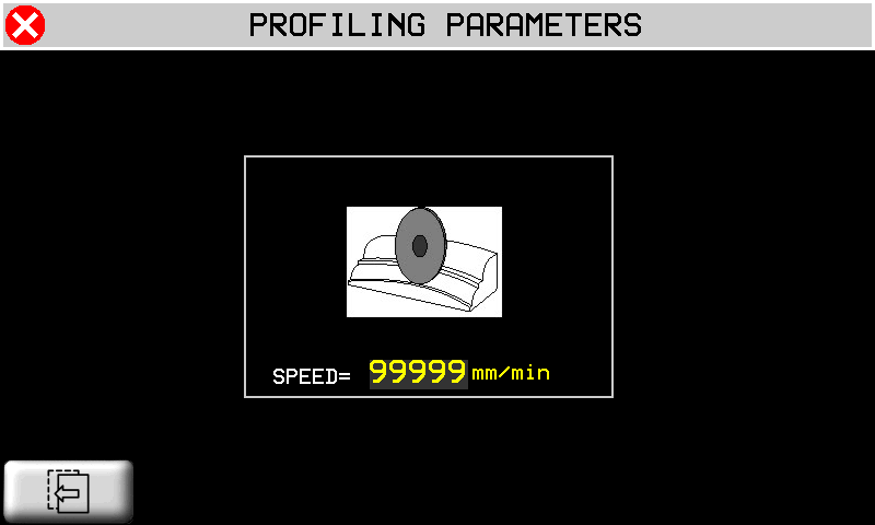
 | Nel caso di tagli curvilinei, in questa pagina si deve inserire la velocità massima con cui verranno eseguiiti i tagli. |
11.3.2 New program fresatura
| | |
||
 |  | |
|
|
|||
 | Import from Memory Card |
 | Save a program |
11.3.2.1 Milling drawing editor
| |  |
Pagina di disegno delle geometrie. il disegno, per convenzione, deve essere eseguito nel quadrante con X e Y positive (vedi figura). Nel seguito descriveremo le parti di questo editor. Alcune funzionalità sono in comune con l'editor dei profili.
 | Selettore delle geometrie presenti. Permette di scorrere le geometrie presenti per poterle selezionare. La geometria presente viene disegnata con colore nero. Mentre le altre sono disegnate in giallo. Un programma vuoto non contiene nessuna geometria. Si veda in seguito come crearne una nuova. |
 | Coordinate del punto iniziale della geometria selezionata. Sul disegno tale punto è indicato con il quadrato nero. |
 | Strumenti per le geometrie. |
 Crea una nuova geometria. Inserisce il primo punto di una nuova geometria alle coordinate (0, 0). Crea una nuova geometria. Inserisce il primo punto di una nuova geometria alle coordinate (0, 0). |
|
 Elimina la geometria selezionata. Nel caso in cui ci sia una lavorazione di TAGLIO già associata alla geometria che si vuole eliminare, verrà eliminata anche tale lavorazione (viene chiesta conferma). Elimina la geometria selezionata. Nel caso in cui ci sia una lavorazione di TAGLIO già associata alla geometria che si vuole eliminare, verrà eliminata anche tale lavorazione (viene chiesta conferma). |
|
| Cancella tutte le geometrie presenti. Come la funzione precedente, ma valida per tutte le geometrie presenti nel programma. |
|
 Copia geometria. Copia la geometria selezionata in una posizione inserita. Copia geometria. Copia la geometria selezionata in una posizione inserita. |
|
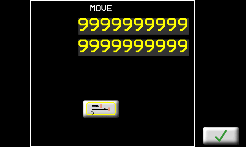
 Sposta geometria. Sposta la geometria selezionata in una posizione inserita. Sposta geometria. Sposta la geometria selezionata in una posizione inserita. |
|
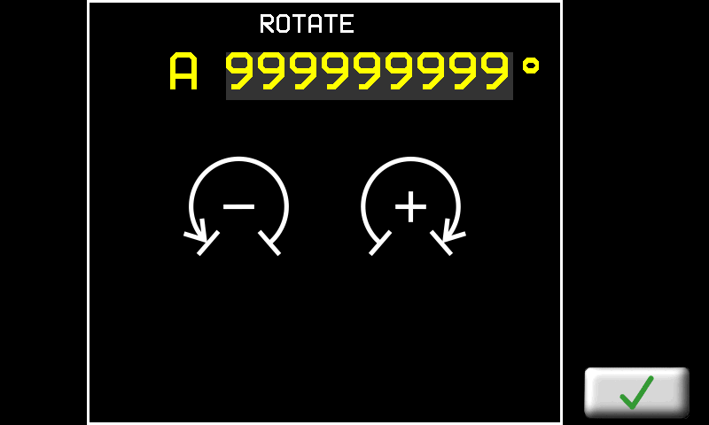
 Ruota geometria. Ruota la geometria selezionata di un angolo inserito. Il punto di rotazione è il primo punto della geometria. Ruota geometria. Ruota la geometria selezionata di un angolo inserito. Il punto di rotazione è il primo punto della geometria. |
|
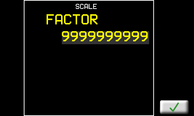
 Scala geometria. Trasforma la geometria selezionata scalandola di un fattore inserito. Scala geometria. Trasforma la geometria selezionata scalandola di un fattore inserito. |
|
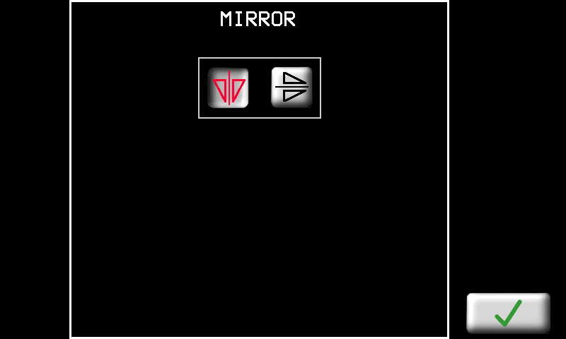
 Specchia. Ribalta in modo simmetrico la geometria selezionata secondo un asse verticale od orizzontale. Specchia. Ribalta in modo simmetrico la geometria selezionata secondo un asse verticale od orizzontale. |
|
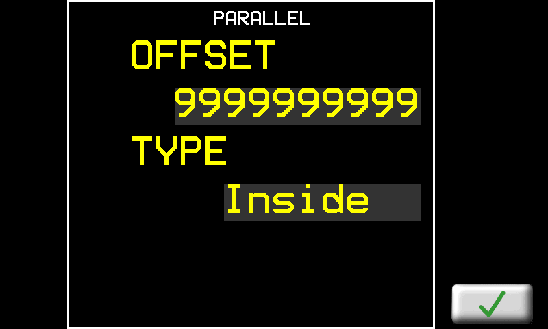
 Parallelo. Crea una nuova geometria partendo da quella selezionata e creandone una parallela interna od esterna con un offset inserito. Parallelo. Crea una nuova geometria partendo da quella selezionata e creandone una parallela interna od esterna con un offset inserito. |
|
 | Strumenti per la gestione dei tratti che compongono la geometria. Per tratto si intende un segmento. |
| Tasti per scorrere e selezionare i tratti disegnati. |
|
| Tasto per aggiungere un tratto in coda a quelli già presenti. |
|
| Tasto per inserire un tratto precedente al tratto selezionato in quel momento. |
|
| Tasto per cancellare il tratto selezionato (verrà chiesta conferma). |
|
| Tasto per accedere alla pagina delle proprietà del tratto selezionato ed eventualmente modificarle. |
|
| | Lo zoom viene adattato per far sì che il profilo venga visualizzato interamente nell'area di disegno. |
| | Zoom-in e Zoom-out del profilo. |
 |  |
 | Tocco sull'area di disegno: il punto che viene toccato viene posizionato al centro dell'area di disegno. In questo modo è possibile zoomare il particolare interessato. |
 |  |
| |  |
| |  |
 |  |
 |  |
 |  |
Per disegnare è necessario inserire una successione di tratti premendo il tasto . Quando si preme questo tasto appare la seguente pagina:
| MACRO | Funzioni automatiche per la composizione di geometrie complesse: |
|---|---|
 | Rettangolo. E' necessario inserire l'altezza e la larghezza del rettangolo che si vuole creare.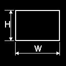 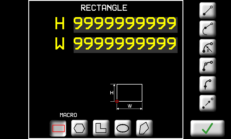 |
 | Poligono regolare. E' necessario inserire il numero di lati N e in alternativa il raggio R oppure la lunghezza del lato L. 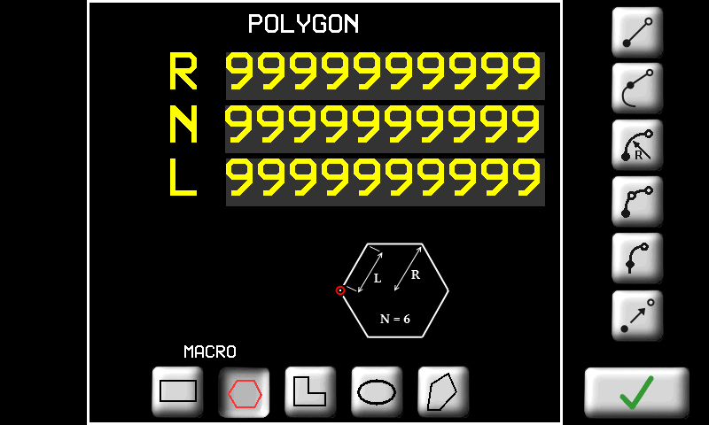 |
 | Forma ad “L”. E' necessario inserire le dimensioni come in figura: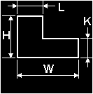 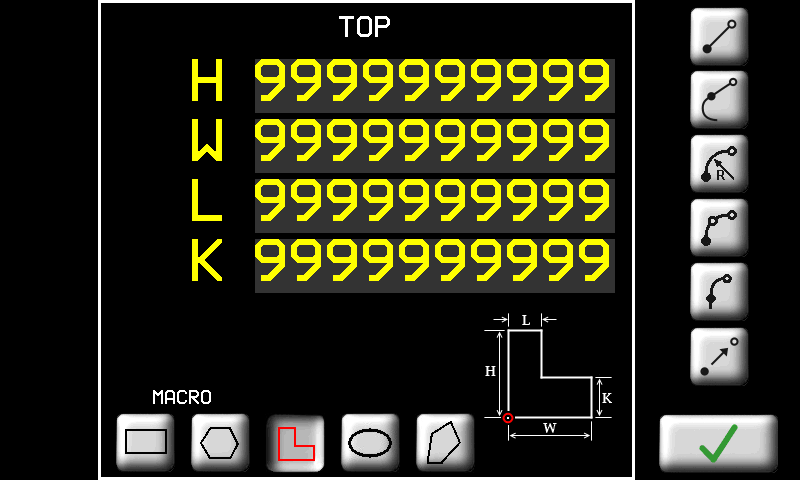 |
 | Forma ad ellisse. E' necessario inserire le dimensioni come in figura: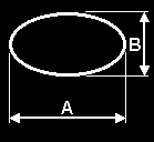 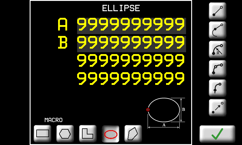 |
 | Pedoca. E' necessario inserire le dimensioni come in figura: 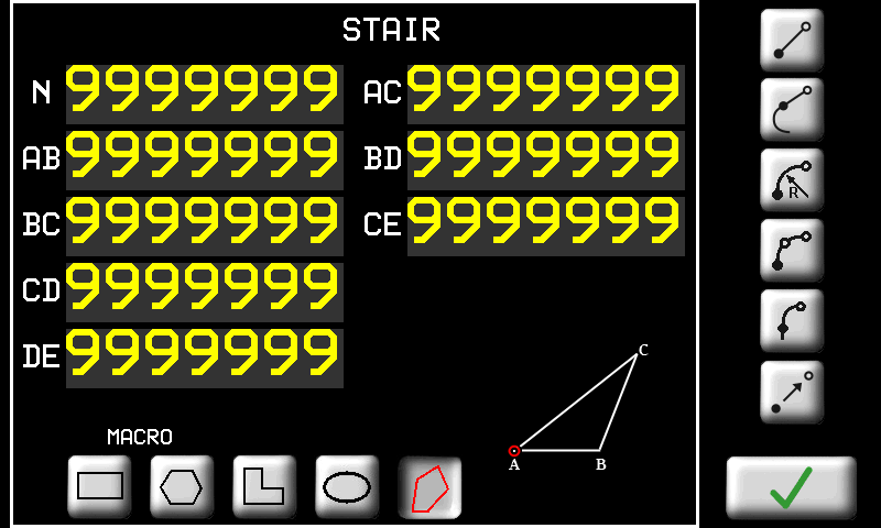 |
| | Tasti per accedere alle pagine di inserimento / modifica delle proprietà dei tratti. In seguito descriveremo in dettaglio ogni tipo di tratto. |
| / | Selettore per inserire le quote in modo assoluto rispetto al sistema di riferimento del disegno oppure in modo incrementale rispetto al punto di inizio del tratto. |
| Tasto per confermare l'inserimento del tratto oppure le modifiche eseguite. |
| TASTO | NOME DEL TRATTO | PARAMETRO |
|---|---|---|
| LINEA. | Segmento di retta. E' necessario inserire le coordinate del punto finale del segmento. |
| LINEA TANGENTE | Segmento di retta tangente al tratto precedente. E' necessario inserire uno dei seguenti dati a scelta (gli altri verranno ricalcolati di conseguenza): - Ascissa; - Ordinata; - oppure Lunghezza del tratto. |
| ARCO | Arco di circonferenza. Si devono inserire le coordinate del punto finale del tratto e il raggio. Inoltre è necessario inserire il verso dell'arco: - orario;- antiorario.- arco corto;- arco lungo;Nella pagina viene visualizzato anche il raggio minimo che è possibile inserire al di sotto del quale l'arco non può essere realizzato. |
| ARCO 3 PUNTI | Arco di circonferenza per tre punti. Si devono inserire le coordinate del punto intermedio e del punto finale dell'arco. |
| ARCO TANGENTE | Arco di circonferenza tangente al tratto precedente. E' necessario inserire le coordinate del punto finale del tratto. Raggio e verso dell'arco sono calcolati automaticamente per mantenere la tangenza al tratto precedente. |
| | |
| | |
| | |
| | |
| | |
11.3.2.2 Work Cycle - Tops
| |  |
| Simbolo | Significato |
|---|---|
 | Il tratto selezionato viene rappresentato con il colore rosso. |
 | Se il tratto selezionato è un “arco a 3 punti”, viene rappresentato il punto intermedio. |
 |
Una volta disegnate le geometrie è possibile associare ad ognuna di esse una o più lavorazioni. La successione delle lavorazioni compone il programma di lavoro. Le lavorazioni saranno poi eseguite nell'ordine in cui appaiono nella lista.
 | Scelta del gruppo di 5 lavorazioni | |
 | Aggiunge una lavorazione | |
 | Cancella una lavorazione | |
| Modifica della proprietà della lavorazione selezionata | |
| Lo zoom viene adattato per far sì che il profilo venga visualizzato interamente nell'area di disegno. | |
| | Zoom-in e Zoom-out del profilo. | |
 | Selezione delle lavorazioni con tocco | |
| Lavorazione programmata o abilitata (attiva con tocco per 3 sec.) | ||
| La geometria associata è stata modificata | ||
| Lavorazione non abilitata all'esecuzione (disattiva con tocco per 3 sec.) | ||
| Lavorazione non programmata | ||
| Lavorazione non programmata e non abilitata | ||
| Lavorazione abilitata ma non programmata | ||
| | 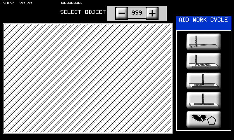 |
In questa pagina è possibile associare un tipo di lavorazione ad una delle geometrie disegnate. Sono presenti i seguenti tasti:
 | |
| | Cut |
 | Milling |
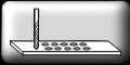
 | Pocketing |
 | Pocket 3D |
 | Poligon cut |
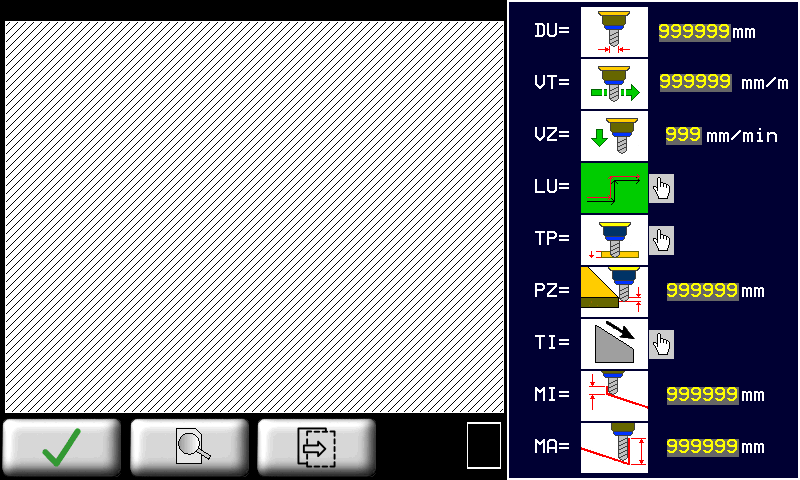
11.3.2.2.1 CUT - Parametri di lavorazione taglio

 |  |
|
| |  |
|
 | |
| | |
| | |
 | DU (Diametro utensile): Impostare il diametro dell'utensile che verrà usato per effettuare la lavorazione. |
 | VT (Velocità taglio): Impostare una velocità adeguata al tipo di lavorazione da effettuare. |
 | VZ (Vel. Z-): E' la velocità con cui l'utensile viene mosso nella direzione Z- (verso il basso). |
| LU (Utensile dx/sx): Indica la posizione dell'utensile rispetto alla geometria da lavorare. -  Posizione sinistra dell'utensile rispetto alla geometria da lavorare. Posizione sinistra dell'utensile rispetto alla geometria da lavorare.-  Posizione destra dell'utensile rispetto alla geometria da lavorare. Posizione destra dell'utensile rispetto alla geometria da lavorare.Toccare immagine per modificare. Quando l'immagine lampeggia premere  per cambiare per cambiare |
|
| TP(Tipo passata): -  SINGOLA: la profondità Z impostata viene raggiunta con un'unica passata dell'utensile sul percorso calcolato. SINGOLA: la profondità Z impostata viene raggiunta con un'unica passata dell'utensile sul percorso calcolato.-  MULTIPLA: la profondità Z impostata viene raggiunta attraverso una ripetizione del percorso a profondità via via maggiori. MULTIPLA: la profondità Z impostata viene raggiunta attraverso una ripetizione del percorso a profondità via via maggiori.Toccare immagine per modificare. Quando l'immagine lampeggia premere per cambiare |
|
 | PZ(Passo Z): nel caso di Tipo passata = Multipla, esso è l'incremento della profondità di Z tra una passata e la successiva. |
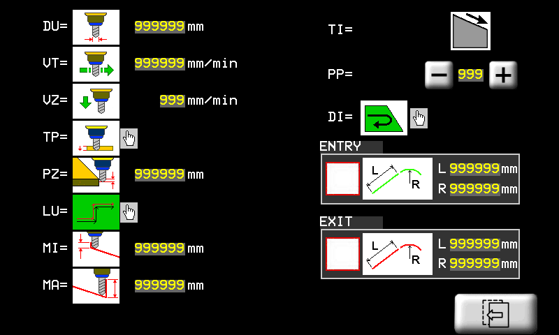
| TI(Inclinazione del taglio): La profondità del taglio non è costante ma ha un verso di inclinazione -  la profondità aumenta con X crescenti. la profondità aumenta con X crescenti.-  la profondità aumenta con X decrescenti. la profondità aumenta con X decrescenti.-  la profondità aumenta con Y decrescenti. la profondità aumenta con Y decrescenti.-  la profondità aumenta con Y crescenti. la profondità aumenta con Y crescenti. |
|
 | MI(Minima Profondità): è la profondità più bassa ottenuta durante il taglio. |
 | MA(Massima Profondità): è la profondità più alta ottenuta durante il taglio. Se le due profondità MI e MA sono impostae uguali, il taglio viene eseguito tutto alla stessa profondità. In ogni caso il taglio viene realizzato con un unica passata oppure a più passate a seconda del parametro TP. |
 | DI(Direzione): Premendo il tasto corrispondente è possibile scegliere la direzione che l'utensile seguirà per eseguire la lavorazione. Questa funzione è valida solo in caso di geometrie chiuse e permette di ottenere un cambio di senso vero e proprio (orario/antiorario). |
 | PP(Primo punto): E' possibile scegliere il punto iniziale della lavorazione. Questo punto è quello che verrà lavorato per primo. Geometria di tipo chiuso Geometria di tipo chiuso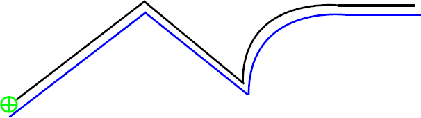 Geometria di tipo aperto Geometria di tipo aperto Geometria Geometria Percorso utensile Percorso utensileNota: Nel caso di geometrie “aperte”, è possibile scegliere come punto di inizio solo uno dei due estremi della geometria.  ORARIO ORARIO ANTIORARIO ANTIORARIO Direzione DirezioneLa funzione non è valida per geometrie aperte. |
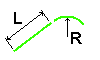 | Entrata/uscita: Con questi parametri è possibile inserire dei tratti di ingresso/uscita aggiuntivi in modo da raccordare meglio la lavorazione con il percorso dell'utensile. I tratti sono composti da un segmento rettilineo (L) ed eventualmente un arco di raggio (R). (Nel primo esempio sono state impostate solo le lunghezze L delle linee, mentre nel secondo sono stati impostati anche i raggi R degli archi di raccordo).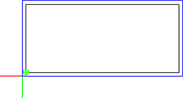 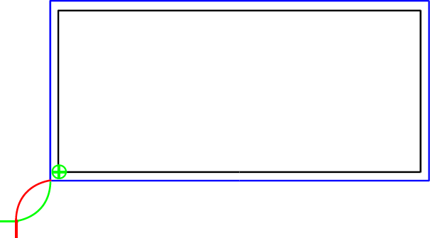  Percorso entrata Percorso uscita Percorso entrata Percorso uscitaNota: Nel caso in cui la geometria sia chiusa e l'utensile interno ad essa, il punto iniziale non dovrà essere posto sugli angoli (vedi figura). 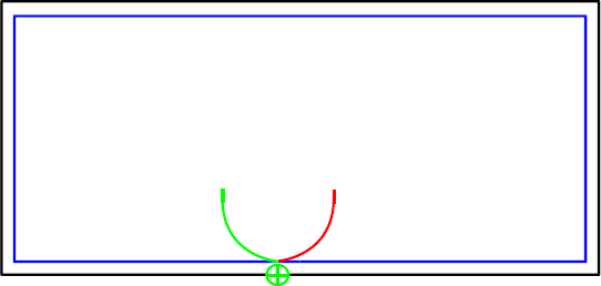 |
Limitazioni alla compensazione utensile
La compensazione del diametro dell'utensile nelle lavorazioni 2D consente di determinare il percorso che l'utensile di un certo diametro deve compiere per ottenere le dimensioni del pezzo inserite.
Una volta impostato il diametro dell'utensile nella apposita pagina della lavorazione 2D, viene proposto all'operatore il percorso utensile disegnato con un tratto blu. L'operatore deve eseguire un controllo visivo della correttezza del percorso utensile.
Tale controllo è necessario per verificare la correttezza del percorso nel caso in cui si siano verificati i casi limite di seguito elencati:
Percorso utensile che si chiude su se stesso:

In questo caso NON viene segnalato un errore nella compensazione utensile.
I casi limite descritti potranno essere risolti nei futuri sviluppi del software per la compensazione utensile.
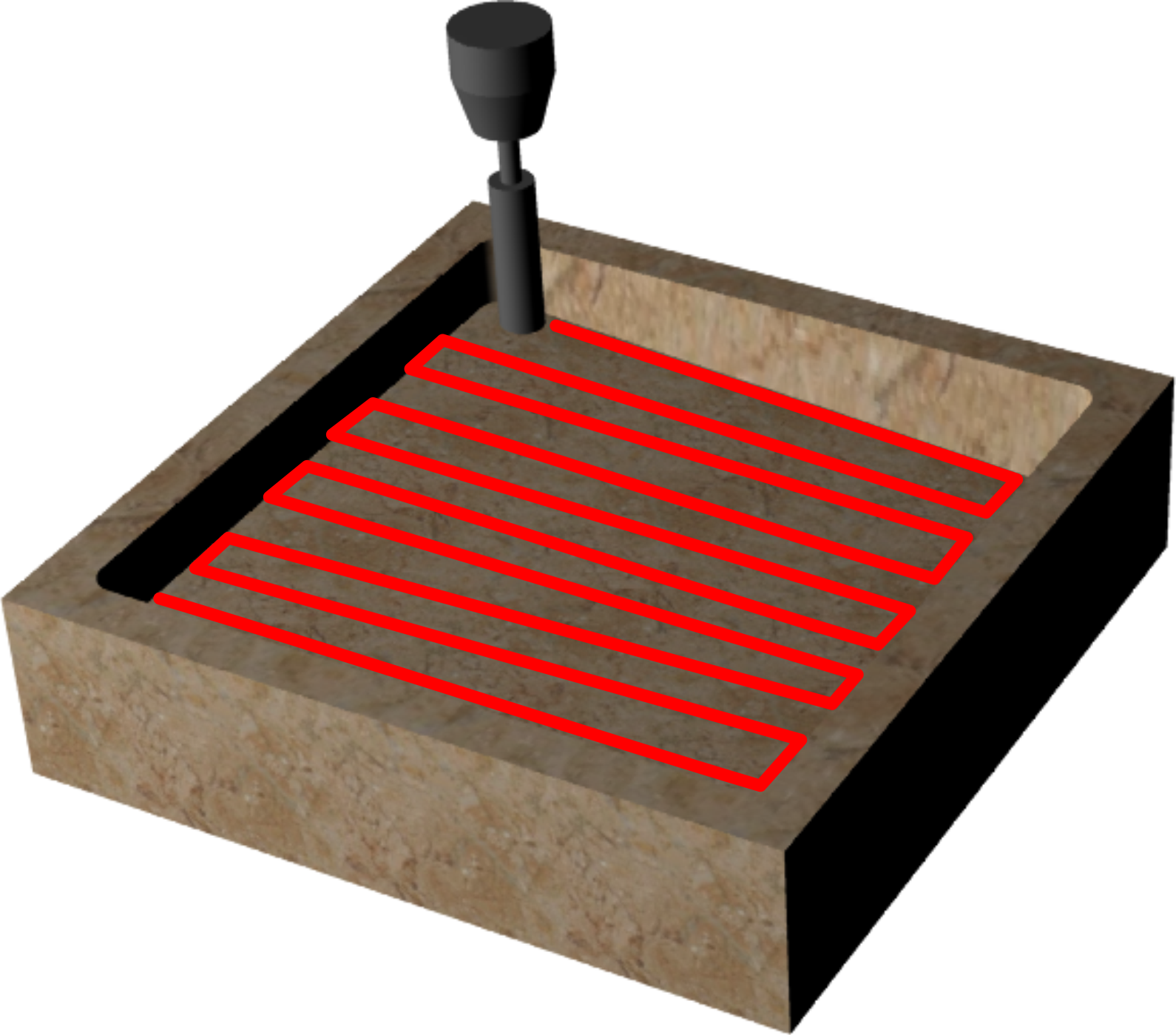
11.3.2.2.2 MILLING - Parametri lavorazione "Svuotatura"

| |  |
|
| |  |
|
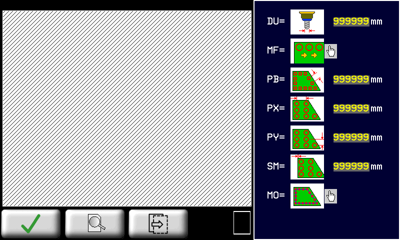
L'area interna di una geometria chiusa viene svuotata tramite foratura. Tale lavorazione calcola la posizione dei fori secondo una modalità impostata con i seguenti parametri.
| |
| |
| |
| DU(Diametro utensile): Impostare il diametro dell'utensile che verrà usato per effettuare la lavorazione. |
| MF(Modo foratura): -  CONTINUO: durante il ciclo automatico i fori vengono realizzati uno dopo l'altro senza attendere la conferma da parte dell'operatore. CONTINUO: durante il ciclo automatico i fori vengono realizzati uno dopo l'altro senza attendere la conferma da parte dell'operatore.-  PAUSA: durante il ciclo automatico la lavorazione attende la conferma con lo START da parte dell'operatore prima di eseguire ogni foro. PAUSA: durante il ciclo automatico la lavorazione attende la conferma con lo START da parte dell'operatore prima di eseguire ogni foro.Toccare immagine per modificare. Quando l'immagine lampeggia premere per cambiare |
|
 | PB(Passo bordo): distanza tra i fori sul bordo. Il parametro viene usato nel caso in cui Modalità = BORDO, BORDO + INT.OR oppure BORDO + INT.V. |
 | PX(Passo X): distanza tra i fori nella direzione X. Il parametro viene usato nel caso in cui Modalità = INTERNO OR., INTERNO VERT., BORDO + INT.OR oppure BORDO + INT.V. |
 | PY(Passo Y): distanza tra i fori nella direzione Y. Il parametro viene usato nel caso in cui Modalità = INTERNO OR., INTERNO VERT., BORDO + INT.OR oppure BORDO + INT.V. |
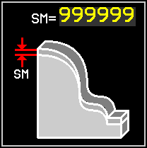
 | SM(Sovrabordo): distanza tra i fori e il bordo della geometria. |
| MO(Modalità): -  BORDO: serie di fori lungo il bordo interno della geometria. BORDO: serie di fori lungo il bordo interno della geometria.-  INTERNO OR.: fori disposti nell'area interna alla geometria secondo delle righe orizzontali. INTERNO OR.: fori disposti nell'area interna alla geometria secondo delle righe orizzontali.-  INTERNO VERT.: fori disposti nell'area interna alla geometria secondo delle colonne verticali. INTERNO VERT.: fori disposti nell'area interna alla geometria secondo delle colonne verticali.-  BORDO + INT. OR.: fori disposti lungo il bordo interno e poi anche nell'area interna della geometria secondo righe orizzontali. BORDO + INT. OR.: fori disposti lungo il bordo interno e poi anche nell'area interna della geometria secondo righe orizzontali.-  BORDO + INT. V.: fori disposti lungo il bordo interno e poi anche nell'area interna della geometria secondo colonne verticali. BORDO + INT. V.: fori disposti lungo il bordo interno e poi anche nell'area interna della geometria secondo colonne verticali.Toccare immagine per modificare. Quando l'immagine lampeggia premere per cambiare |
|
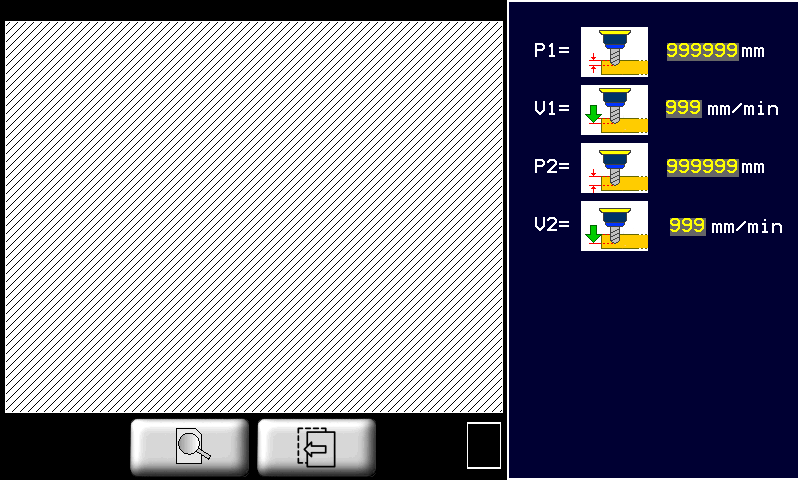
-  P1(Profondità 1) P1(Profondità 1)-  V1(Vel. foratura 1) V1(Vel. foratura 1)-  P2(Profondità 2) P2(Profondità 2)-  V2(Vel. foratura 2) V2(Vel. foratura 2)il foro viene eseguito prima alla profondità 1 con la velocità 1, poi la foratura continua fino alla profondità 2. La velocità viene incrementata gradualmente fino alla velocità 2. |
|
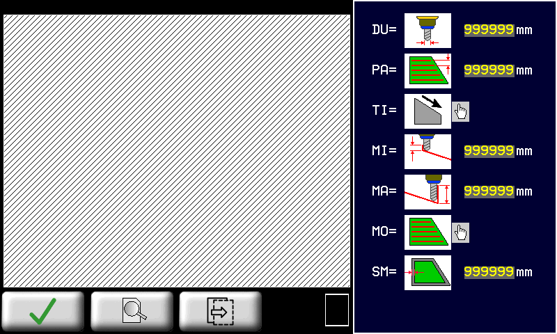
11.3.2.2.3 POCKETING - Parametri lavorazione "Tasca"
| |  |
|
| |  |
|
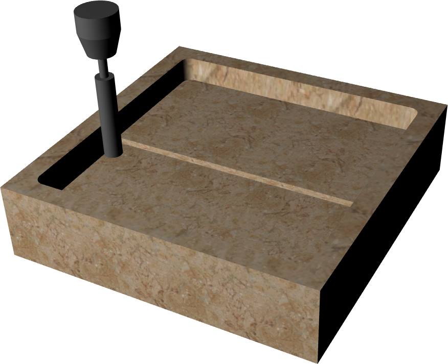
L'area interna di una geometria chiusa viene fresata per realizzare una tasca. Il fondo della tasca può essere inclinato secondo una direzione impostata.
| |
| |
| |
| DU(Diametro utensile): Impostare il diametro dell'utensile che verrà usato per effettuare la lavorazione. |
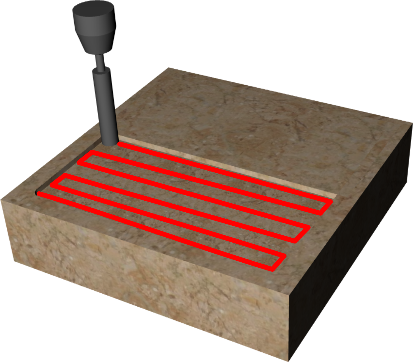
 | PA(Passo): distanza tra una fresatura e la successiva. Se la MO (Modalità) - ORIZZONTALE è la distanza lungo Y, - VERTICALE è la distanza lungo X, - SPIRALE è la distanza tra i percorsi concentrici. |
| TI(Tipologia): è il tipo di inclinazione che si vuole dare al fondo della tasca. - la profondità aumenta con X crescenti.- la profondità aumenta con X decrescenti.- la profondità aumenta con Y decrescenti.- la profondità aumenta con Y crescenti.Toccare immagine per modificare. Quando l'immagine lampeggia premere per cambiare |
|
| MI(Minima Profondità): è la profondità più bassa ottenuta durante il taglio. |
| MA(Massima Profondità): è la profondità più alta ottenuta durante il taglio. |
| MO(Modalità): - ORIZZONTALE: la tasca viene realizzata con fresature lungo la direzione X.-  VERTICALE: la tasca viene realizzata con fresature lungo la direzione Y. VERTICALE: la tasca viene realizzata con fresature lungo la direzione Y. -  SPIRALE: la tasca viene realizzata con fresature concentriche. SPIRALE: la tasca viene realizzata con fresature concentriche.Toccare immagine per modificare. Quando l'immagine lampeggia premere per cambiare |
|
 | SM(Sovrabordo): è la quantità di materiale lasciato dall'utensile sul bordo interno alla geometria. |
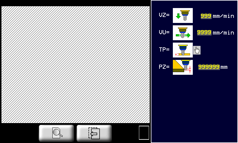
| VZ(Vel. Z-): E' la velocità con cui l'utensile viene mosso nella direzione Z- (verso il basso). |
| VU(Velocità utensile): Impostare una velocità adeguata al tipo di lavorazione da effettuare. |
| TP(Tipo passata): - SINGOLA: la profondità impostata viene raggiunta con un'unica passata dell'utensile sul percorso calcolato.- MULTIPLA: la profondità impostata viene raggiunta attraverso una ripetizione del percorso a profondità via via maggiori.L'inclinazione del fondo viene comunque garantita in entrambi i casi. Toccare immagine per modificare. Quando l'immagine lampeggia premere per cambiare |
|
| Passo Z: nel caso di Tipo passata = Multipla, esso è l'incremento della profondità di Z tra una passata e la successiva. |
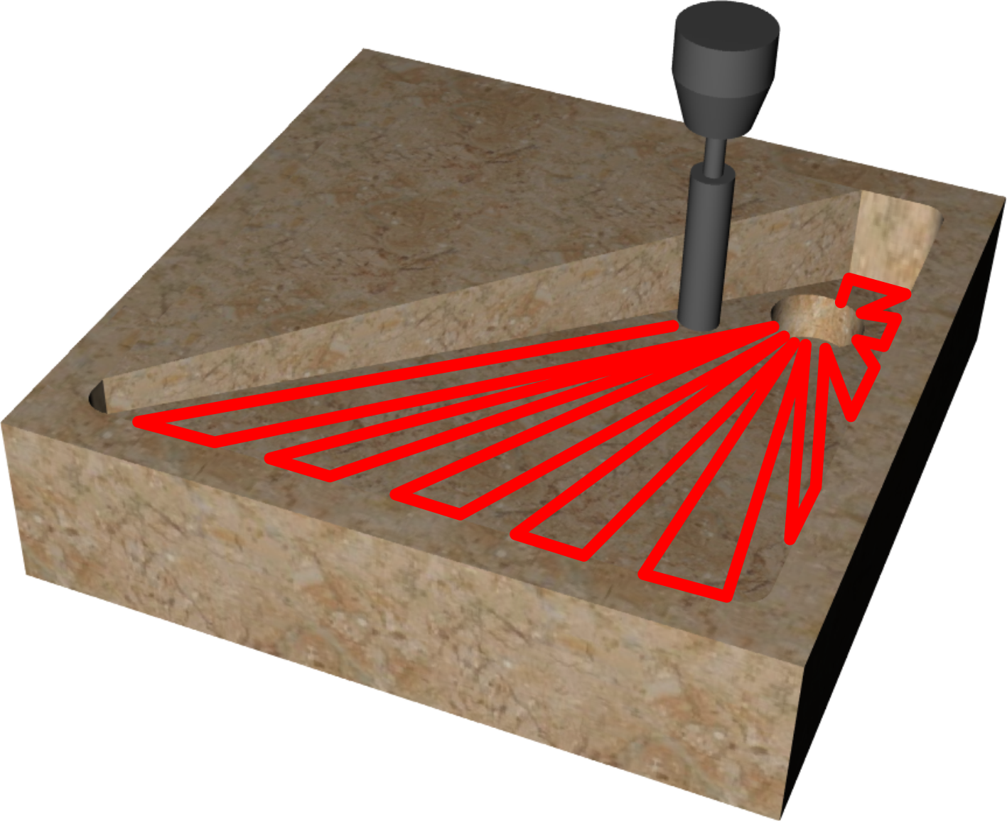
11.3.2.2.4 POCKETING 3D - Parametri lavorazione "Rastrematura"
| |  |
|
| |  |
|
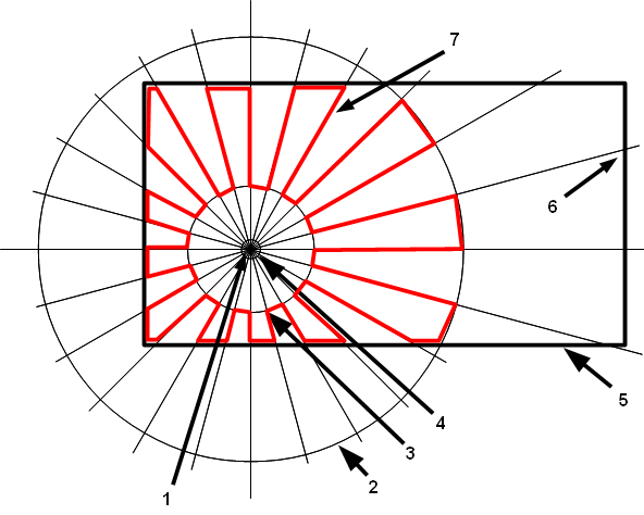
L'area interna di una geometria chiusa viene fresata per inclinare il fondo della tasca verso un punto specificato chiamato centro dello scarico. I movimenti dell'utensile saranno radiali verso il centro dello scarico.
| Lavorazione Tasca3D applicata ad una geometria rettangolare | |
|---|---|
 |
|
| 1 | Profondità nel centro |
| 2 | Raggio esterno |
| 3 | Raggio interno |
| 4 | Raggio scarico |
| 5 | Geometria chiusa |
| 6 | Profondità sul bordo |
| 7 | Percorso utensile calcolato |
| |
| |
| |
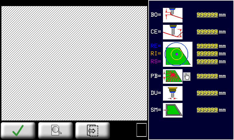
| BO(Prof. bordo): profondità applicata quando l'utensile si trova sul bordo interno della geometria. |
 | CE(Prof. centro): ipotetica profondità se l'utensile si trovasse nel centro. Le due profondità sul bordo e nel centro determinano l'inclinazione di ogni singola fresatura radiale. |
 | - RE(Rag. esterno): raggio della circonferenza di riferimento esterna. - RI(Rag. interno): raggio della circonferenza di riferimento interna. - RS(Rag. scarico): raggio dello scarico. Circonferenza su cui viene applicata la profondità del centro. |
| Modalità: -  PB = PASSO SU BORDO. Le fresature radiali calcolate in modo che gli incroci con il bordo della circonferenza siano ad una distanza tra loro pari al passo sul bordo. PB = PASSO SU BORDO. Le fresature radiali calcolate in modo che gli incroci con il bordo della circonferenza siano ad una distanza tra loro pari al passo sul bordo.-  PR = PASSO R. EST.. Le fresature radiali vengono calcolate in modo che gli incroci con la circonferenza esterna siano ad una tra loro pari al passo r. est. PR = PASSO R. EST.. Le fresature radiali vengono calcolate in modo che gli incroci con la circonferenza esterna siano ad una tra loro pari al passo r. est. |
|
| DU(Diametro utensile): Impostare il diametro dell'utensile che verrà usato per effettuare la lavorazione. |
| SM(Sovrabordo): è la quantità di materiale lasciato dall'utensile sul bordo interno alla geometria. |
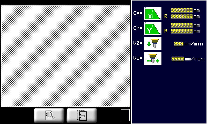
  | CX e CY (Centro (X, Y)): sono le coordinate X, Y del centro dello scarico. Possono essere inserite riferite al sistema di riferimento del pezzo oppure al sistema di riferimento della geometria stessa. |
| VZ(Vel. Z-): E' la velocità con cui l'utensile viene mosso nella direzione Z- (verso il basso). |
| VU(Velocità utensile): Impostare una velocità adeguata al tipo di lavorazione da effettuare. |
11.3.2.2.5 SAW CUT - Parametri di lavorazione taglio
| | 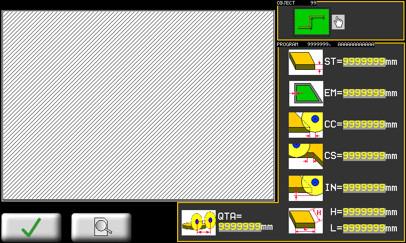 |
| |
| |
  | LU(Lato Utensile) : Determina la posizione del centro lama rispetto alla geometria. Per geometrie aperte si selezionerà se la lama sarà a sinistra o a destra della geometria. Con geometrie chiuse il parametro prende il significato di lavorazione interna o esterna alla geometria. Premere sull'immagine per cambiare |
 | ST |
| EM |
 | CC |
 | CS |
 | IN |
 | - H - L |
 | QTA |
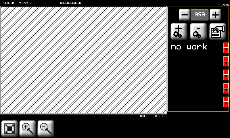
This is the starting point page to manage user programs.
You can:
-
View programs list.
-
Select a program in the list touching related description.
-
Walk forward and backward from program list using page left/right buttons.
-
Get a graphical snapshot of selected program geometries.
-
Filter program list using a short string to match and/or between program type.
-
Put quickly in run the selected program using the Program Execution button.
11.3.3 New program taglio poligoni
| | |
||
| | | |
|
|
|||
| Import from Memory Card |
| Save a program |
| | See chapter Milling drawing editor |
| | See chapter SAW CUT - Parametri di lavorazione taglio |
11.3.4 Program's List Filters
 Using the program's list filters is possible to get quickly the desired program, rather than scroll entire available list.
The system permit two type of filtering which can be combined each other:
-
Filter on program description
-
Filter on program type
You can use the field „Filter“ to enter 1 or 2 ASCII chars which are part of description that are to search.
For example to search any program which contains the sub-string „MA“ just enter MA in „Filter“ field.
To activate a new filter is necessary to DISABLE and ENABLE filtering using related button.
Any changes to „Filter“ and „Type“ field require switch of filter button to be acquired.
With „Type“ is possible to filter all programs of same type:
| Type | Description |
|---|---|
| 0 | Show any program |
| 1 | Show only tagli sagomati/profilatura programs |
| 2 | Show only fresatura programs |
| 3 | Show only taglio poligoni programs |
Combine two filter settings to get a better result.
11.4 Program execution
11.4.1 Program type 0 (Profili dritti)
 | 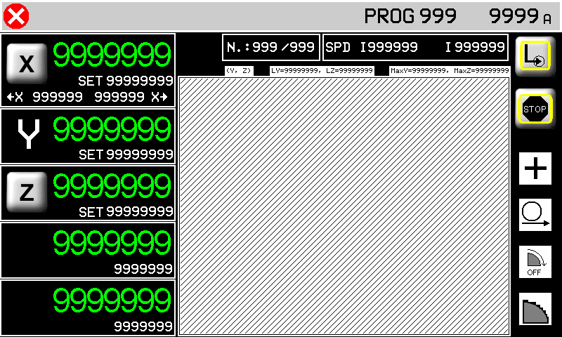 |
 |
|
| 1 | Solo se abilitato in setup, tramite parametro „abilita profilo 90°“ |
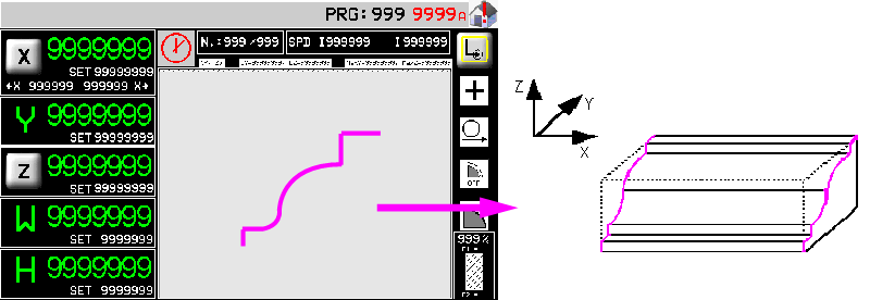
Una volta dato lo start verranno realizzati in successione tutti i tagli con un'unica passata (marmo) oppure ad incrementi successivi (granito) in accordo con i parametri impostati in precedenza. La successione dei tagli compone la sgrossatura del profilo. L'asse X si muoverà sempre tra le due quote autoapprese che dovranno essere esterne al blocco da lavorare.
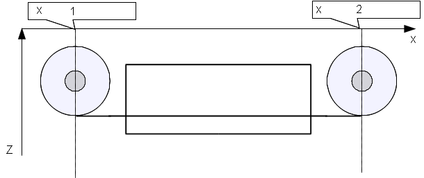 |
|
| 1 | minima autoappresa |
| 2 | massima autoappresa |
A questo punto può essere eseguita la finitura se il selettore della finitura è stato impostato su CONTINUA (se impostato su OFF la finitura verrà saltata, se impostato su SOLO la finitura verrà eseguita subito, senza eseguire la sgrossatura).
Per eseguire l'operazione di finitura la lama si porta sulla quota di X autoappresa minima + quota di correzione e quindi esegue una serie di passate in interpolazione YZ in accordo con i parametri per la finitura impostati. La finitura finisce quando si arriva alla quota X autoappresa massima - quota di correzione (vedi esempio).
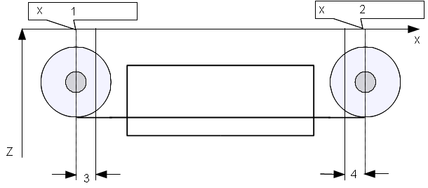 |
|
| 1 | minima autoappresa |
| 2 | massima autoappresa |
| 3 | quota di correzione + |
| 4 | quota di correzione - |
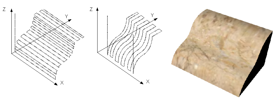 |
| Sgrossatura, finitura e profilo risultante |
Nel dare start al ciclo automatico verrà richiesta un'operazione di azzeramento delle quote degli assi.
11.4.2 Program type 0 (Profili sagomati)
| | 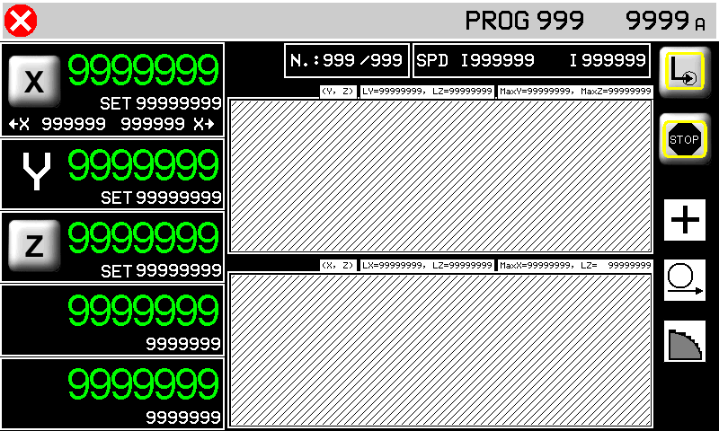 |
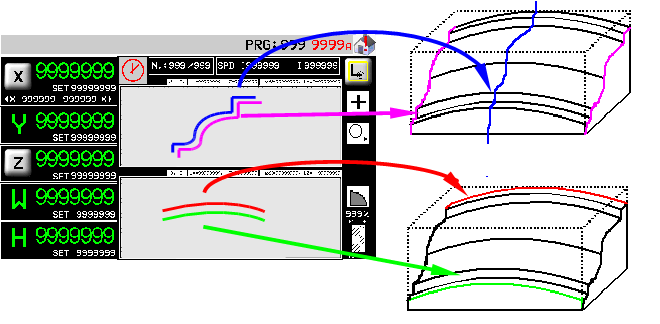
I tagli vengono realizzati in successione con un'unica passata (marmo) oppure ad incrementi successivi (granito) in accordo con i parametri impostati in precedenza. La successione dei tagli compone la sgrossatura del profilo. I tagli vengono eseguiti partendo dalla quota X autoappresa minima aggiungendo due tratti orizzontali lunghi come il raggio della lama, prima e dopo il profilo disegnato.
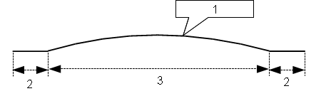 |
|
| 1 | profilo disegnato |
| 2 | raggio lama |
| 3 | larghezza del profilo |
Si potranno presentare quindi due casi:
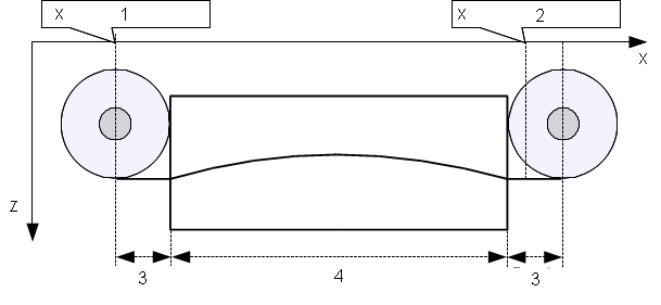 |
|
| 1 | minima autoappresa |
| 2 | massima autoappresa |
| 3 | raggio lama |
| 4 | larghezza del profilo |
In questo caso la larghezza del profilo sommato al diametro della lama è maggiore della distanza tra le due quote di X autoapprese. Come si vede dalla figura, il taglio parte alla quota minima autoappresa e viene eseguito completamente fino a superare la quota X massima autoappresa.
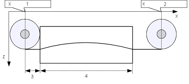 |
|
| 1 | minima autoappresa |
| 2 | massima autoappresa |
| 3 | raggio lama |
| 4 | larghezza del profilo |
In questo caso la larghezza del profilo sommato al diametro della lama è minore della distanza tra le due quote di X autoapprese. Come si vede dalla figura, il taglio parte alla quota minima autoappresa ,mentre il tratto orizzontale finale viene prolungato fino a portare il centro della lama sulla quota X autoappresa massima.
Il processo di finitura non è previsto per le lavorazioni di taglio curvilineo.
Questa schermata spiega che la lama deve essere portata a sfioro del blocco (come rappresentato), prima di dare l' OK per l'azzeramento delle quote degli assi.
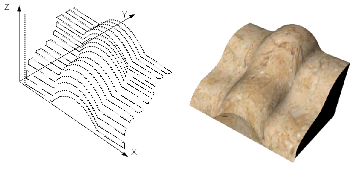 |
| Sgrossatura e profilo risultante |
11.4.3 Program type 1 or 2 (Profili sagomati)
| | 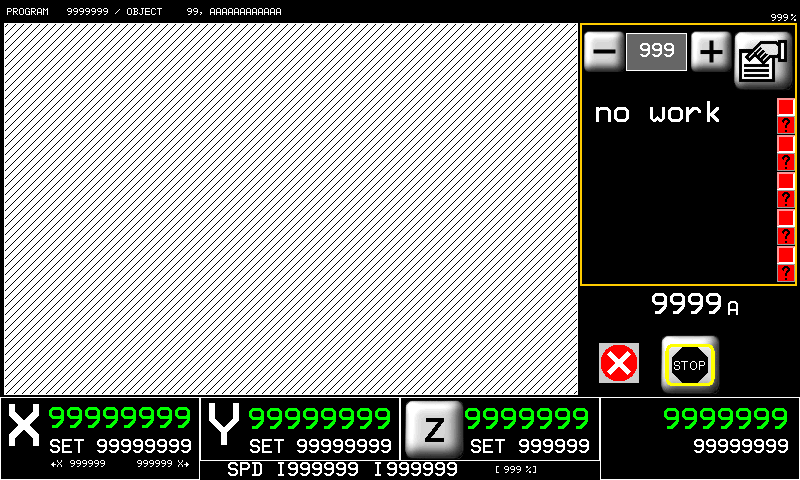 |
Nella pagina di esecuzione 2D è possibile lanciare l'esecuzione di un programma 2D. Nella lista di lavorazioni sono evidenziate a gruppi di 5 in un menu scorrevole le singole operazioni che compongono il programma. Durante l'esecuzione verrò visualizzata l'esecuzione della lavorazione in maniera simile a quanto ottenuto in fase di programmazione.
Nel dare start al ciclo automatico verrà richiesta un'operazione di azzeramento delle quote degli assi.
12. Manual/Semiautomatic
 | 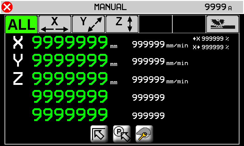 |
 | |
 | |
 |
 to view the 5 axis positions (distance from zero) and speeds
 | 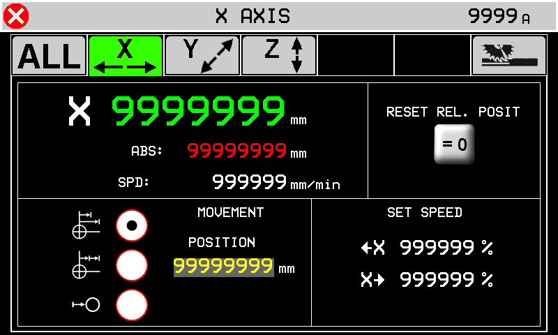 |
 | 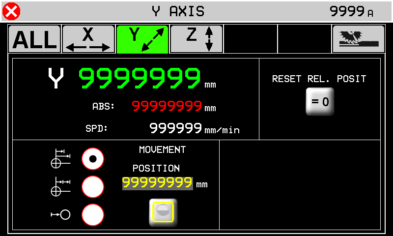 |
 | 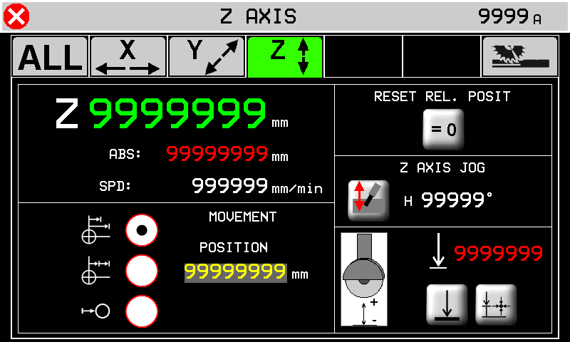 |
 | 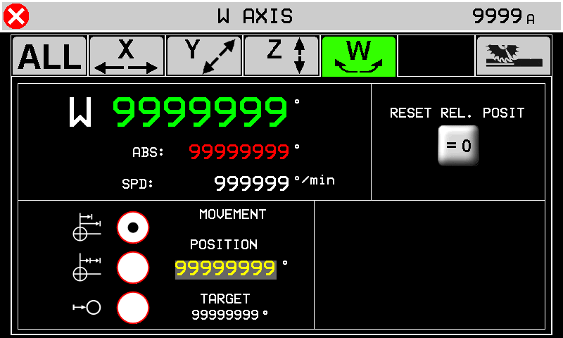 |
 | 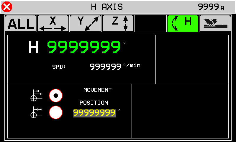 |
Here you can move the axis as the base page and further you can start a moving to a quota.
| - - - |
|
 | Reset the axis position and selflearn a new zero position |
  | Disk thickness correction ON-OFF. |
 | The minimun safe position is the setup quota. |
 | The minimun safe position is the selflearn quota. Press to selflearn Z position for the minimun safe quota. |
 | |
 | |
 | |
| Se H ha l'encoder abilitato | 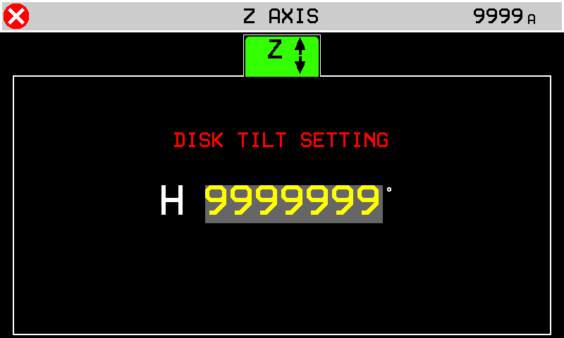 |
 | 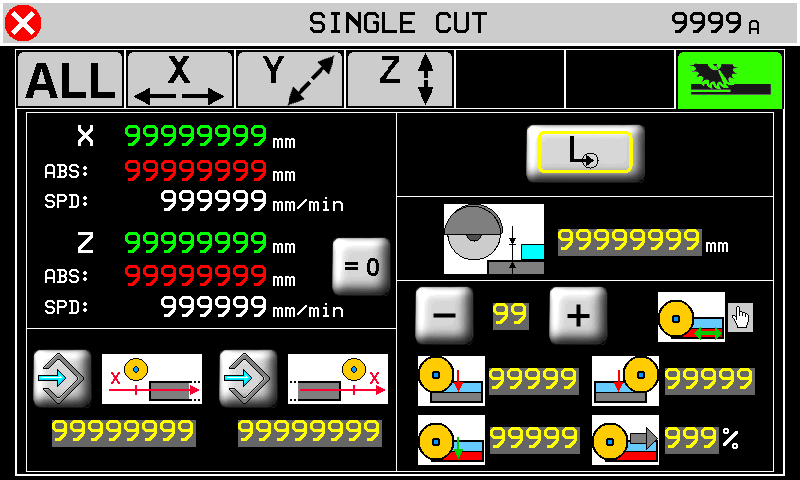 |
Single cut screen:
| Press to selflearn the quotas. | ||
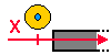 | X-Axis position of start cut. | 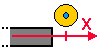 | X-Axis position of end cut. |
| Single cut. | | Step cuts with multiple depth increases. |
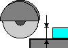 | Cut depth position. | ||
 99 99  | Material type. Up to 10 materials can be stored. | ||
| Depth increase at start cut. | | Depth increase at end |
| Final depth increase to complete the cut. | | Speed during the final depth cut. |
  | Descrivere il pulsante Press for change |
||
13. Machine Data
 | 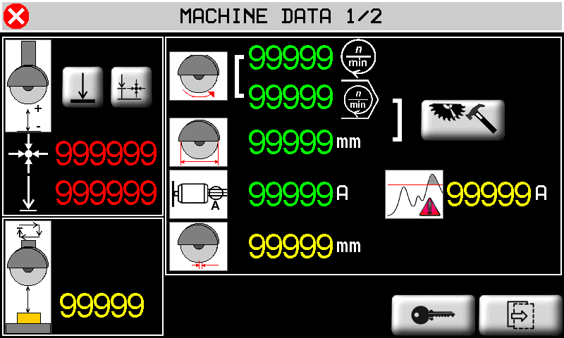 |
|
| | 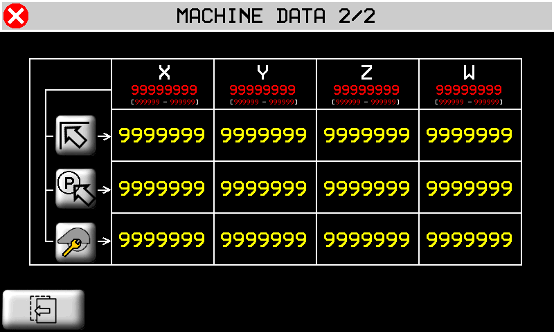 |
|
| | Previus and next page |
 | |
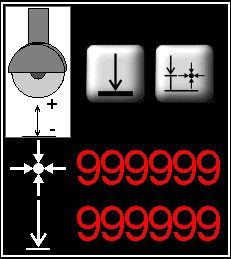 | |
 | |
 | |
 | Blade diameter |
 | |
 | Blade thickness |
 | |
| | |
| | |
| |
 | 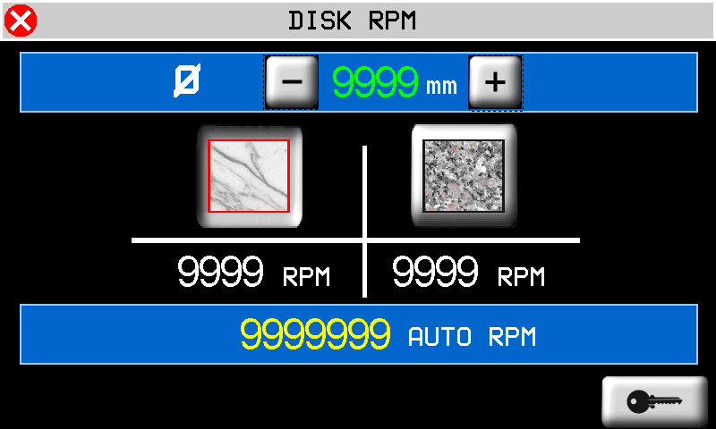 |
 | |
 | Marble |
 | Granite |
 |
 | 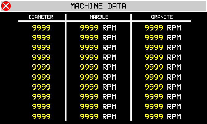 |
14. ISO G codes
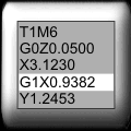 | 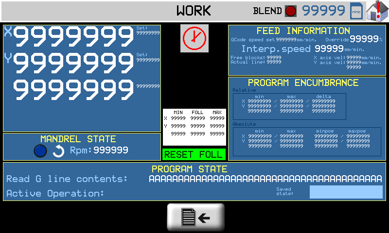 |
N.B. Optional accessory requiring QEM Isomanager (see specific manual insert link )
The ISO code is processed by performing a tool path created on a CAD/CAM, which creates a list of G code instructions that are then converted into a .hex file by the Qem Isomanager software.
The .hex file is then downloaded onto the controller by Ethernet, Modem or SD card.
If an SD card is used, the .hex file must be renamed with a number from 0 to 999999. (file name: 1.hex, 2.hex…)
The Program State box:
| Execution Mode | set one of the following modes: 1: read from MMC read file from a Memory card 2: read from remote read file from the PC connection 3: store in MMC only save file from PC to Memory card |
| MMC program number | the .hex file number in the MMC/SD card. |
| Read status | the percentage progress of reading the file on MMC/SD card. |
| Block Executed | ISO instructions executed. |
| G code actual line num. | the actual ISO instruction number. |
| G code actual line | the actual ISO instruction. |
Press  for program setting
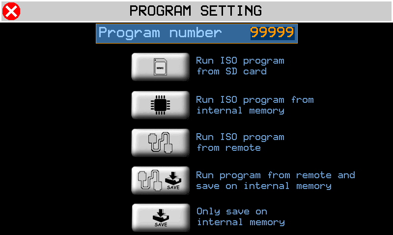
 | Execute ISO from MMC/SD |
 | Execute ISO from internal memory |
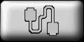 | Execute ISO from remote |
 | Execute from remote and store in internal memory |
 | Only store in internal memory |
14.0.0.1 Center
Press 
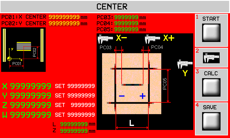
| START |
| CALC |
| SALVA |
Questa pagina offre uno strumento per poter correggere le quote X e Y della posizione del centro banco.
Una volta visualizzata questa pagina le coordinate X e Y del centro banco verranno copiate rispettivamente in PC01 e PC02.
Le fasi da seguire sono le seguenti:
-
Selezionare la modalità manuale.
-
Assicurarsi che l'asse Z sia stato azzerato sulla superficie da incidere. Eventualmente accedere alla pagina di manuale per farlo.
-
Avviare il disco e attendere che sia arrivato in velocità.
-
Toccare il tasto START sul display e lasciar eseguire l'incisione dei 5 tagli come mostrato in figura. Le incisioni dei lati del quadrato verranno eseguite alla profondità specificata nel parametro Z. L'incisione centrale verrà eseguita a profondità fissa di 5 mm.
-
Una volta eseguita l'incisione si devono eseguire le 3 misure indicate e si devono scrivere nei parametri PC03, PC04, PC05.
-
A questo punto si può premere il tasto CALC sul display per eseguire le correzioni. Si noteranno i valori PC01 e PC02 cambiare. Il tasto CALC può essere usato una sola volta e quindi se si vogliono modificare le misure inserite e ricalcolare le correzioni, bisogna uscire dalla pagina e rientrare.
-
Se si accetta la correzione, allora si devono salvare i nuovi valori premendo il tasto SAVE. Si uscirà automaticamente dalla pagina.
-
A questo punto è possibile rientrare in questa pagina ed eseguire ancora l'incisione (punti 1, 2 e 3) per verificare che PC03 e PC04 siano tra loro uguali e PC05 sia pari a L mm.
| Nome parametro | Unità di misura | Default | Range | Descrizione |
|---|---|---|---|---|
| PC01 : X CENTER | mm | 1699.10 | 0÷999999.99 | Copia della coordinata X del centro del banco. |
| PC02 : Y CENTER | mm | 1765.60 | 0÷999999.99 | Copia della coordinata Y del centro del banco. |
| PC03 : | mm | 0.00 | -999.99 ÷ 999.99 | Misure come da disegno per la correzione della coordinata X del centro. |
| PC04 : | mm | 0.00 | -999.99 ÷ 999.99 | |
| PC05 : | mm | 0.00 | 0÷9999.99 | Misure come da disegno per la correzione della coordinata Y del centro. |
| L: | mm | 200.00 | 0÷999999.99 | Lato L dell'incisione praticata. |
| Z: | mm | 5.00 | 0÷999999.99 | Profondità del taglio dei lati |
Press to exit
14.1 Enable
Premere il pulsante nell'area 1.
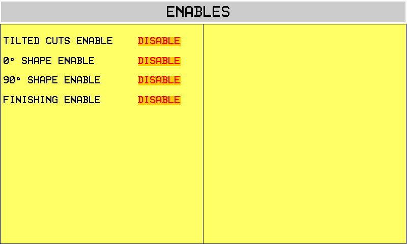
15. Alarms
 in any screen in any screen | 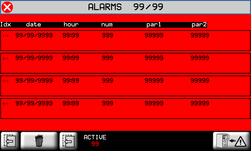 |
 to cancel the alarms.
Alarms block the machine operation.
| Alarm | Cause | Solution |
|---|---|---|
| Emergency | Manual emergency stop | - |
| Y limit switch backward | Y-axis at minimum LS | - |
| Y limit switch forward | Y-axis at maximum LS | - |
| Z limit switch backward | Z-axis at minimum LS | - |
| Z limit switch forward | Z-axis at maximum LS | - |
| X limit switch backward | X-axis at minimum LS | - |
| X limit switch forward | X-axis at maximum LS | - |
| H limit switch backward | H-axis at minimum LS | - |
| H limit switch forward | H-axis at maximum LS | - |
| Blade not running | Disk must be running in automatic cyle | - |
| Water pressure | No cooling water | The water valve shut |
| Blade motor overcurrent | The disk motor current absorption is over the threshold | - |
| Z Following error | The axis follow error is over the maximum threshold | - |
| Y Following error | - | |
| X Following error | - | |
| Interpolation fault | There is an error during the interpolation of the axes. | One of the axes has gone over the maximum position. |
| Thermic fault | Overload of drivers tripped | - |
| Driver is fault | Fault in one of the axis drivers | - |
| X encoder fault | The encoder of the axis does not work properly | - |
| Y encoder fault | - | |
| Z encoder fault | - | |
| W sensor missing | The low table sensor could be disconnected. | - |
| Y Axis out of tolerance | The axis positioning out of set tolerance. | Control the axis setup parameters |
| Z Axis out of tolerance | ||
| W Axis out of tolerance | ||
| H Axis out of tolerance | ||
| CAN module - data error | CAN module is in error | Check CAN comunication or the cable |
| CAN module - no comunication | CAN module does't respond | |
| MMC/SD not present | Error during upload/download data with MMC/SD | Check the MMC/SD support, check the correct procedure |
| MMC/SD error update | ||
| MMC/SD file not open | ||
| MMC/SD file not create | ||
| MMC/SD error write | ||
| MMC/SD error seek | ||
| MMC/SD error read | ||
| MMC/SD error read seek | ||
| MMC/SD error read format | ||
| MMC/SD error record | ||
| MMC/SD error delete | ||
| MMC/SD error max retry | ||
| MMC/SD undefined error | ||
| INT: motion mode not defined | Error from interpolation interpreter | - |
| INT: exact path mode not supported | ||
| INT: invalid istruction | ||
| INT: invalid version | ||
| INT: invalid release | ||
| INT: spindle management | ||
| INT: change tool management | ||
| Mechanical components activation error | Error from interpolation execution | |
| Device INTERP writing error | ||
| Device INTERP starting error |
15.1 Alarm history
 | 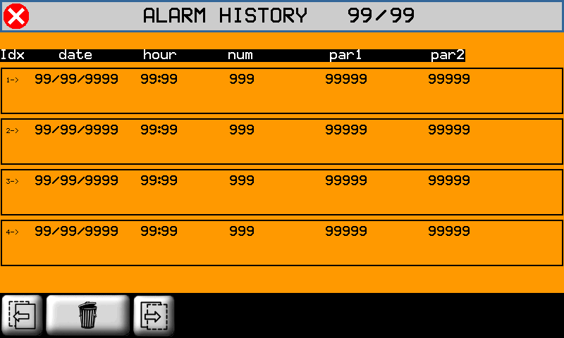 |
To cancel the history, press
15.2 Warning Messages
Messages do not block the machine operation.
| Messagge | Cause | Solution |
|---|---|---|
| WAIT PLEASE… | A calculation is in course. | - |
| PATH ERROR | An error has been found in the path settings, before the process. | Control that the path is not too long |
| ERR: BLADE SLOPED | The inclination of the blade and the tool is not correct for the work cycle. | The blade or the tool inclination must be corrected |
| WORK DONE | The automatic cycle is completed without problems. | - |
| X POSITION NOT OK | The position of X is not correct. | It is external to the self-learn positions of the LS. |
| BATTERY DOWN | The battery of the controller is flat or has a low charge. | See the installation and maintenance manual for the battery change instructions. |
| EXECUTE HOMING | The Homing procedure has not be performed. | Perform the homing procedure. |