Table of Contents
P1K31FR30-001 - 3 axis bridge saw: Installation Manual
| Document | P1K31FR30-001 | ||
|---|---|---|---|
| Description | User manual | ||
| Drawn up | Riccardo Furlato | ||
| Approved | Draft | ||
| Link: | http://www.qem.eu/doku/doku.php/en/strumenti/qmoveplus/j1k31/mdu_p1k31fr30-001/funzionamento | ||
| Languages | English | ||
| Release | Description | Notes | Date |
| 01 | New Manual | 26/05/14 | |
Table of Contents
All rights reserved on this manual. No part of this document can be copied or reproduced in any form without prior written authorisation. QEM does not insure or guarantee its contents and explicitly declines all liability related to the guarantee of its suitability for any purpose. The information in this document can be changed without notice. QEM shall not be held liable for any error or omission in this document. QEM® is a registered trademark.Microsoft® and MS-DOS® are registered trademarks and Windows® is a trademark of Microsoft Corporation.
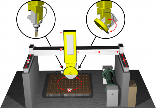
1. Hardware J1-K31-FR30

1.1 Function Keys and LEDs
| Key | Icon | Function | Led | Key | Icon | Function | Led |
|---|---|---|---|---|---|---|---|
| F1…F3 | Not Used | ||||||
| F4 | | Enclosures | Enclosure open status | F5 | Not used | ||
| F6 | | Y Laser ON/OFF | Laser status | F7 | | X Laser ON/OFF | Laser status |
| F8 | | Water ON/OFF | Water status | F9 | | Alarm = ON | - |
| F10 | | Quit or prolonged MAIN | - | F11 | | Semiautomatic = ON | Semiautomatic status |
| F12 | | Table UP | Table up | F13 | | Table DOWN | Table Down |
| F14 | | Table Rotation Anticlockwise | - | F15 | | Table Rotation Clockwise | - |
| F16 | | Disk ON/OFF | Blink is starting, On is started | F17 | | Mill ON/OFF | Blink is starting, On is started |
| - - - - - | - - - - - - - - | - - - - - - - - - - - - - - - - - - - - - - - - - | - - - - - - - - - - | - - - - - | - - - - - - - - | - - - - - - - - - - - - - - - - - - - - - - - - - | |
1.2 Symbols and Buttons
| Button | Description | ———————– | Top Bar Symbol | Description |
|---|---|---|---|---|
| | Press to confirm | | Manual | |
| | Select | | Emergency | |
 | Previous screen | | Automatic | |
 | Next screen | | Function mode | |
 | Reserved Area | | Not initialized | |
| | Open file on SD card | | Setup Locked/Unlocked | |
| | Save | |||
 | Work preview | |||
 | Yellow settings can be changed | |||
| - - - - - - - - - - - - - | - - - - - - - - - - - - - - - - - - - - | - - - - - - - - - - - - - - - - - - | - - - - - - - - - - - - - | - - - - - - - - - - - - - - - - - - - - |
1.3 Startup
| START | | OR  to bypass |
 |
||
| HOMING |  | OR to bypass |
| |
||
| MAIN MENU |  | |
2. SETUP
  | | |||
 |  |
|||
 PASSWORD 462 |  |
|||
 | SETUP parameters | ||
 | Axis calibration | ||
 | Load default parameters | ||
| | Diagnostic | | Table Center |
| | Unlock Setup Area No password for 24 hours | | Lock Setup Area Password access only |
 | Set system Date and Time | ||
| - - - - - - - - - - - - - - - | - - - - - - - - - - - - - - - - - - - - - | - - - - - - - - - - - - - - - | - - - - - - - - - - - - - - - - - - - - - |
2.1 Load Default parameters
| | | |||
| | |
|||
| PASSWORD 462 | |
|||
| |
||||
 |
||||
| YES Load Default | NO To Cancel |
|||
3. SETUP parameters
| | |
|||
| | |
|||
| PASSWORD462 | |
|||
| |
||||
 |
||||
3.1 General Parameters
GEN  | |
| Parameter | U.M. | Default | Range | Description |
|---|---|---|---|---|
| PG-01 : DECIMAL POINT X/Y/Z | - | 1 | 0 - 2 | Number of decimal points for X, Y and Z axis positions For inches the position is shown with “DECIMAL POINT + 1”. |
| PG-02 : DECIMAL POINT W | - | 2 | 0 - 2 | Number of decimal point for W axis position |
| PG-03 : DECIMAL POINT H | - | 2 | 0 - 2 | Number of decimal point for H axis position |
| PG-04 : MAX RPM DISK | rpm | 2480 | 0 - 3000 | Maximum setting of disk rpm. |
| PG-05 : LASER TIME | s | 30 | 0 - 9999 | If > 0 the laser is automatic with Y axis movement. When axis stops laser powers off after this time. If = 0 the laser can only be activated by F7 func key |
| PG-06 : WATER CONTROL TIME | s | 5 | 0 - 9999 | If there is a water fault, the alarm is given after this time. |
| PG-07 : DISABLE WATER CONTROL | - | 0 | 0 - 1 | 0: water control enabled; 1: water control disabled. |
| PG-08 : BUZZER HMI | - | 0 | 0 - 1 | 0: buzzer enabled 1: buzzer disabled. |
| PG-09 : ALARM SOUND TIME | s | 10 | 0 - 999 | Time the Alarm sounds when the machine is in an alarm state. |
| PG-10 : UNIT MEASURE | - | 0 | 0 - 1 | 0: mm 1: inches All setup parameters are given in mm. |
| PG-11 : LANGUAGE | - | 1 | 1 - 2 | 1: ENGLISH 2: ITALIAN |
| PG-12 : HOMING MODE | - | 1 | 0 - 3 | 0:Homing necessary to unlock all other operations; 1:Homing not necessary, all functions are unlocked; 2 = Homing necessary for automatic cycle, without only manual movements are possible 3:Homing necessary to unlock all other operations. The Homing starts automatically. |
| PG-13 : Not Used | ||||
| PG-14 : MIN ANALOG INPUT READING | bit | 5 | 0 - 1000 | If > = all analog inputs are forced to zero. |
| PG-15 : INTERPOLATION SPEED OVERRIDE | - | 0 | 0 - 1 | 0: override applied to calculated speed 1: override applied to set speed |
| PG-16 : CORNER TYPE | - | 0 | 0 - 1 | 0: corner with smoothed center 1: Not Used |
| PG-17 : CORNER ERROR | mm | 0.5 | 0 - 999.9 | Distance error from corner start and center. |
| PG-18 : RAPID SPEED | mm/min | 1000 | 0 - 9999 | Feedrate of straight traverse during work execution or G code execution |
| PG-19 : MAX CURRENT | A | 100.0 | 0 - 100.0 | Maximum analogic input for spindle current. |
| PG-20 : SPINDLE SPEED OK DELAY | s | 0 | 0 - 99.999 | 0: machine waits input I 15 for spindle speed ok >0: machine only waits delay time |
| PG-21 : MILL MAX RPM | rpm | 3000 | 0 - 3000 | Maximum mill rpm. |
| PG-22 : HOMING SEQUENCE | - | 0 | 0 - 1 | 0: single axis homing; 1: after Z axis homing, the others are together. |
3.2 X, Y, Z axis setup
| X SETUP  Y SETUP  Z SETUP  | |
| Parameter | U.M. | Default | Range | Description |
|---|---|---|---|---|
| PX-01 : MEASURE | mm | 0.1 | 0 - 99999.9 | Distance, in unit measure, of the axis movement to obtain the pulses set in PX-01. |
| PX-02 : PULSE | - | 1 | 0 - 999999 | Encoder pulses for the distance set in PX-1. PX-01/PX-02 is the axis resolution. It must be 1 ~ 0.000935. |
| PX-03 : TOLERANCE | mm | 0.50 | 0 - 99.99 | Distance around target position. If an axis stops inside this distance, the positioning is correct. |
| PX-04 : ENABLE TIME | s | 0.200 | 0 - 9.999 | Enable time before axis starts moving. |
| PX-05 : DISABLE TIME | s | 0.200 | 0 - 9.999 | Disable time after axis stops. |
| PX-06 : ENABLE AXIS OUTPUT | - | 1 | 0 - 1 | Enable axis output mode. 0: output ON before axis movement and OFF after axis stop in times set in PX-04 and PX-05. 1: output always ON when machine is not in alarm state. |
| PX-07 : JOG FUNCTION | - | 1 | 0 - 1 | Jog function type. 0: In jog, axis control is open loop. 1: In jog, axis control is closed loop. |
| PX-08 : MAXIMUM QUOTA | mm | 99999.9 | -99999.9 - 99999.9 | Maximum quota for the axis. Software limit switch.(x) |
| PX-09 : MINIMUM QUOTA | mm | -99999.9 | -99999.9 - 99999.9 | Minimum quota for the axis. Software limit switch.(x) |
| PX-10 : HOMING OFFSET | mm | 0 | -99999.9 - 99999.9 | Set position at the end of homing procedure.(x) |
| PX-11 : HOMING TYPE | - | 0 | 0 - 3 | 0: Axis goes to homing sensor, inverts movement and goes to PX-10. 1: Axis goes to homing sensor, inverts movement and sets PX-10 position as encoder zero signal. 2: Axis homing without movement. Set PX-10 position on homing sensor signal. 3: homing disabled. |
| PX-12 : HOMING DIRECTION | - | 0 | 0 - 1 | 0:forward; 1:backward. |
| PX-13 : HOMING FAST SPEED | mm/min | 10 | 0 - 9999999 | Homing sensor search speed. |
| PX-14 : HOMING SLOW SPEED | mm/min | 10 | 0 - 9999999 | Axis speed after inversion in homing. |
| PX-15 : HOMING SEQUENCE ENABLE | - | 1 | 0 - 1 | 0: Axis not included in automatic homing sequence. 1: Axis included in automatic homing sequence. |
| PX-16 : ACCELERATION TIME IN AUTO | s | 1.00 | 0 - 9.99 | Time from 0 to axis maximum speed in automatic. |
| PX-17 : DECELERATION TIME IN AUTO | s | 1.00 | 0 - 9.99 | Time from axis maximum speed to 0 in automatic. |
| PX-18 : ACCELERATION TIME IN MAN | s | 1.00 | 0 - 9.99 | Time from 0 to axis maximum speed in manual. |
| PX-19 : DECELERATION TIME IN MAN | s | 1.00 | 0 - 9.99 | Time from axis maximum speed to 0 in manual. |
| PX-20 : WAIT TOLERANCE TIMER | s | 0.50 | 0 - 99.99 | Time between axis stop and tolerance control. |
| PX-21 : AUTOMATIC SPEED FORWARD | mm/min | 10 | 0 - 9999999 | Axis forward speed during automatic cycle. |
| PX-22 : AUTOMATIC SPEED BACKWARD | mm/min | 10 | 0 - 9999999 | Axis backward speed during automatic cycle. |
| PX-23 : MANUAL FAST SPEED | mm/min | 10 | 0 - 9999999 | Axis fast speed during manual jog movement. |
| PX-24 : MANUAL SLOW SPEED | mm/min | 10 | 0 - 9999999 | Axis slow speed during manual jog movement. |
| PX-25 : MINIMUM MOVEMENT | mm | 0.1 | 0 - 999.9 | Encoder fault control: minimum movement for the axis. |
| PX-26 : VOLTAGE THRESHOLD | V | 1.0 | 0 - 10.0 | Encoder fault control : minimum voltage to start encoder control. |
| PX-27 : END CYCLE PARKING | - | 0 | 0 - 1 | Enable Parking position at the end of automatic cycle. 0: disabled 1: enabled |
| PX-28 : MAXIMUM SPEED | mm/min | 100 | 0 - 9999999 | Axis maximum speed with 10Vdc applied. |
| PX-29 : FEEDFORWARD | % | 100.0 | 0 - 200.0 | Feed-forward register for PID regulation. |
| PX-30 : PROPORTIONAL GAIN | - | 0 | 0 - 9.999 | Proportional gain register for PID regulation. |
| PX-31 : INTEGRAL TIME | s | 0 | 0 - 9.999 | Integral register for PID regulation. |
| PX-32 : DERIVATIVE TIME | s | 0 | 0 - 9.999 | Derivative register for PID regulation. |
| PX-33 : MAX FOLLOWING ERROR | mm | 9999.99 | 0 - 9999.99 | Maximum error between calculated and real axis position. |
| PX-34 : OFFSET | V | 0 | -99.9999 - 99.9999 | Analogic output offset for drive compensation. |
| PX-35 : MAX INTERPOLATION SPEED | % | 80.0 | 0 - 100.0 | Maximum interpolation speed. Percentage of maximum speed in PX-28. |
| PX-36 : HOMING SENSOR LOGIC | - | 0 | 0 - 1 | 0: Sensor NO (normally open). 1: Sensor NC (normally close). |
| Pulse position mode |
||||
| PX-37 : APPROACH POSITION | mm | 10.0 | 0 - 999.9 | If > 0 pulse positioning enabled. Position before target to start pulse positioning. |
| PX-38 : PULSE AMPLITUDE | V | 0.1 | 0 - 10.0 | Pulse amplitude in Volt. |
| PX-39 : PULSE TIME | s | 0.20 | 0 - 99.99 | Time of a single pulse step. |
| PX-40 : PULSE DELAY | s | 0.20 | 0 - 99.99 | Time between two steps. |
| PX-41 : PULSE TIMEOUT | s | 0 | 0 - 99 | Pulse positioning maximum time. |
| Parameters valid only for X axis |
||||
| PX-42 : TABLE CENTER COORDINATE | mm | 1000.0 | -99999.9 - 99999.9 | Axis coordinate of the rotary table. |
| PX-43 : OFFSET DRILL-DISK | mm | 0.0 | -99999.9 - 99999.9 | Distance between disk center and drill center. |
| PX-44 : RAMP TYPE | - | 0 | 0 - 1 | 0: Linear ramps. 1: Epicyclic ramps. |
| Parameters only for Y axis |
||||
| PY-42 : TABLE CENTER COORDINATE | mm | 1000.0 | -99999.9 - 99999.9 | Axis coordinate of the rotary table.(x) |
| PY-43 : TOLERANCE ALARM DISABLE | - | 0 | 0 - 1 | 0: alarm enabled 1: alarm disabled |
| PY-44 : OFFSET DRILL-DISK | mm | 100.0 | -99999.9 - 99999.9 | Distance between disk center and drill center. |
| PY-45 : RAMP TYPE | - | 0 | 0 - 1 | 0: Linear ramps. 1: Epicyclic ramps. |
| Parameters only for Z axis |
||||
| PZ-42 : TOLERANCE ALARM DISABLE | - | 0 | 0 - 1 | 0: alarm enabled 1: alarm disabled |
| PZ-43 : RAMP TYPE | - | 0 | 0 - 1 | 0: Linear ramps. 1: Epicyclic ramps. |
3.3 W axis setup
 | |
| Parameter | U.M. | Default | Range | Description |
|---|---|---|---|---|
| PW-01 : AXIS ENABLE | - | 0 | 0 - 1 | 0: axis disabled 1: axis enabled |
| PW-02 : MEASURE | ° | 0.1 | 0 - 99999.9 | Distance, in unit measure, of the axis movement to obtain the pulses set in PX-01. |
| PW-03 : PULSE | - | 1 | 0 - 999999 | Encoder pulses for the distance set in PX-1. PX-01/PX-02 is the axis resolution. It must be 1 ~ 0.000935. |
| PW-04 : TOLERANCE | ° | 0.50 | 0 - 99.99 | Distance around target position. If an axis stops inside this distance, the positioning is correct. |
| PW-05 : ENABLE TIME | s | 0.200 | 0 - 9.999 | Enable time before axis starts moving. |
| PW-06 : DISABLE TIME | s | 0.200 | 0 - 9.999 | Disable time after axis stops. |
| PW-07 : SLOW POSITION | ° | 5.00 | 0 - 99.99 | Target position when axis has slow speed before the final target. |
| PW-08 : FORWARD INERTIA | ° | 0 | 0 - 99.999 | Inertia space at the end of forward movements. |
| PW-09 : BACKWARD INERTIA | ° | 0 | 0 - 99.999 | Inertia space at the end of backward movements. |
| PW-10 : INERTIA MODE | - | 0 | 0 - 2 | At the end of positioning: 0: inertia not calculated 1: calculated if out of tolerance 2: always calculated |
| PW-11 : WAIT TOLERANCE TIMER | s | 1.000 | 0 - 9.999 | Time between axis stop and tolerance control. |
| PW-12 : BACKLASH MODE | - | 0 | 0 - 4 | 0: no backlash 1: forward backlash 2: backward backlash 3: forward backlash without speed slow down 4: backward backlash without speed slow down |
| PW-13 : OVER POSITION | ° | 0 | 0 - 999.99 | Over quota for backlash. |
| PW-14 : AUTOMATIC FAST SPEED | % | 10.0 | 0 - 100.0 | Axis fast speed during automatic cycle. |
| PW-15 : AUTOMATIC SLOW SPEED | % | 5.0 | 0 - 100.0 | Axis slow speed during automatic cycle. |
| PW-16 : MANUAL FAST SPEED | % | 10.0 | 0 - 100.0 | Axis fast speed during manual jog movement. |
| PW-17 : MANUAL SLOW SPEED | % | 5.0 | 0 - 100.0 | Axis slow speed during manual jog movement. |
| PW-18 : HOMING FAST SPEED | % | 10.0 | 0 - 100.0 | Homing sensor search speed. |
| PW-19 : HOMING SLOW SPEED | % | 1.0 | 0 - 100.0 | Axis speed after inversion in homing. |
| PW-20 : AXIS IN AUTO HOMING | - | 1 | 0 - 1 | 0: Axis not included in automatic homing sequence. 1: Axis included in automatic homing sequence. |
| PW-21 : HOMING OFFSET | ° | 0 | -99999.9 - 99999.9 | Set position at the end of homing procedure. |
| PW-22 : HOMING TYPE | - | 0 | 0 - 3 | 0: Axis goes to homing sensor, inverts movement and goes to PW-22. 1: Axis searches the homing sensor, inverts movement and set PW-22 quota on encoder zero signal. 2: Axis homing without movement. Set PW-22 quota on homing sensor signal. 3: homing disabled. |
| PW-23 : HOMING DIRECTION | - | 1 | 0 - 1 | 0:forward; 1:backward. |
| PW-24 : MAXIMUM QUOTA | ° | 9999.99 | -9999.99 - 9999.99 | Maximum quota for the axis. Software limit switch. |
| PW-25 : MINIMUM QUOTA | ° | -9999.99 | -9999.99 - 9999.99 | Minimum quota for the axis. Software limit switch. |
| PW-26 : MINIMUM SHIFT | ° | 0.10 | 0 - 99.99 | Encoder fault control: minimum shift for the axis. |
| PW-27 : MINIMUM TIMER | s | 2.000 | 0 - 99.99 | Encoder fault control : sample time to check minimum shift. |
| PW-28 : BRAKE LOGIC | - | 1 | 0 - 1 | 0: Brake output N.O. 1: Brake output N.C. |
| PW-29 : BRAKE TIMER | s | 1.000 | 0 - 9.999 | Enable time before axis starts moving and after axis stop. |
| PW-30 : ACCELERATION | V/s | 20.00 | 0 - 99.99 | Acceleration value. |
| PW-31 : DECELERATION | V/s | 20.00 | 0 - 99.99 | Deceleration value. |
| Pulse position mode |
||||
| PW-32 : PULSE ENABLE | - | 0 | 0 - 1 | 0: Pulse positioning disable. 1: Pulse positioning enable. |
| PW-33 : APPROACH QUOTA | ° | 0.30 | 0 - 999.99 | Quota before target where pulse positioning begins. |
| PW-34 : PULSE TIME | s | 0.100 | 0 - 9.999 | Time of a single pulse step. |
| PW-35 : PULSE DELAY | s | 0.100 | 0 - 9.999 | Time between two steps. |
| PW-36 : PULSE NUMBER | - | 40 | 0 - 9999 | Maximum number of pulse step. |
| PW-37 : PULSE AMPLITUDE | V | 0.1 | 0 - 10.0 | Pulse amplitude in volt. |
| Table position locks |
||||
| PW-38 : ENABLE LOCK | - | 0 | 0 - 1 | 0: lock engage disable 1: lock engage enable. |
| PW-39 : LOCK DELAY | s | 0.200 | 0 - 9.999 | Time between lock engage and brake output |
| PW-40 : LOCK 1 POSITION | ° | 0 | -9999.99 - 9999.99 | Position for lock 1 |
| PW-41 : LOCK 2 POSITION | ° | 90.00 | -9999.99 - 9999.99 | Position for lock 2 |
| Linearization |
||||
| PW-42 : ENABLE CONVERSION | - | 0 | 0 - 1 | 0: position linear conversion disable. 1: position linear conversion enable. |
| PW-43 : REAL POSIT 2 | ° | 45.00 | -9999.99 - 9999.99 | Axis real position in sector 2 |
| PW-44 : CONV. POSIT 2 | ° | 45.00 | -9999.99 - 9999.99 | Axis converted position in sector 2 |
| PW-45 : REAL POSIT 3 | ° | 90.00 | -9999.99 - 9999.99 | Axis real position in sector 3 |
| PW-46 : CONV. POSIT 3 | ° | 90.00 | -9999.99 - 9999.99 | Axis converted position in sector 3 |
| PW-47 : REAL POSIT 4 | ° | 135.00 | -9999.99 - 9999.99 | Axis real position in sector 4 |
| PW-48 : CONV. POSIT 4 | ° | 135.00 | -9999.99 - 9999.99 | Axis converted position in sector 4 |
| PW-49 : REAL POSIT 5 | ° | 180.00 | -9999.99 - 9999.99 | Axis real position in sector 5 |
| PW-50 : CONV. POSIT 5 | ° | 180.00 | -9999.99 - 9999.99 | Axis converted position in sector 5 |
| PW-51 : REAL POSIT 6 | ° | 225.00 | -9999.99 - 9999.99 | Axis real position in sector 6 |
| PW-52 : CONV. POSIT 6 | ° | 225.00 | -9999.99 - 9999.99 | Axis converted position in sector 6 |
| PW-53 : REAL POSIT 7 | ° | 270.00 | -9999.99 - 9999.99 | Axis real position in sector 7 |
| PW-54 : CONV. POSIT 7 | ° | 270.00 | -9999.99 - 9999.99 | Axis converted position in sector 7 |
| PW-55 : REAL POSIT 8 | ° | 315.00 | -9999.99 - 9999.99 | Axis real position in sector 8 |
| PW-56 : CONV. POSIT 8 | ° | 315.00 | -9999.99 - 9999.99 | Axis converted position in sector 8 |
3.4 H axis setup
 | |
| Parameter | U.M. | Default | Range | Description |
|---|---|---|---|---|
| PH-01 : INCLINATION TYPE | - | 1 | 0 - 1 | 0: axis inclination with Z axis 1: axis inclination only head |
| PH-02 : MOTOR | - | 0 | 0 - 2 | 0: axis without encoder and motor 1: axis with only encoder 2: axis with encoder and motor |
| PH-03 : empty | - | - | - | - |
| PH-04 : MEASURE | ° | 0.01 | 0 - 9999.99 | Distance, in unit measure, of the axis shift to obtain the pulses set in parameter PULSE. |
| PH-05 : PULSE | - | 1 | 0 - 999999 | Pulses of the encoder corresponding to the distance set in parameter MEASURE. Measure/Pulse is axis resolution. It has to be between 1 and 0.000935. |
| PH-06 : TOLERANCE | ° | 0.050 | 0 - 99.999 | Interval around target quota. If axis stops in this interval , the positioning is correct. |
| PH-07 : ENABLE TIME | s | 0.200 | 0 - 9.999 | Enable time before axis starts moving. |
| PH-08 : DISABLE TIME | s | 0.200 | 0 - 9.999 | Disable time after axis stops. |
| PH-09 : SPACE IN SLOW | ° | 5.00 | 0 - 99.99 | Space in slow speed. Target quota when axis speed slows down before final target. |
| PH-10 : FORWARD INERTIA | ° | 0 | 0 - 99.999 | Inertia space at the end of forward movements. |
| PH-11 : BACKWARD INERTIA | ° | 0 | 0 - 99.999 | Inertia space at the end of backward movements. |
| PH-12 : INERTIA MODE | - | 0 | 0 - 2 | At the end of positioning: 0: inertia not calculated 1: calculated if out of tolerance 2: always calculated |
| PH-13 : WAIT TOLERANCE TIMER | s | 1.000 | 0 - 9.999 | Time between axis stop and tolerance control. |
| PH-14 : BACKLASH MODE | - | 0 | 0 - 4 | 0: no backlash 1: forward backlash 2: backward backlash 3: forward backlash without speed slow down 4: backward backlash without speed slow down |
| PH-15 : OVER POSITION | ° | 0 | 0 - 999.99 | Over quota for backlash. |
| PH-16 : AUTOMATIC FAST SPEED | % | 10.0 | 0 - 100.0 | Axis fast speed during automatic cycle. |
| PH-17 : AUTOMATIC SLOW SPEED | % | 5.0 | 0 - 100.0 | Axis slow speed during automatic cycle. |
| PH-18 : MANUAL FAST SPEED | % | 10.0 | 0 - 100.0 | Axis fast speed during manual jog movement. |
| PH-19 : MANUAL SLOW SPEED | % | 5.0 | 0 - 100.0 | Axis slow speed during manual jog movement. |
| PH-20 : HOMING FAST SPEED | % | 10.0 | 0 - 100.0 | Axis speed at the start of homing. |
| PH-21 : HOMING SLOW SPEED | % | 1.0 | 0 - 100.0 | Axis speed after movement inversion in homing. |
| PH-22 : HOMING SEQUENCE ENABLE | - | 1 | 0 - 1 | 0: Axis not included in automatic homing sequence. 1: Axis included in automatic homing sequence. |
| PH-23 : HOMING OFFSET | ° | 0 | -9999.99 - 9999.99 | Set position at the end of homing procedure. |
| PH-24 : HOMING TYPE | - | 0 | 0 - 3 | 0: Axis searches the homing sensor, inverts movement and set PH-24 quota. 1: Axis searches the homing sensor, inverts movement and set PH-24 quota on encoder zero signal. 2: Axis homing without movement. Set PH-24 quota on homing sensor signal. 3: homing disabled. |
| PH-25 : HOMING DIRECTION | - | 1 | 0 - 1 | 0:forward; 1:backward. |
| PH-26 : MAXIMUM QUOTA | ° | 9999.99 | -9999.99 - 9999.99 | Maximum quota for the axis. Software limit switch. |
| PH-27 : MINIMUM QUOTA | ° | -9999.99 | -9999.99 - 9999.99 | Minimum quota for the axis. Software limit switch. |
| PH-28 : MINIMUM SHIFT | ° | 0.10 | 0 - 99.99 | Encoder fault control: minimum shift for the axis. |
| PH-29 : MINIMUM TIMER | s | 2.000 | 0 - 99.999 | Encoder fault control : sample time to check minimum shift. |
| PH-30 : BRAKE LOGIC | - | 1 | 0 - 1 | 0: Brake output N.O. 1: Brake output N.C. |
| PH-31 : BRAKE TIMER | s | 1.000 | 0 - 9.999 | Enable time before axis starts moving and after axis stop. |
| PH-32 : ACCELERATION | V/s | 20.00 | 0 - 99.99 | Acceleration value. |
| PH-33 : DECELERATION | V/s | 20.00 | 0 - 99.99 | Deceleration value. |
| Pulse position mode |
||||
| PH-34 : PULSE ENABLE | - | 0 | 0 - 1 | 0: Pulse positioning disable. 1: Pulse positioning enable. |
| PH-35 : APPROACH POSITION | ° | 0.30 | 0 - 999.99 | Position before target where pulse positioning begins. |
| PH-36 : PULSE TIME | s | 0.100 | 0 - 9.999 | Time of a single pulse step. |
| PH-37 : PULSE DELAY | s | 0.100 | 0 - 9.999 | Time between two steps. |
| PH-38 : PULSE NUMBER | - | 40 | 0 - 9999 | Maximum number of pulse step. |
| PH-39 : PULSE AMPLITUDE | V | 0.1 | 0 - 10.0 | Pulse amplitude in volt. |
| Axe position locks |
||||
| PH-40 : ENABLE SPINE | - | 0 | 0 - 1 | 0: Conic spine insertion disable. 1: Conic spine insertion enable. |
| PH-41 : LOCK DELAY | s | 0.200 | 0 - 9.999 | Time between spine insertion and brake output. |
| PH-42 : LOCK 1 POSITION | ° | 0 | -9999.99 - 9999.99 | Position for lock 1 |
| PH-43 : LOCK 2 POSITION | ° | 90.00 | -9999.99 - 9999.99 | Position for lock 2 |
| Linearization |
||||
| PH-44 : ENABLE CONVERSION | - | 0 | 0 - 1 | 0: position linear conversion disable. 1: position linear conversion enable. |
| PH-45 : REAL POSIT 2 | ° | 22.50 | -9999.99 - 9999.99 | Axis real position in sector N°2. |
| PH-46 : CONV. POSIT 2 | ° | 22.50 | -9999.99 - 9999.99 | Axis converted position in sector N°2. |
| PH-47 : REAL POSIT 3 | ° | 45.00 | -9999.99 - 9999.99 | Axis real position in sector N°3. |
| PH-48 : CONV. POSIT 3 | ° | 45.00 | -9999.99 - 9999.99 | Axis converted position in sector N°3. |
| PH-49 : REAL POSIT 4 | ° | 67.50 | -9999.99 - 9999.99 | Axis real position in sector N°4. |
| PH-50 : CONV. POSIT 4 | ° | 67.50 | -9999.99 - 9999.99 | Axis converted position in sector N°4. |
| PH-51 : REAL POSIT 5 | ° | 90.00 | -9999.99 - 9999.99 | Axis real position in sector N°5. |
| PH-52 : CONV. POSIT 5 | ° | 90.00 | -9999.99 - 9999.99 | Axis converted position in sector N°5. |
| PH-53 : REAL POSIT 6 | ° | 0 | -9999.99 - 9999.99 | Axis real position in sector N°6. |
| PH-54 : CONV. POSIT 6 | ° | 0 | -9999.99 - 9999.99 | Axis converted position in sector N°6. |
| PH-55 : REAL POSIT 7 | ° | 0 | -9999.99 - 9999.99 | Axis real position in sector N°7. |
| PH-56 : CONV. POSIT 7 | ° | 0 | -9999.99 - 9999.99 | Axis converted position in sector N°7. |
| PH-57 : REAL POSIT 8 | ° | 0 | -9999.99 - 9999.99 | Axis real position in sector N°8. |
| PH-58 : CONV. POSIT 8 | ° | 0 | -9999.99 - 9999.99 | Axis converted position in sector N°8. |
4. Diagnostics
| | |
||||
| | |
||||
| PASSWORD:462 | |
||||
 | I/O |  |
|||
INPUTS  | OUTPUTS  |
||||
COUNTERS  | ANALOG OUTS  |
||||
4.1 CPU DATA
 | Fw name : firmware code and relative checksum Task time : average CPU cycle time Maximum Time and Minimum Time indexing for the scan CPU time : total time CPU is in RUN state (hh:mm) |
4.2 Inputs
| INPUTS  |  | State of digital inputs |
 | Analog input readings | |
 | BOURNS input reading  |
4.3 Outputs
| OUTPUTS | | State of the digital outputs. |
4.4 Encoder Counts
| COUNTS | | Axis position  State of encoder channels.  FOLLERR: = realtime following error MAX: POS:/NEG: = min - max follow errors |
|
4.5 Analog outputs
| ANALOG OUTS | | Analog output voltage |
5. Axis Calibration
| | |
|||
| | |
|||
| PASSWORD:462 | |
|||
 |
||||
 |
||||
| RESOLUTION |  |
|||
| P.I.D. |  |
|||
| LINEARIZATION |  |
|||
5.1 Resolution
 →
→ 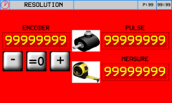
Procedure
-
Press
 and check the ENCODER box increases(Analog out +1 Volt)
 -
Press
 and check the ENCODER box decreases (Analog out -1 Volt)
 -
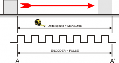
A - A' = The maximum space
-
Take note of the start position (A)
-
Zero-set the ENCODER:

-
Move the axis from A to A'
-
Take note of the reading in ENCODER box and write it in the PULSE box
-
Measure the distance from A to A' = space delta
-
Enter the A - A' space delta in the MEASURE box
Important:
-
PULSE must alway be greater than MEASURE (the best is “MEASURE x 10 = PULSE”)
-
Enter MEASURE in the selected unit measure. E.G. if a unit measure of 1/10mm is selected and the space delta is 133.5mm, enter 1335 in the MEASURE box
5.2 P.I.D.
| P.I.D. | |
The PI + FF calibration procedure:
Space feedback corrects the axis position according to the follow error reading.
Settings in yellow can be modified for the calibration.
Service data is in green and only used for the setup procedure.
| Parameter name | Unit measure | Default | Range | Description |
|---|---|---|---|---|
| VOLTAGE OUT | V | 0.0 | -10.0 – 10.0 | Output voltage, with 0.1V precision, sent directly to the device |
| OFFSET | V | 0.0000 | -99.9999 – 99.9999 | Voltage added to the analog output to compensate any supply voltage irregularities |
| SPEED | mm/min | - | - | The real axis speed |
| MAX SPEED | mm/' | 1000 | 0 – 9999999 | Axis speed at an analog output of 10V |
| POSITION | mm | - | - | The real axis position |
| DELTA | mm | 0.0 | - | Delta space between two positions |
| SET SPEED | mm/' | 0 | - | Axis speed during positioning |
| ACC. TIME | s | 1.00 | - | Acceleration time during positioning |
| DEC. TIME | s | 1.00 | - | Deceleration time during positioning |
| FEEDFORWARD | % | 100.0 | 0.0 – 200.0 | Percentage speed multiplier to generate the feed-forward quota of the analog output |
| PROP. GAIN | - | 0.010 | 0.000 – 9.999 | The follow error multiplier to generate the proportional quota of the analog output |
| T INTEGRAL | s | 0.000 | 0.000 – 9.999 | The integration time coefficient of the follow error. The error integration multiplier to generates the integral quota of the analog output |
| MAX FOLLOW ERR. | mm | 99999.9 | 0.0 – 99999.9 | The maximum drift between the calculated axis position and real axis position |
| FOLLOW ERR. | mm | - | - | The real follow error reading |
First complete the following procedures:
-
RESOLUTION: set the resolution.
-
MAX POSITION: enter a very large positive setting (e.g. 99999.9 mm)
-
MIN POSITION: enter a very large negative setting (e.g. - 99999.9 mm)
IMPORTANT! Essential conditions for the all procedures:
 Ensure that the emergency button shuts off the power to the motors so that the machine can be put in a safety condition.
All emergency conditions on the machine must be eliminated.
Procedures
| OFFSET | |
|---|---|
| 1 |  to start calibration to start calibration |
| 2 | Set OUT VOLTAGE = 0 |
| 3 | Regulate the OFFSET (directly by |
| 4 |  to quit calibration to quit calibration |
| Rotation direction and count | |
|---|---|
| An output voltage > 0 increases POSITION | |
| 1 | to start calibration |
| 2 | Enter VOUT = 1.0 |
| 3 | Check that POSITION increases |
| 4 | to exit calibration and check that VOUT goes to 0 immediately |
| 5 | If the motor does not rotate in the correct direction, change the drive setup or cabling |
| Maximum speed | |
|---|---|
| Setting the maximum axis speed (10V output) | |
| 1 | to enter calibration |
| 2 | Enter VOUT > 1.0 (as close to 10V as possible) |
| 3 | Note the SPEED reading |
| 4 | Calculate the MAX SPEED: MAX SPEED = (10 x SPEED) / VOUT |
| 5 | to exit calibration and check that VOUT goes to 0 immediately |
| 6 | Enter the above calculation result in MAX SPEED |
| Space Feedback | ||||||||||||||
|---|---|---|---|---|---|---|---|---|---|---|---|---|---|---|
| Important: first complete all previous procedures | ||||||||||||||
| 1 | Enter FEEDFORWARD = 100.0 | |||||||||||||
| 2 | Enter PROP. GAIN = minimum setting (0.001) | |||||||||||||
| 3 | If FOLLOW ERR is not 0, now this reading will reduce with an axis movement | |||||||||||||
| 4 | Enter DELTA = any distance and SET SPEED = a speed (nearly MAX SPEED) | |||||||||||||
| 5 |  to start the axis movements to start the axis movements |
|||||||||||||
| 6 | The axis moves forward by the distance in DELTA at the speed in SET SPEED | |||||||||||||
| 7 | The axis then returns to the start position and repeats the movement | |||||||||||||
| 8 | During the movements note the FOLLOW ERR reading and vary FEEDFORWARD and PROP. GAIN to keep it as low as possible. Setting rules
|
|||||||||||||
| 9 | When the axis movement overshoots MAX FOLLOW ERROR you will see the warning symbol |
|||||||||||||
| 10 |  to quit the procedure to quit the procedure |
|||||||||||||
5.3 Linearization
| LINEARIZATION | |
if the mechanics is not linear in this page you can fill a conversion chart between positions read from the transducer (real angle) and posizon correct (linearized).
5.3.0.1 Table Center Correction
 | 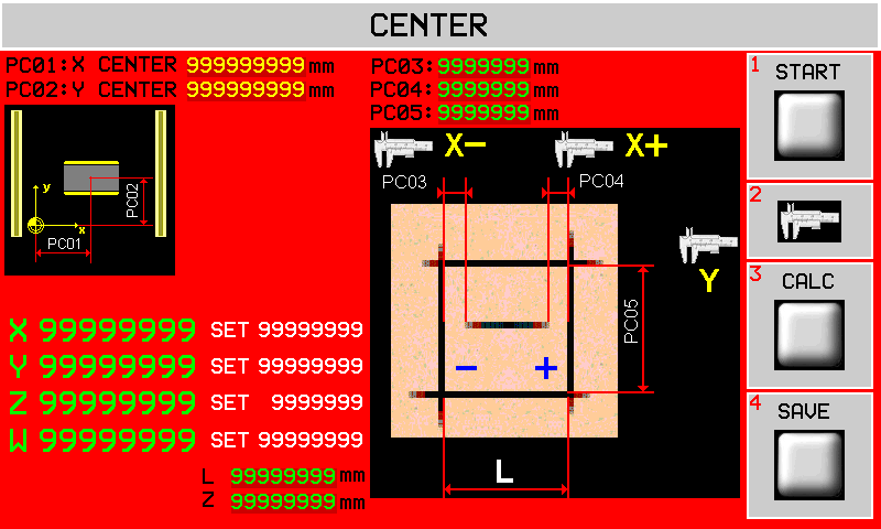 |
||||
 | START | | CALC | | SAVE |
Center Correction Procedure
-
Select Manual mode.
-
Zero-set the Z axis on the slab top.
-
Power the disk and wait until it reaches set speed.
-
START to make the 5 cuts as shown. The cuts are made at 5 mm depth.
-
Measure the 3 distances (X-, X+, Y) and enter them in PC03, PC04, PC05.
-
CALC to make the corrections. PC01 and PC02 will change reading. CALC can only be used once, to repeat exit the screen and enter again.
-
SAVE to save the corrections.
-
Exit and enter this screen again to repeat points 1, 2 and 3.
-
Check that PC03 = PC04 and PC05 = L mm.
| Parameter | Unit Measure | Default | Range | Description |
|---|---|---|---|---|
| PC01 : X CENTER | mm | 1699.10 | 0 - 999999.99 | Copy of X table center |
| PC02 : Y CENTER | mm | 1765.60 | 0 - 999999.99 | Copy of Y table center |
| PC03 : | mm | 0.00 | -999.99 ~ 999.99 | Measure as shown for the X center correction |
| PC04 : | mm | 0.00 | -999.99 ~ 999.99 | |
| PC05 : | mm | 0.00 | 0 ~ 9999.99 | Measure as shown for the Y center correction |
| L: | mm | 200.00 | 0 ~ 999999.99 | L = side of the cut |
| Z: | mm | 5.00 | 0 ~ 999999.99 | Depth of the cuts |
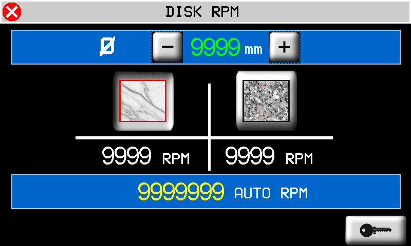
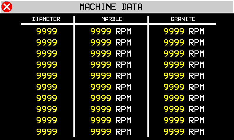
6. Disk RPM Chart
MAIN MENU  | 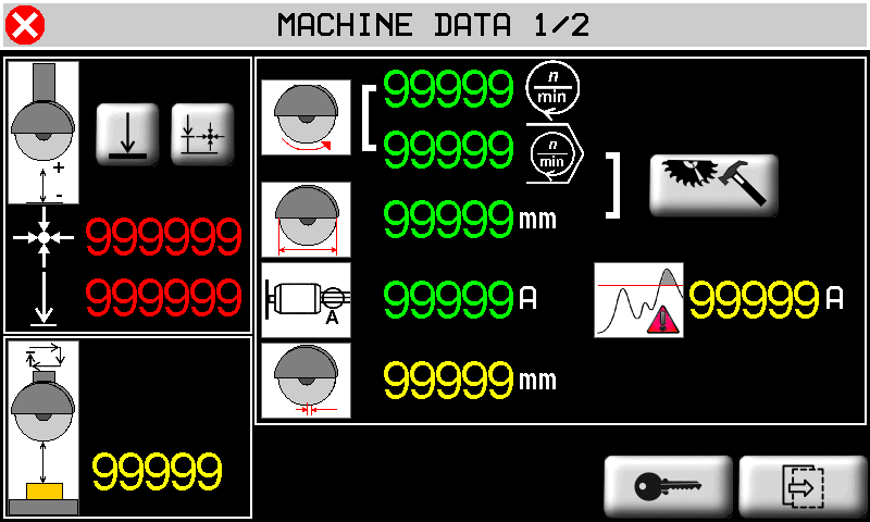 |
|
 |  |
|
 password 462 |
||
 |
||