Indice
P1K31FR30-001 - 3 axis bridge saw: User Manual
PS Bernard sistemare la tabella a “10.2.3.1.2. POCKETING - Parametri lavorazione “Tasca””
Mi manca da
- rimuovere le immagini dei zeri profili
- aggiornare elenco allarmi (ma spetto versione definitiva)
- aggiornare elenco warnings
| Document | P1K31FR30-001 | ||
|---|---|---|---|
| Description | User manual | ||
| Drawn up | Riccardo Furlato | ||
| Approved | Draft | ||
| Link: | http://www.qem.eu/doku/doku.php/en/strumenti/qmoveplus/j1k31/mdu_p1k31fr30-001/funzionamento | ||
| Languages | English | ||
| Release | Description | Notes | Date |
| 01 | New Manual | 26/05/14 | |
All rights reserved on this manual. No part of this document can be copied or reproduced in any form without prior written authorisation. QEM does not insure or guarantee its contents and explicitly declines all liability related to the guarantee of its suitability for any purpose. The information in this document can be changed without notice. QEM shall not be held liable for any error or omission in this document. QEM® is a registered trademark.Microsoft® and MS-DOS® are registered trademarks and Windows® is a trademark of Microsoft Corporation.
Table of Contents
1. General Characteristics
Description
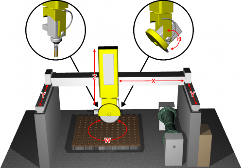
The P1K31FR30 - 001 software can be installed on the Qmove+ J1-K31-FR30, J1-P31, J1-P51, J1P71 hardware and is designed to control a bridge saw with 3 to 5 axes, for marble and granite. The salient features of the P1K31FR30 - 001 are described below.
Axes
-
Axes X, Y, Z controlled by PID on space (brushless motors with servo drives and brushless motors).
-
Axis W for the table rotation is manually controlled, with the operator entering the position on the controller
-
Axis H for the disk inclination is manually controlled, with the operator entering the angle on the controller
Optional
-
Axis W for the table rotation, with positioning accounting for inertia (asynchronous motor and V/F inverter) without interpolation.
-
Axis H for the disk inclination, with positioning accounting for inertia (asynchronous motor and V/F inverter) without interpolation.
Work Processes
-
Semiautomatic functions for positioning the axes and for single cuts.
-
Multiple cuts for block and slab cutting, with table rotation (W) for tile cutting.
-
Straight profiling with horizontal or vertical disk.
-
Step cutting with inclined disk (on machines that have disk inclination).
-
Straight profile finishing, using the face of the disk (interpolation of YZ).
Drawing
-
Profile programming by a miniCAD, embedded on the controller.
-
Import of profiles, saved on DXF file, by the “Profile Importer” conversion software (optional).
Work modes
-
Repeat the programmed shape.
-
Set the precision of the finishing.
-
Modify the speed of disk motion during the work cycle.
-
Compensation of the disk thickness and the disk diameter
Accessory functions, messages and alarms
-
Select the language
-
View the profile and the disk position, during the work cycle.
-
Diagnostics of the inputs and the outputs.
-
Backup and restore of the data on non volativle memory (FLASH EPROM).
-
Messagges for active faults, to assist troubleshooting.
-
Help Messagges.
-
Modbus interface for reading the absorbed current of the disk.
Optional Features (some not documented in this manual)
-
Profiles made with rotating table (similar to a vertical lathe).
-
Profiling with horizontal disk or vertical disk (XZ or XY interpolation).
-
Copying by photocell from a cardboard shape or black drawing on a whiteboard.
-
ISO manager with G code interpreter
Modbus Interface
-
The USER serial port can create a MODBUS RTU (RS485) network, for reading the disk rpm.
-
Serial port connection for a magnetic rule, for reading the absolute position of the axis.
1.1 Typical work results
 Multiple cuts |  Tile cuts |  Arc tiles |
 Profile roughing |  Profile finishing | 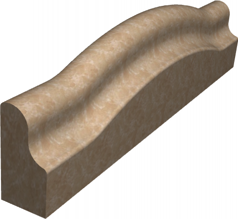 Curved profile roughing |
 Column roughing | 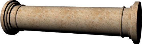 Column finishing | 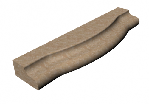 Horizontal profile roughing |
 Circular Top roughing | 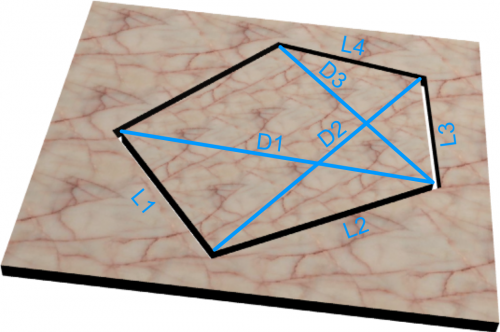 Spiral stairs |  G-code relief |
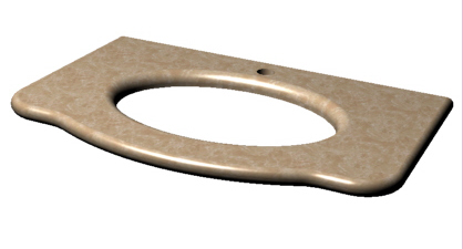 Top milling | 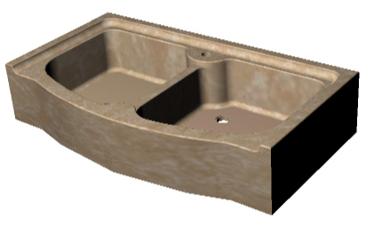 Sinks & drains | 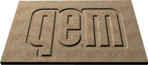 G-code texting |
2. Hardware J1-K31-FR30

2.1 Function Keys and LEDs
| Key | Icon | Function | Led | . | Key | Icon | Function | Led |
|---|---|---|---|---|---|---|---|---|
| F1…F3 | Not Used | . | F11 | | Semiautomatic = ON | Semiautomatic status | ||
| F4 | | Enclosures | Enclosure open status | . | F12 | | Table UP | Table up |
| F5 | - | Not used | . | F13 | | Table DOWN | Table Down | |
| F6 | | Y Laser ON/OFF | Laser status | . | F14 | | Table Rotation Anticlockwise | - |
| F7 | | X Laser ON/OFF | Laser status | . | F15 | | Table Rotation Clockwise | - |
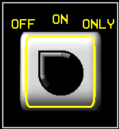
| F8 | | Water ON/OFF | Water status | . | F16 | | Disk ON/OFF | Blink is starting, On is started |
| F9 | | Alarm = ON | - | . | F17 | | Mill ON/OFF | Blink is starting, On is started |
| F10 | | Quit or prolonged MAIN | - | |||||
2.2 Symbols and keys
| Button | Description | ———————– | Top Bar Symbol | Description |
|---|---|---|---|---|
| | Press to confirm | | Manual | |
| | Select | | Emergency | |
 | Previous screen | | Automatic | |
 | Next screen | | Function mode | |
 | Reserved Area | | Not initialized | |
| | Open file on SD card | | Setup Locked/Unlocked | |
| | Save | |||
 | Work preview | |||
 | Yellow settings can be changed | |||
3. STARTUP
| START | | OR  to bypass |
 |
||
| HOMING |  | OR to bypass |
 | ALWAYS run Homing before going to MANUAL. Homing not OK limits machine operation. |
|
|---|---|---|
| |
||
| MAIN MENU |  | |
4. Main Menu
  | |
|
  |   |
|
  |   |
|
 |   |
|
  |   |
|
5. Homing
| | |
||
| | Run Homing | | Homing OK |
| | No Homing | | Homing not OK |
 | Delta Error | ||
| | ALWAYS run Homing before going to MANUAL. Homing not OK limits machine operation. |
||
|---|---|---|---|
5.1 Homing Procedure
-
Select one or more Axis

-
external Machine Start button
-
Homing successful =

-
Homing not successful =

-
The Delta Error is next to each Axis
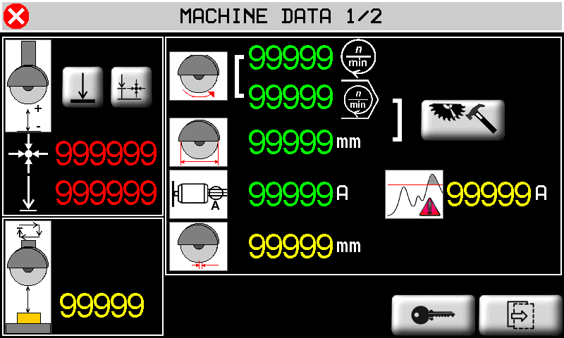
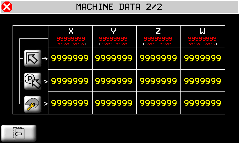
6. Machine Data
| MAIN MENU | |
|
 |  |
|
 |  |
|
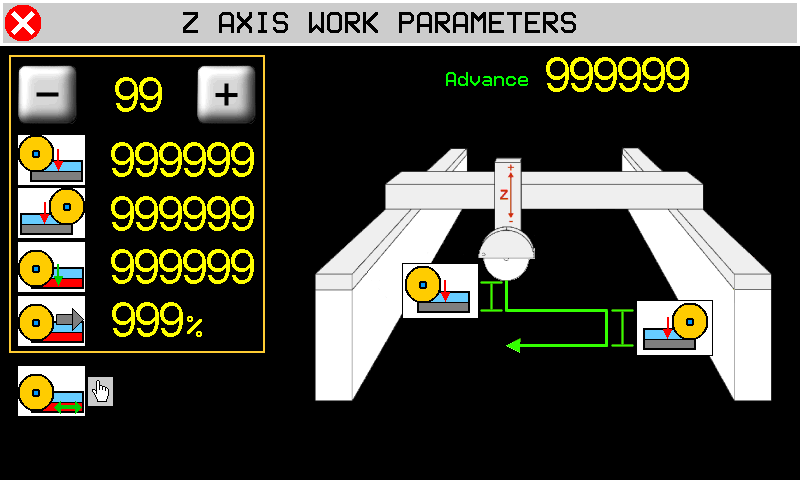
Set Default Z min position  | Auto-set Z min position  | Set SAFE HEIGHT 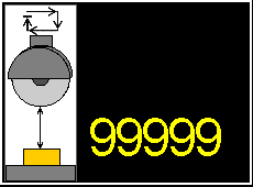 |
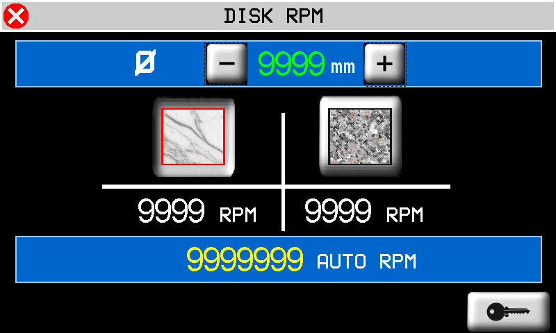
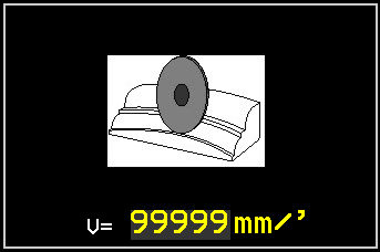
 Disk RPM Disk RPM | | Set diameter and RPM |
 Disk absorbed current Disk absorbed current |  Set Maximum current Set Maximum current |  Set Disk thickness Set Disk thickness |
 Start position Start position |  Park position Park position |  Change tool position Change tool position |
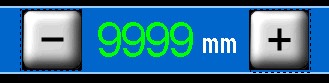
| DISK DIAMETER & RPM | ||
|---|---|---|
 Disk diameter Disk diameter |  Marble Marble |  Granite Granite |
 AUTO RPM based on diameter - Set RPM override of auto AUTO RPM based on diameter - Set RPM override of auto |
||
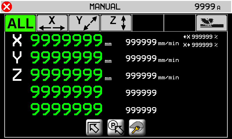
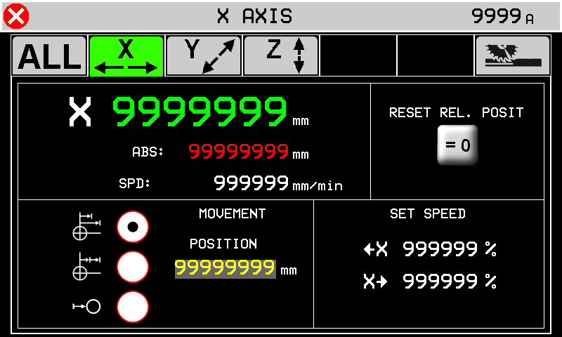
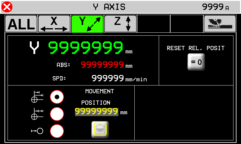
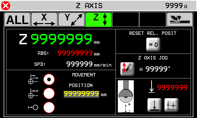
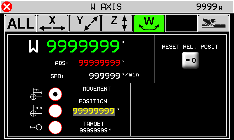
7. Manual/Semiautomatic
| | | ||
| | |
||
  |   |
||
  |   |
||
  |
|||
 |  |
| | Go to START | | Go to PARK | | Go to TOOL CHANGE |
 |  |
|
| SET TARGET POSITION 9999 mm | - - -  | Auto-set ZERO position  |
 |  | Disk Correction  OFF OFF  ON ON |
 |  | Z jog   |
| Default Z min Auto-set Z min |
||
 |  | |
 | 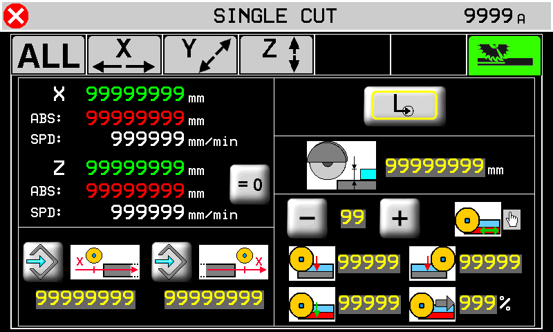 | |
 | Auto-set position | 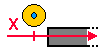 | X Start Cut position | 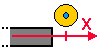 | X end Cut position |
 | Single cut |  | Step cuts with multiple depth increases | 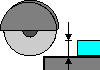 | Cut depth |
| Number of Steps (max 10) |  | Step depth for (X+) |  | Step depth for (X-) | |
Last cut direction    |  | Last cut depth |  | % Speed change of Last Cut | |
8. Multiple Cuts
| | |
||
| | |
||
| |  |
||
| |  |
||
| |  |
||
8.0.1 No Rotating Table
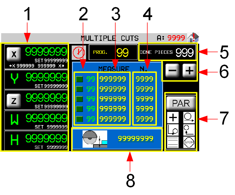 | 1 Target count and position 2 Work step now 3 Cut width (Y) 4 Number of cuts to make 5 Piece counter 6 Scroll work program list 7 Work Parameters 8 Cutting depth (Z) |
|
8.0.2 Rotating Table

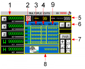 | 1 Target count and position 2 Work step now 3 Cut width (Y) 4 Number of cuts to make 5 Cutting depth (Z) 6 Piece counter 7 Scroll work program list 8 Work Parameters 9 Table Rotation (W) |
|
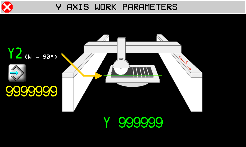
8.0.3 Axis parameters
| | NO ROTATING TABLE 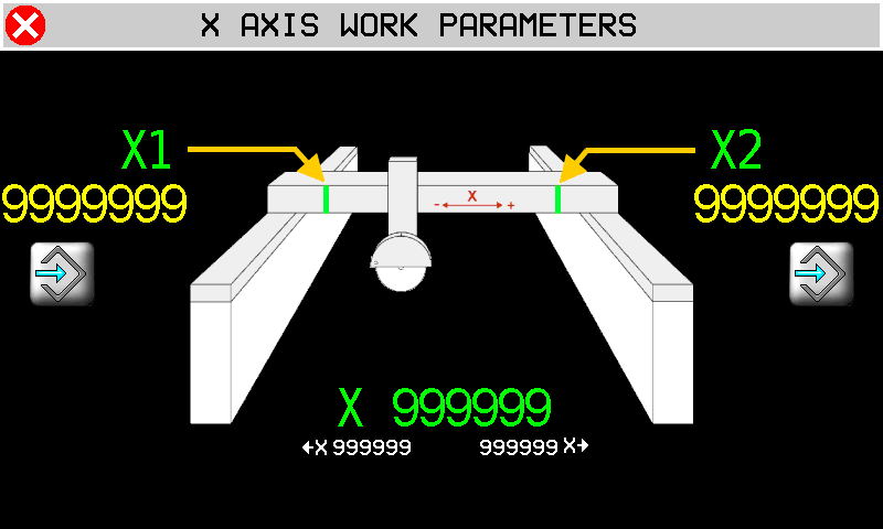 | WITH ROTATING TABLE 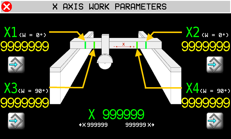 |
||||
| | Auto-set position X1 + X2 = table (W) at 0°…..X3 + X4 = table (W) at 90° N.B. the disk exits the slab by its radius before reaching X1 - X2 or X3 - X4. | |||||
| |  |
|||||
| | Auto-set Y2 = start position with table (W) at angle | |||||
| X Start position | | X End position | |||
| |  |
|||||
| Advance 99999 | Number of Steps | Last cut direction | ||||
| Step depth for (X+) cut | | Step depth for (X-) cut | |||
| Last cut depth | | Last cut % Speed change | |||
8.0.4 Work Parameters
 |  |
|
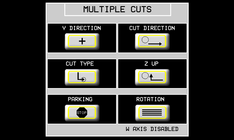
| Y DIRECTION | POSITIVE direction to end of cut  | NEGATIVE direction to end of cut  |
| CUT DIRECTION | X+ only  | TWO-WAY Cut  |
| CUT TYPE | SINGLE cut | STEP cut |
| Z UP | Z UP when X is at min position | X and Z exit slab TOGETHER  |
| END POSITION | Disk STOPS at end of work  | Disk goes to PARK at end of work  |
| ROTATION | NO ROTATING TABLE  | WITH ROTATING TABLE  |
9. Tilted Cuts
| |  |
||
| | |
||
| | |
||
| | |
||
| |  |
||
| | 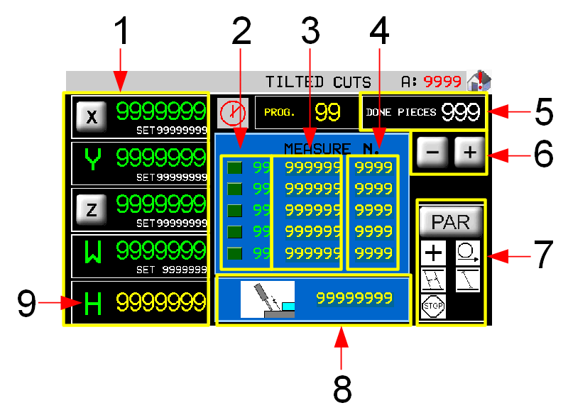 | 1 Axis parameters Target count and position 2 Work step now 3 Cut width (Y) 4 Number of cuts to work 5 Piece counter 6 Scroll work program list 7 Work Parameters 8 Cutting depth (Z) 9 Set disk angle (H) |
| | Axis parameters - see Multiple Cuts | |
9.0.1 Work Parameters
| |  |
|
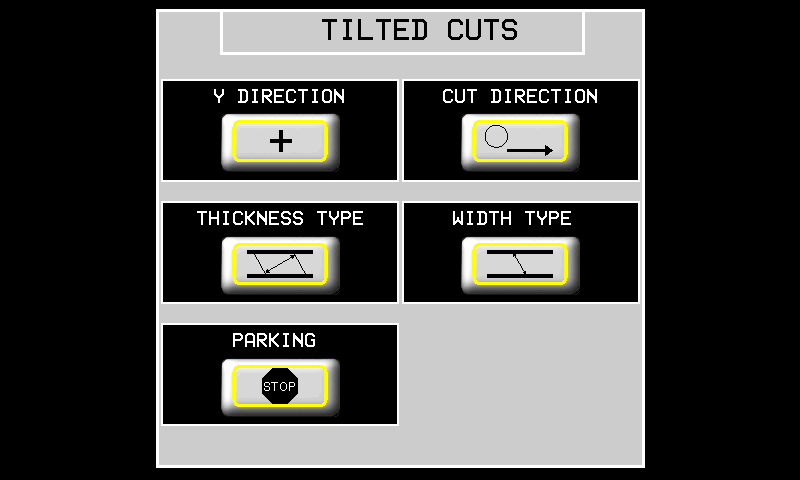
| Y DIRECTION | POSITIVE direction to end of cut | NEGATIVE direction to end of cut |
| CUT DIRECTION | X+ Cut only | TWO-WAY Cut |
| THICKNESS TYPE | Thickness at 90° to the cut  | Thickness PARALLEL to the slab surface  |
| DEPTH TYPE | Depth = along the disk  | Depth = 90° to the slab surface  |
| END POSITION | Disk stops at end of work | Disk goes to PARK at end of work |
10. Programs
| | |
||
| | |
||
 |  |
||
 |  |
||
 |  |
||
| RUN  |  |
||
10.0.1 Program List Filters
 Using the program's list filters is possible to get quickly the desired program, rather than scroll entire available list. The system permit two type of filtering which can be combined each other:
-
Filter on program description
-
Filter on program type
Warn that “Type” mean:
| Type | Description |
|---|---|
| 0 | Show any program |
| 1 | Show only tagli sagomati/profilatura programs |
| 2 | Show only fresatura programs |
| 3 | Show only taglio poligoni programs |
10.1 PROFILES
| | |     |
||
| | |
|||
| | |
|||
| |    |
|||
  |   |
|||
  |
||||
 |  |
|||
10.1.1 PROFILE - CAD
 | 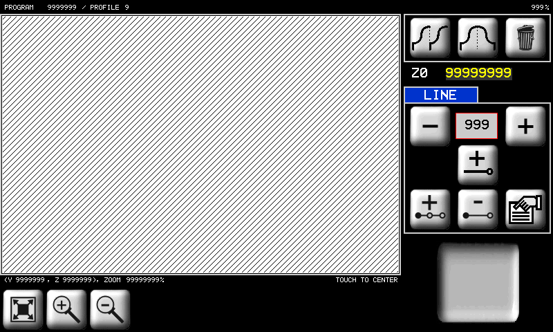 |
|||||||
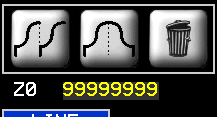 | | Copy | | Mirror copy | | Delete the object | Z0 = origin Y coordinate = 0 |
|
| | Zoom in | | Zoom-out | | Fit to screen | |||
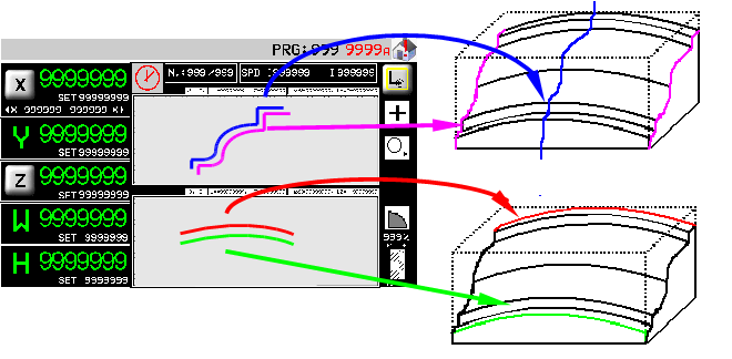
 | | YZ plane = Profile shape | 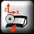 | XZ plane = Curved profile | ||||
 | | Scroll and select a line | ||||||
| | Add a line | | Insert a line | | Delete a line | | Line properties | |
 |  |
|||||||
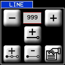
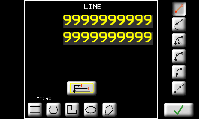
| Line Options |       |
|||||||
 | Absolute position from origin |  | Incremental position from start of line |
|||||
| - - - - - - - - - - - | - - - - - - - | - - - - - - - - - - | - - - - - - - | - - - - - - - - - - | - - - - - - - | - - - - - - - - - - | - - - - - - - | - - - - - - - - - - |
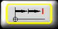
LINE  | | Enter the end point |
TANGENT LINE  | 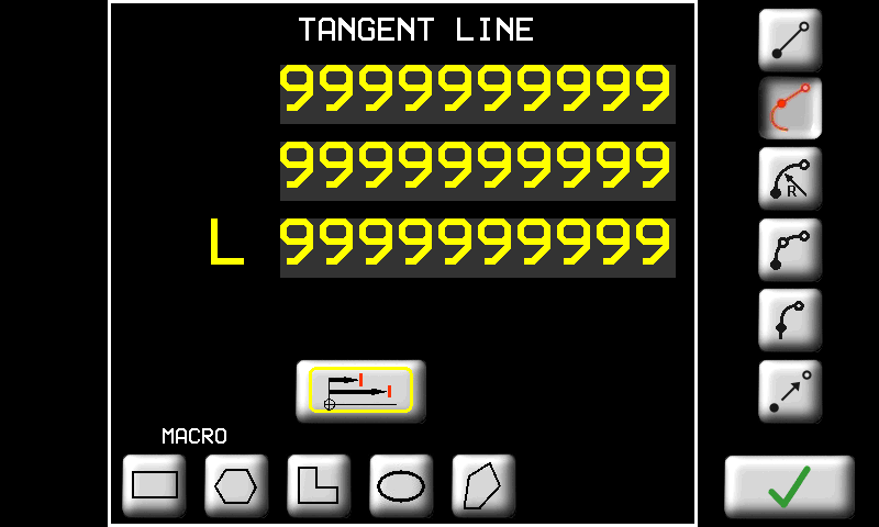 | OR enter Y (or X) 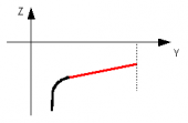 |
OR enter Z (or Y) 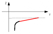 |
||
OR enter L = length 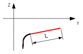 |
||
RADIUS ARC  | 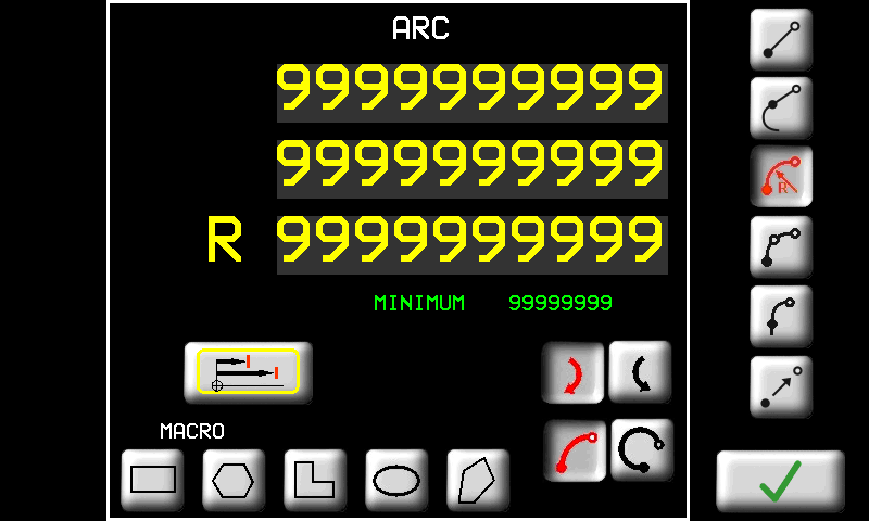 | Enter End point and Radius MINIMUM the minimum radius possible |
 clockwise clockwise 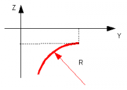 |
||
 anticlockwise anticlockwise 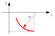 |
||
Also enter the curve direction clockwise OR clockwise OR  anticlockwise anticlockwise small arc OR small arc OR  wide arc wide arcThe screen shows the minimum radius possible |
||
3 POINT ARC  | 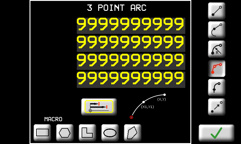 | Enter End point and Middle point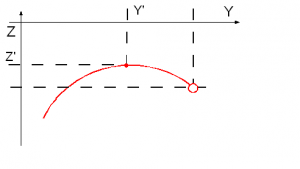 |
TANGENT ARC  | 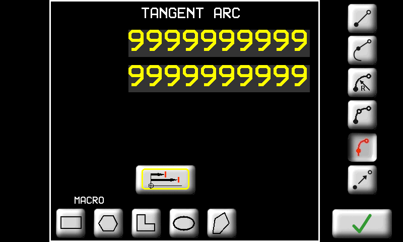 | Enter End point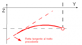 |
TRANSFER  | 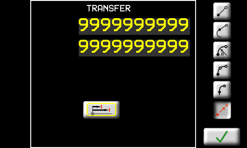 | Movement with no cut. Enter target point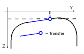 |
 | The software automatically corrects an undercut profile line see other manual |
|
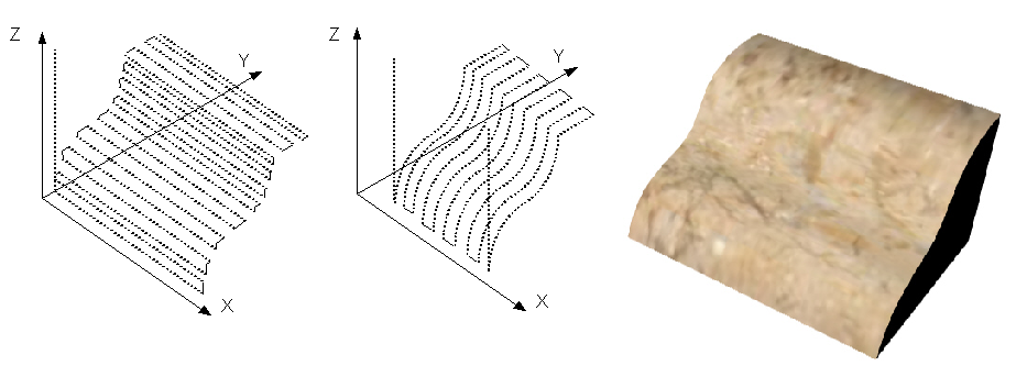
Profiles with straight cuts
Draw a profile on the Y-Z plane
-
vertical disk

-
horizontal disk

Never draw profiles on the other planes.
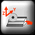
Profiles with curved cuts
1. Draw a profile on the usual Y-Z plane
-
vertical disk
-
horizontal disk
2. Draw the curved cut
-
on X-Z plane for vertical disk

-
on X-Y plane for horizontal disk

To change plane touch the immagine stessa.
10.1.2 PROFILES - CAM


 | 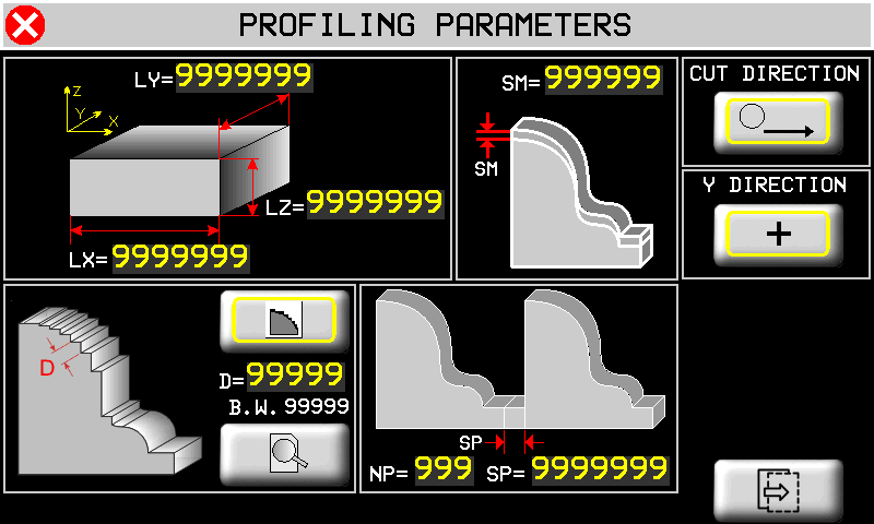 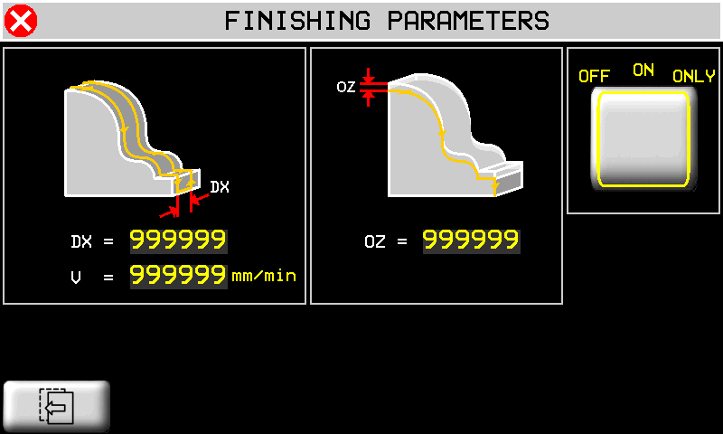  |
| | Profile Finishing is NOT possible on curved profiles. |
|---|
Slab size. Optionally you can enter slab size. It will draw in gray color both in cad page and in preview page 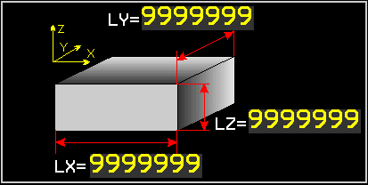 | Extra Material on the profile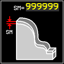 | Cut X+ only Two-way Cut | Y direction   |
|
Cut Spacing type 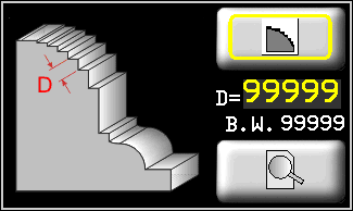 | Cut spacing  | Disk diameter  | Cut Preview | |
 Spacing along profile 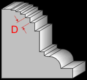 |  Spacing along Y Critical points ON 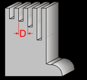 |  Spacing along Y Critical Points OFF |
||
Repeat - Vertical Disk 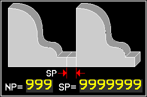 | Repeat - Horizontal Disk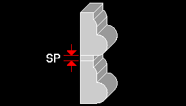 | NP = Number of Repeats SP = Space between repeats |
||
 | Work sequence OFF Profile only 0N = Profile and Finishing ONLY = Finishing only | DX = Disk path spacing V = Finishing speed OZ = Finishing depth |
||
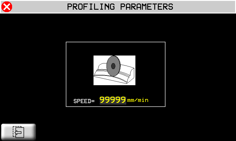
 | Curved profiles. Set the maximum cut speed. |
|||
10.2 TOPS
| | | |||
| | | |||
| | | MILLING  OR DISK CUT  |
||
| | |
|||
 |  |
|||
| | |
|||
10.2.1 TOPS - CAD
| | 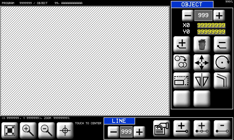 |
|||
| | Drawings are always made with positive X and Y. | |||
Fit to screen  | Zoom in  | Zoom out  | Touch to center a point on 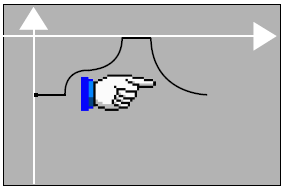 |  |
 | Scroll and Select objects. The selected object is black. Other objects are yellow. |  | Origin of the object. | |
 | Object tools | |
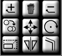
 Add new object Add new object |  Delete all objects Delete all objects |  Delete object Delete object |
 Copy an object Copy an object |  Move an object Move an object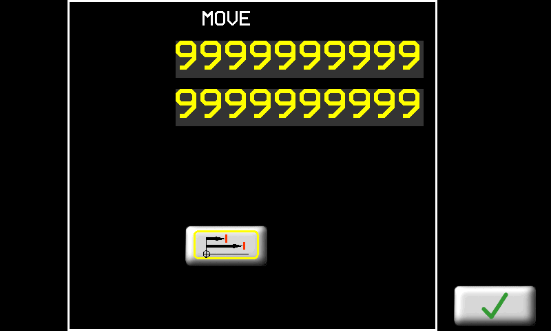 |  Rotate an object Rotate an object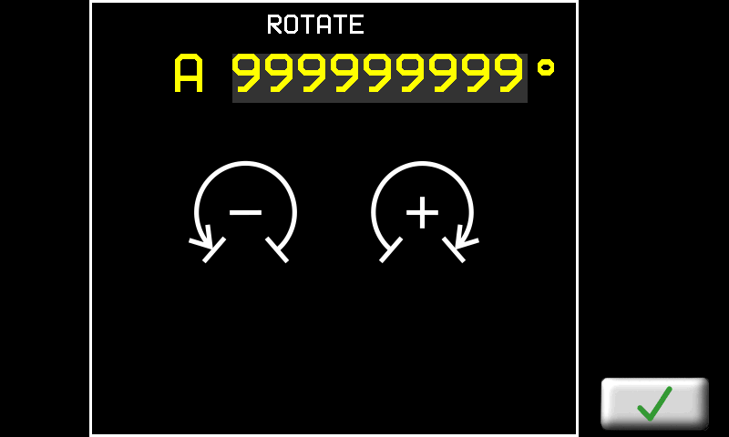 |
 Resize an object Resize an object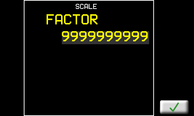 |  Mirror copy an object Mirror copy an object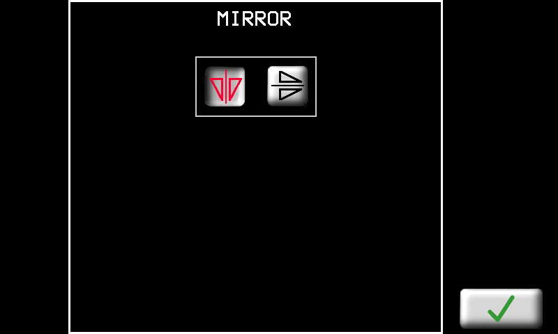 |  Draw a Parallel edge Draw a Parallel edge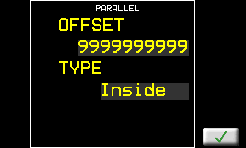 |
10.2.1.1 CAD Tools
 | CAD Line tools | ||
 000 000  | Scroll and select a line |  | Line properties |
| Add line |  Insert line Insert line |  Delete line Delete line |
|
| MACROS | Automatic CAD functions | |
|---|---|---|
Rettangle.  | 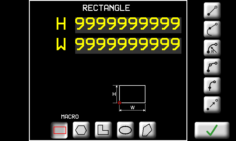 | H = height W = width. 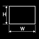 |
| Regular Polygon  | 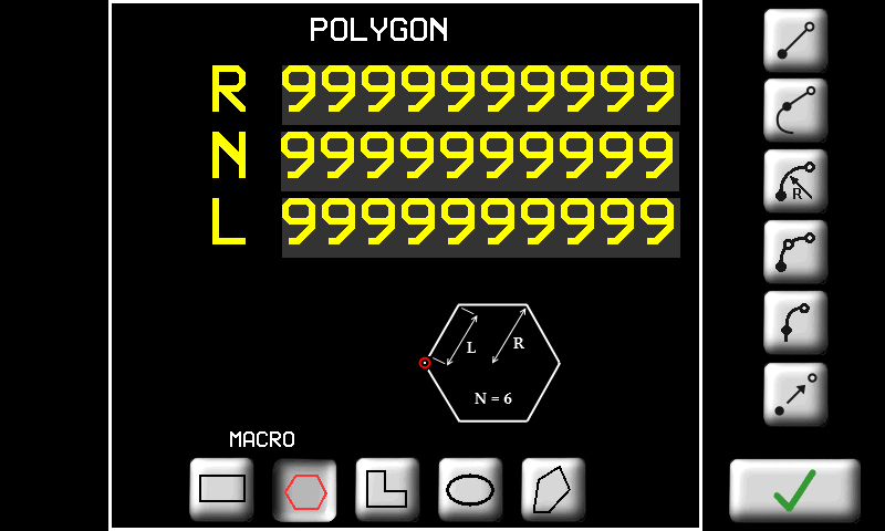 | N = number of sides R radius OR L length of side 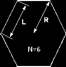 |
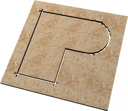
L Shape  | 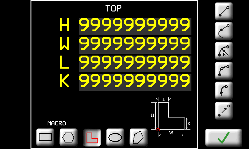 | H W L K as shown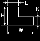 |
Ellipse.  | 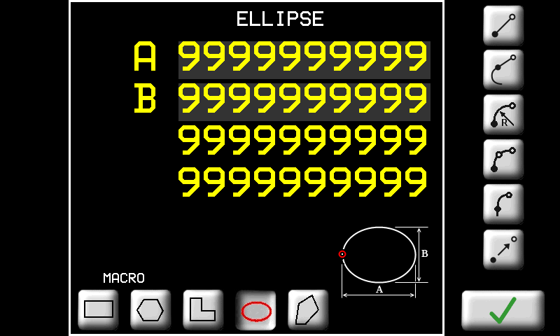 | A = diameter 1 B = diameter 2 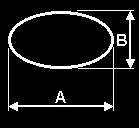 |
| Irregular Polygon  | 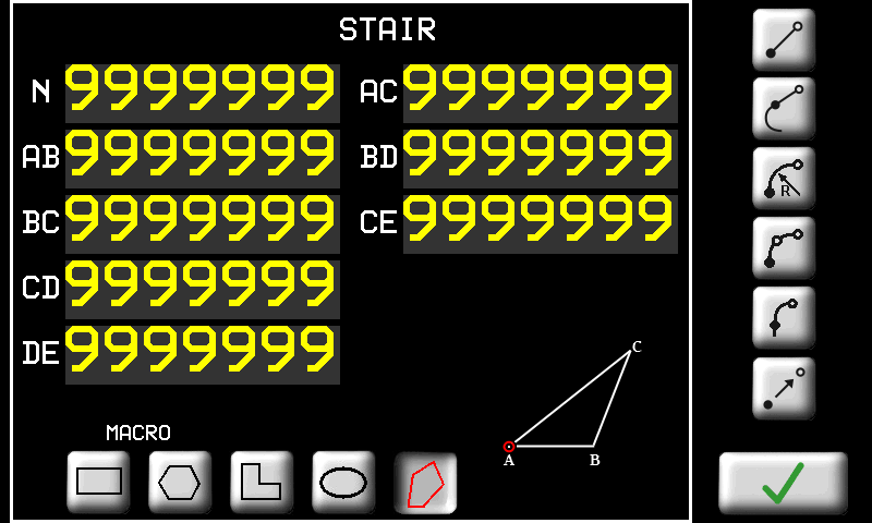 | As shown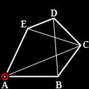 |
| LINES | Line drawing tools | |
|---|---|---|
| | Absolute positions = from origin | |
| | Incremental positions = from end of last line | |
| LINE | | Enter the end point |
| TANGENT LINE | | Y (or X) axis Z axis OR Length |
| RADIUS ARC | | Radius Arc Enter the end point and radius |
| Also enter the curve direction clockwise OR anticlockwise small arc OR wide arc The screen shows the minimum radius possible |
||
| 3 POINT ARC | | Arc through 3 points Enter the middle point and end point |
| TANGENT ARC | | Arc at a tangent to the previous line Enter the end point (the others are automatic) |
| TRANSFER | | Transfer with no cut Enter the point to start work again. The transfer line is not cut |
10.2.2 DISK CUT - CAM
 |  | |
Mettere il numero di tipo PROFILE-TOP-DISKCUT in ogni sezione
 | Tool on left or outside |  | Tool on right or inside |  | Extra material on edge |
 | Slab thickness |  | Extra Corner Cut |  | Shorter Corner Cut |
 | Extra depth into table |  | H = Slab length L = Slab width |  | Tangent retta Disk Segment of Arc Cut |
| - - - - - - - | - - - - - - - - - - - - - - - - - - - - - - - | - - - - - - - | - - - - - - - - - - - - - - - - - - - - - - - | - - - - - - - | - - - - - - - - - - - - - - - - - - - - - - - |
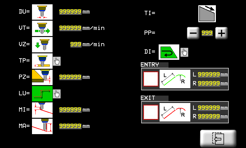
10.2.3 MILL CUT - CAM
| |   |
|
| |  |
|
| - - - - - - - - - | - - - - - - - - - - - - - | - - - - - - - - - | - - - - - - - - - - - - - | - - - - - - - - - | - - - - - - - - - - - - - |
 | Set Tool Diameter |  | Set Cutting Speed |  | Set Z- Down Speed |
 | Cut on left |  | Cut on right | ||
 | SINGLE cut to full depth |  | STEP cuts with increasing depth |  | Step depth |
| Sloping cut function - Direction of slope | |||||
|---|---|---|---|---|---|
 | Depth increase = X increase |  | Depth increase = X decrease | ||
 | Depth increase = Y decrease |  | Depth increase = Y increase | ||
 | Start depth |  | Final depth |  | Cut order, normal (from start point to endpoint) or reverse (from end point to start point). |
 | PP = Start point Set the start point of the work |
Closed object 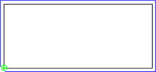 | Open ended object 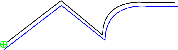 |
 Object Object Percorso utensile Percorso utensile | Open ended objects must start at an end |
CLOCKWISE 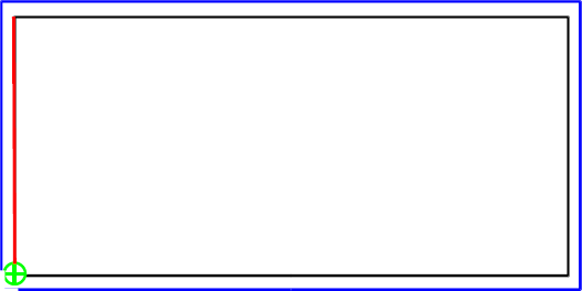 | ANTICLOCKWISE 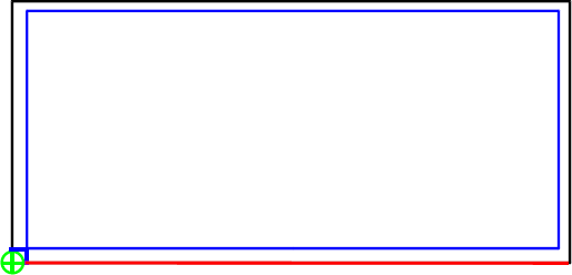 |
 Direction of First Cut Direction of First Cut | Not valid for open ended objects |
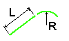 | ENTRY/EXIT Set an approach path for the tool. L = straight section R = radius of a curved section. |
 |  |
 ENTRY PATH ENTRY PATH | EXIT PATH |
| Closed objects and inside cuts do not ENTER/EXIT on corners | 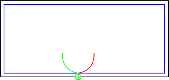 |
10.2.3.1 TOPS - CAM Program
| |  | Symbols on Objects |
The selected line is red 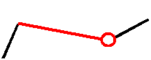 |
||
3 POINT ARC 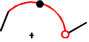 |
||
 |
| Scroll and Select from CAM list | |||||||
|---|---|---|---|---|---|---|---|
 | | Add a CAM | | Delete a CAM | | CAM properties | |
| | Fit to screen | | | ||||
| Set the CAM | |||||||
 | | Work OK CAM In Program | | Work OFF CAM Not in Program | | CAD object modified | |
 | Select object | |
 | 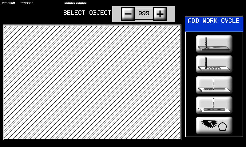 |  Mill Cut Mill Cut |
 Core Drill Recess Core Drill Recess |
||
 Mill Recess Mill Recess |
||
 3D Recess 3D Recess |
||
 Disk Cut Disk Cut |
||
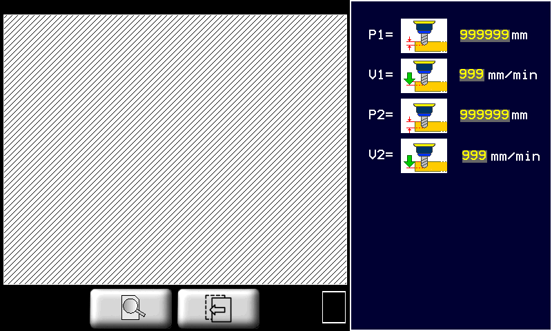
10.2.3.1.1 CORE DRILL RECESSING
| |   |
|
| |  |
|
L'area interna di una geometria chiusa viene svuotata tramite foratura. Tale lavorazione calcola la posizione dei fori secondo una modalità impostata con i seguenti parametri.
| | Set Tool Diameter |  | AUTOMATIC drilling |  | Press START to drill each hole |
 | Edge hole spacing |  | Extra space between holes and inside edge | ||
 | X hole spacing |  | Y hole spacing | ||
| Hole Path Layout | |||||
 | EDGE holes along inside edge |  | HOR horizontal path |  | VER vertical path |
 | EDGE+HOR inside edge + horizontal |  | EDGE + VER inside edge + vertical | ||
P1 | First depth of drilling | V1 | First drilling speed | ||
P2 | Final drilling depth | V2 | Final drilling speed | ||
| P1 must be less than P2 | V1 is normally less than V2 | ||||
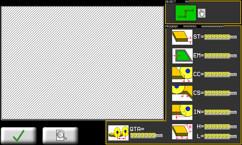
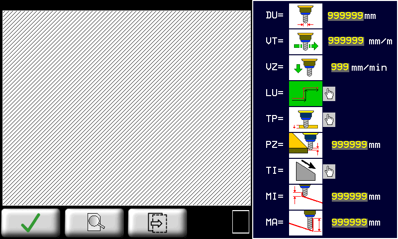
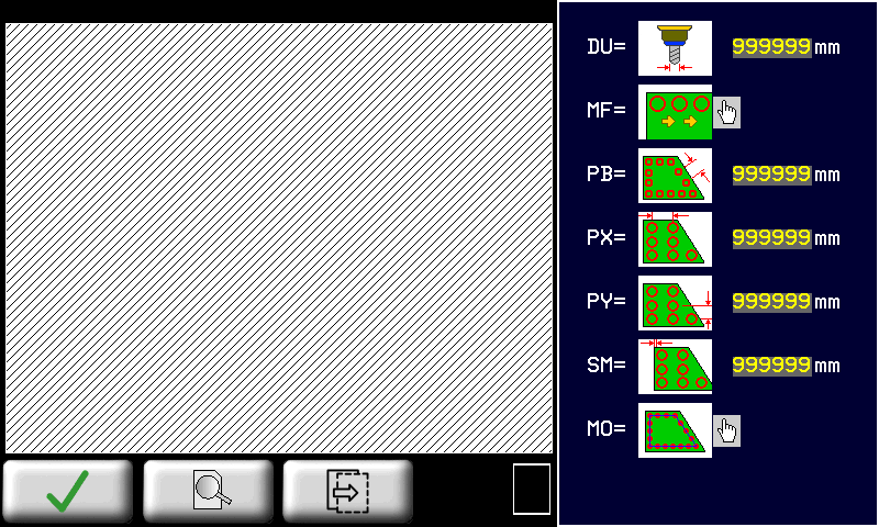
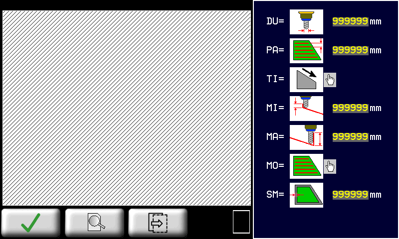
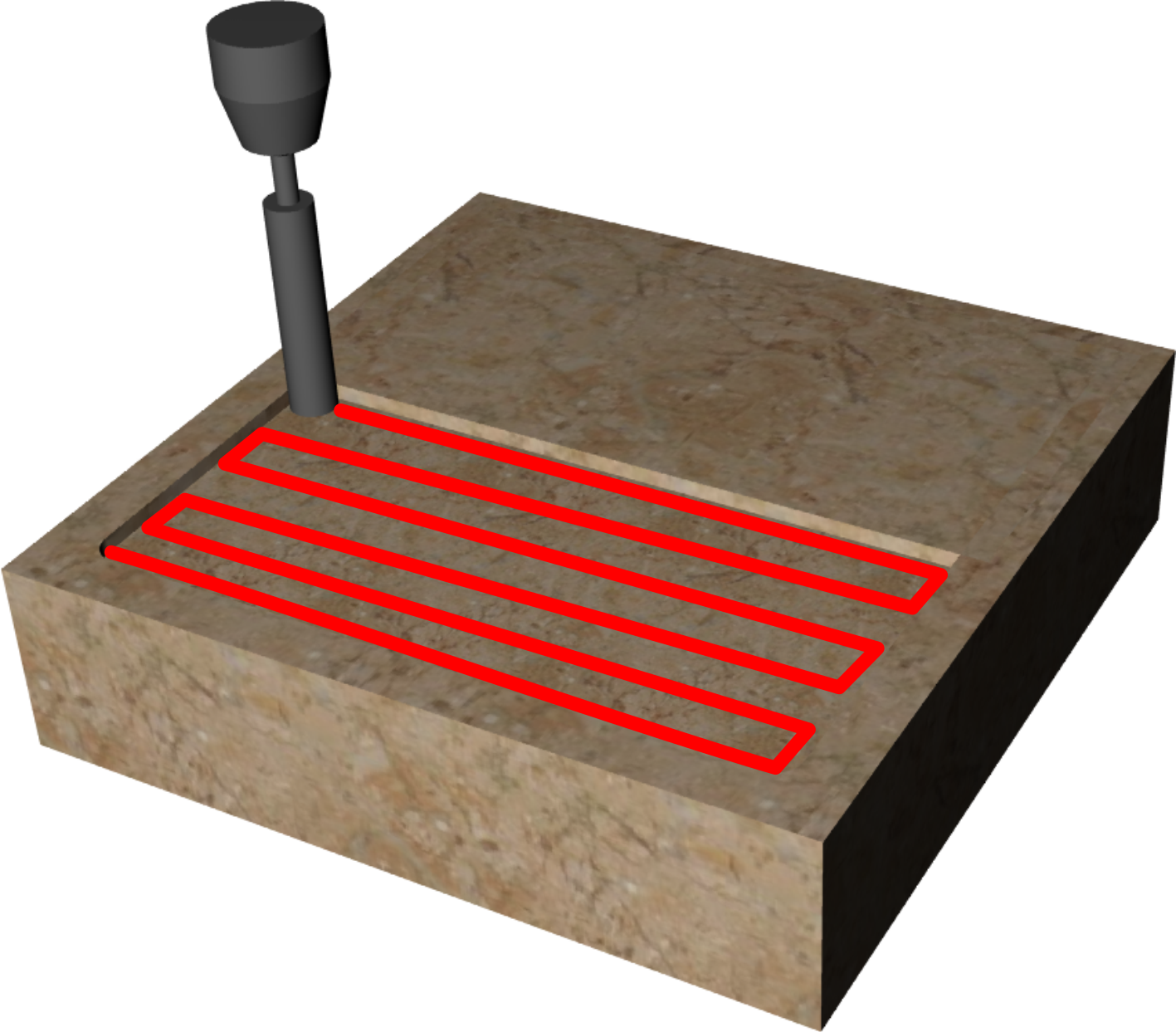
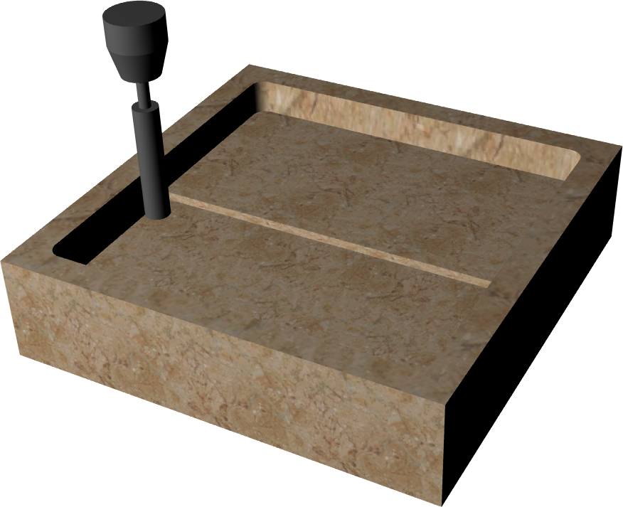
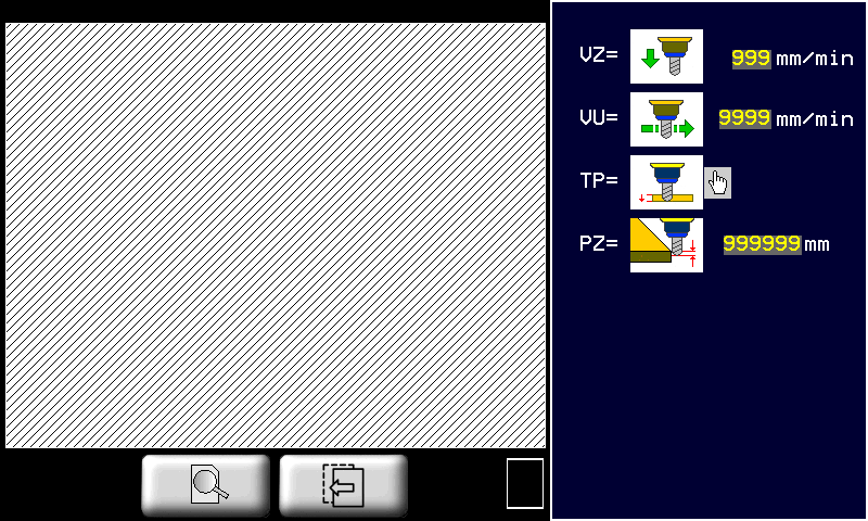
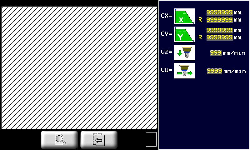
10.2.3.1.2 MILL RECESSING
| |  |   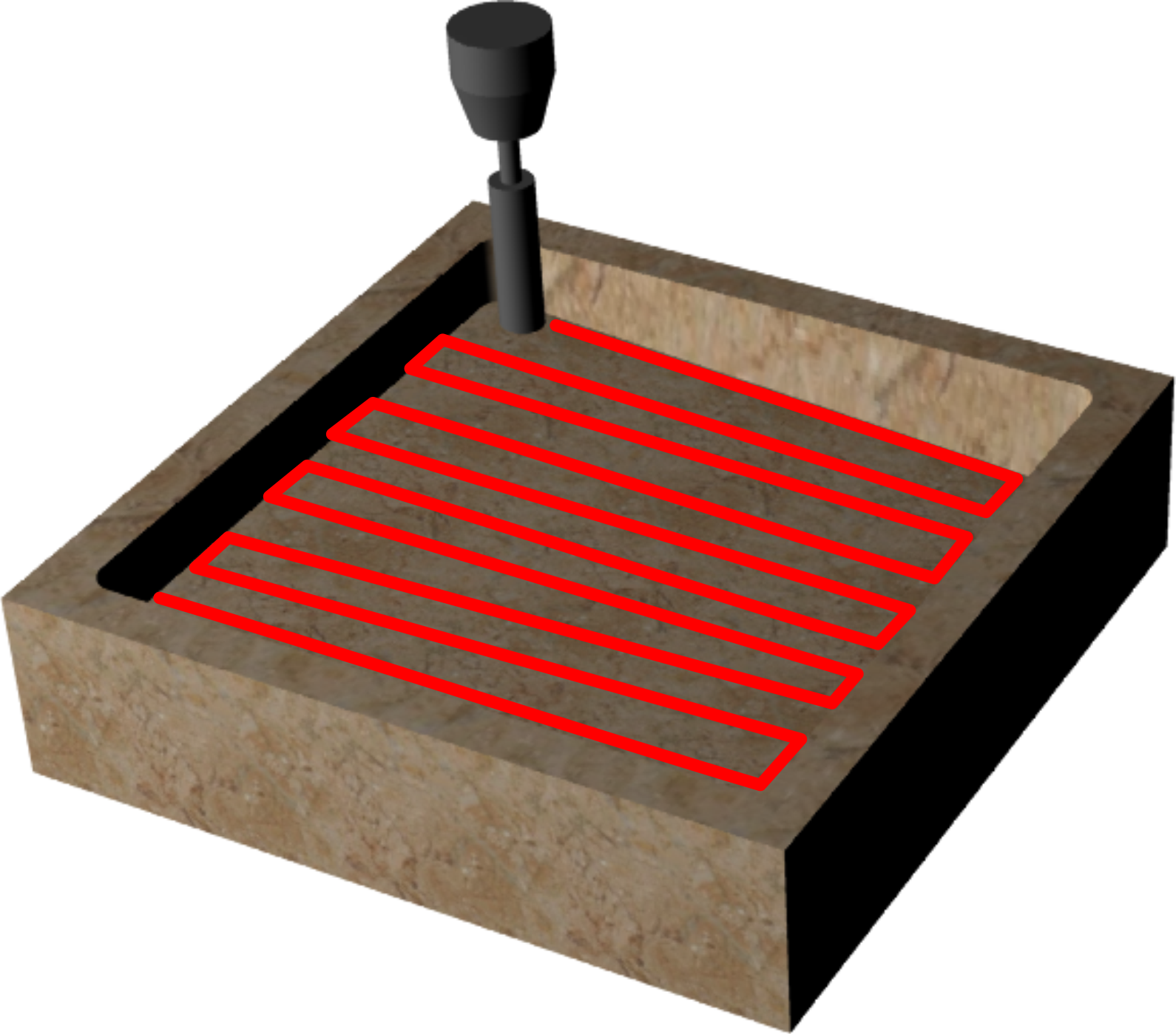 |
 |
||
| | Set drill diameter |  | Space between tool paths | | extra material along inside edge |
| TI: Direction of slope | |||||
| | Depth increase = X increase | | Depth increase = X decrease | | Start depth of slope |
| | Depth increase = Y decrease | | Depth increase = Y increase | | Final depth of slope |
| | If Start depth and Final depth are equal = no slope | ||||
| | HORIZONTAL tool paths along X |  | VERTICAL tool paths along Y |  | SPIRAL tool paths in concentric circles. |
| | VZ = Z- down speed | | VT = Cutting speed | ||
| | SINGLE Depth cut in one stroke. | | STEP Depth cut in several steps. | | Depth increase at each STEP |
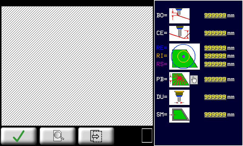
10.2.3.1.3 3D RECESSING
| |  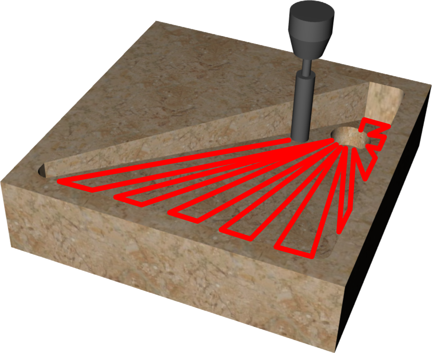 |
|
| |  |
|
| 3D Recessing applied to a rectangle | ||
|---|---|---|
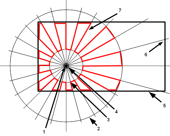 | 1 | Depth at center |
| 2 | Outside radius | |
| 3 | Inside radius | |
| 4 | Drain radius | |
| 5 | Closed object | |
| 6 | Depth at edge | |
| 7 | Tool path | |
| | Set tool diameter | | Depth at edge |  | Depth at drain center |
 | - RE = Outside radius - RI = Inside radius - RS = Drain radius (all at center depth) |  | PB = Cut spacing on edge of slab |  | PR = Cut spacing on outside radius |
 | X position of drain center |  | Y position of drain center | | Extra material along inside edge |
| | Z- down speed | | Cutting speed | ||
11. WORK PROGRAMS
11.1 Run a Program
| | |
|||
| | |
|||
| RUN | |
|||
| |  |
|||
| | |
|||
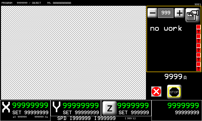
11.1.1 Work Program type 0 (Profili dritti)
 | 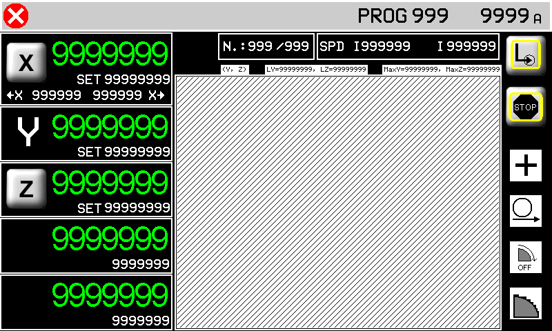 |
| tasto marmo/granito | | STOP | |
| Work Parameters | see Work Program |
 |
 |
| | | | |
 |
|||
| 1 | Auto-set minimum | 2 | Auto-set maximum |
| | The minimum and maximum limits = slab size + disk radius | ||
dimensione blocco??
quota di correzione???
MACHINE START. La successione dei tagli compone la sgrossatura del profilo. L'asse X si muoverà sempre tra le due quote autoapprese che dovranno essere esterne al blocco da lavorare.
A questo punto può essere eseguita la finitura se il selettore della finitura è stato impostato su CONTINUA (se impostato su OFF la finitura verrà saltata, se impostato su SOLO la finitura verrà eseguita subito, senza eseguire la sgrossatura).
Per eseguire l'operazione di finitura la lama si porta sulla quota di X autoappresa minima + quota di correzione e quindi esegue una serie di passate in interpolazione YZ in accordo con i parametri per la finitura impostati. La finitura finisce quando si arriva alla quota X autoappresa massima - quota di correzione (vedi esempio).
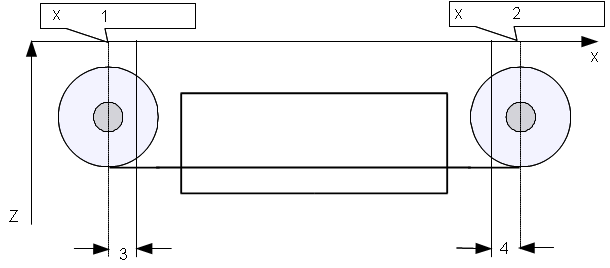 |
|
| 1 | minima autoappresa |
| 2 | massima autoappresa |
| 3 | quota di correzione + |
| 4 | quota di correzione - |
 |
| Sgrossatura, finitura e profilo risultante |
| | Nel dare start al ciclo automatico verrà richiesta un'operazione di azzeramento delle quote degli assi. |
|---|
GRANDE
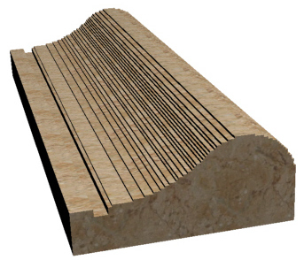
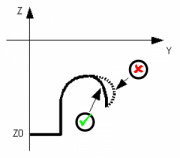
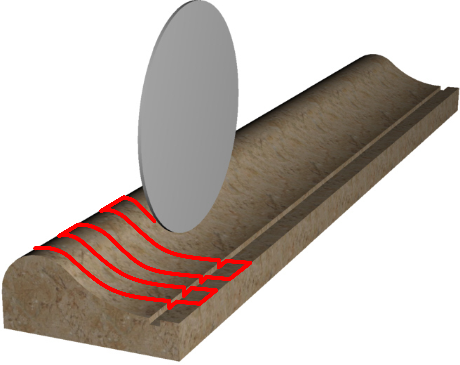
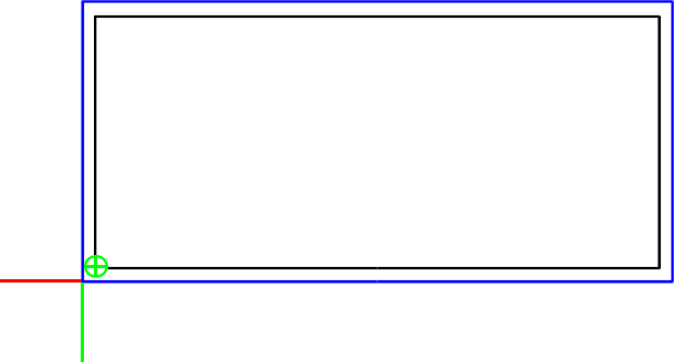
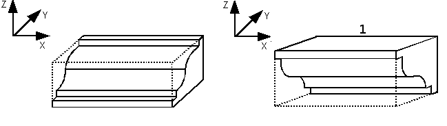
11.1.2 Work Program type 0 (Profili sagomati)
| |  |
I tagli vengono realizzati in successione con un'unica passata (marmo) oppure ad incrementi successivi (granito) in accordo con i parametri impostati in precedenza. La successione dei tagli compone la sgrossatura del profilo. I tagli vengono eseguiti partendo dalla quota X autoappresa minima aggiungendo due tratti orizzontali lunghi come il raggio della lama, prima e dopo il profilo disegnato.
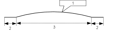 |
|
| 1 | Profile |
| 2 | Disk radius |
| 3 | Profile larghezza |
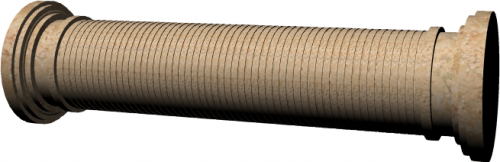
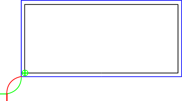
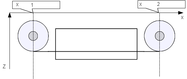
Si potranno presentare quindi due casi:
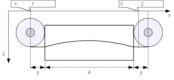 |
|
| 1 | minima autoappresa |
| 2 | massima autoappresa |
| 3 | raggio lama |
| 4 | larghezza del profilo |
In questo caso la larghezza del profilo sommato al diametro della lama è maggiore della distanza tra le due quote di X autoapprese. Come si vede dalla figura, il taglio parte alla quota minima autoappresa e viene eseguito completamente fino a superare la quota X massima autoappresa.
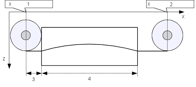 |
|
| 1 | minima autoappresa |
| 2 | massima autoappresa |
| 3 | raggio lama |
| 4 | larghezza del profilo |
In questo caso la larghezza del profilo sommato al diametro della lama è minore della distanza tra le due quote di X autoapprese. Come si vede dalla figura, il taglio parte alla quota minima autoappresa ,mentre il tratto orizzontale finale viene prolungato fino a portare il centro della lama sulla quota X autoappresa massima.
Il processo di finitura non è previsto per le lavorazioni di taglio curvilineo.
Questa schermata spiega che la lama deve essere portata a sfioro del blocco (come rappresentato), prima di dare l' OK per l'azzeramento delle quote degli assi.
 |
| Sgrossatura e profilo risultante |
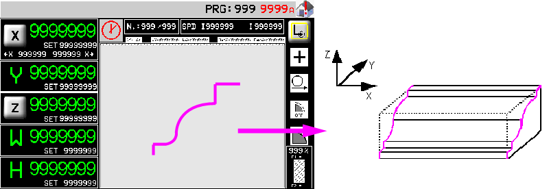
11.1.3 Work Program type 1 or 2 (Profili sagomati)
| |  |
Nella pagina di esecuzione 2D è possibile lanciare l'esecuzione di un programma 2D. Nella lista di lavorazioni sono evidenziate a gruppi di 5 in un menu scorrevole le singole operazioni che compongono il programma. Durante l'esecuzione verrò visualizzata l'esecuzione della lavorazione in maniera simile a quanto ottenuto in fase di programmazione.
| | Nel dare start al ciclo automatico verrà richiesta un'operazione di azzeramento delle quote degli assi. |
|---|
11.1.4 TOPS Work Program
12. ISO G codes
| | |
|
| | |
|
| | Optional accessory requiring QEM Isomanager (see specific manual insert link ) |
|
| | When using an SD card rename the .hex file with a number (0 ~ 999999). (file name: 1.hex, 2.hex…) | |
Program State
| Run Mode | 1: read from SD card read file from a Memory card 2: read from PC read file from the PC connection 3: save on SD card only save file from PC to SD card |
| SD card program number | the .hex file number in the SD card. |
| Read status | the percentage progress of reading the file on SD card. |
| Block Executed | ISO instructions executed. |
| G code of actual line num. | the actual ISO instruction number. |
| G code actual line | the actual ISO instruction. |
Program settings
 | 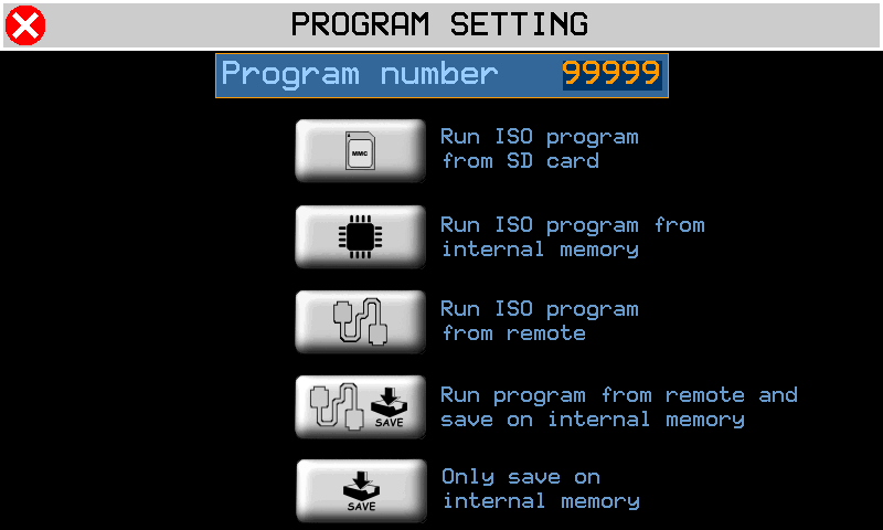 |  | Run ISO from SD card |
 | Run ISO from internal memory | ||
 | Run ISO from remote | ||
 | Run ISO from remote and save on internal memory | ||
 | Only save ISO on internal memory |
13. Alarms
 | 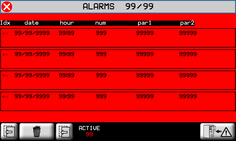 |  cancel all alarms |
Alarms block the machine operation.
| Alarm | Cause | Solution |
|---|---|---|
| Emergency | Manual emergency stop | - |
| Y limit switch backward | Y-axis at minimum LS | - |
| Y limit switch forward | Y-axis at maximum LS | - |
| Z limit switch backward | Z-axis at minimum LS | - |
| Z limit switch forward | Z-axis at maximum LS | - |
| X limit switch backward | X-axis at minimum LS | - |
| X limit switch forward | X-axis at maximum LS | - |
| H limit switch backward | H-axis at minimum LS | - |
| H limit switch forward | H-axis at maximum LS | - |
| Disk not running | Disk must be running in automatic cyle | - |
| Water pressure | No cooling water | The water valve shut |
| Disk motor overcurrent | The disk motor current absorption is over the threshold | - |
| Z Following error | The axis follow error is over the maximum threshold | - |
| Y Following error | - | |
| X Following error | - | |
| Interpolation fault | Error during axis interpolation | One axis over the maximum position |
| Thermic fault | Overload of drivers tripped | - |
| Driver is fault | Fault in one of the axis drivers | - |
| X encoder fault | Axis encoder malfunctioning | - |
| Y encoder fault | - | |
| Z encoder fault | - | |
| W sensor missing | Low table sensor may be disconnected | - |
| Y Axis out of tolerance | Axis positioning out of tolerance | Check axis setup parameters |
| Z Axis out of tolerance | ||
| W Axis out of tolerance | ||
| H Axis out of tolerance | ||
| CAN module - data error | CAN module error | Check CAN comunication or cable |
| CAN module - no comunication | CAN module not responding | |
| SD CARD not present | Error in SD card upload/download | Check the MMC/SD support, check the correct procedure |
| MMC/SD error update | ||
| MMC/SD file not open | ||
| MMC/SD file not create | ||
| MMC/SD error write | ||
| MMC/SD error seek | ||
| MMC/SD error read | ||
| MMC/SD error read seek | ||
| MMC/SD error read format | ||
| MMC/SD error record | ||
| MMC/SD error delete | ||
| MMC/SD error max retry | ||
| MMC/SD undefined error | ||
| INT: motion mode not defined | Interpolation interpreter error | - |
| INT: exact path mode not supported | ||
| INT: invalid istruction | ||
| INT: invalid version | ||
| INT: invalid release | ||
| INT: spindle management | ||
| INT: change tool management | ||
| Mechanical components activation error | Interpolation execution error | |
| INTERP writing error | ||
| INTERP starting error |
13.1 Alarm History
 | 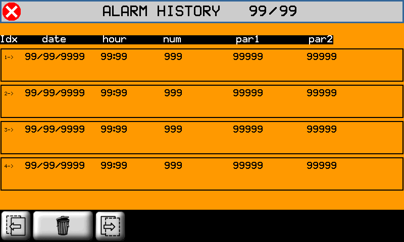 |
to cancel Alarm History
13.2 Warning Messages
Messages do not block the machine operation.
controllare con qpaint
| Messagge | Cause | Solution |
|---|---|---|
| PLEASE WAIT… | Data being processed | - |
| WAITING FOR POWER SYSTEM | | Check the emergency button is not pressed |
| PATH ERROR | There is an error in the path settings, before the process. | The path may be too long |
| DISK TILT ERROR | The disk or tool tilt is not correct for the work cycle | Correct the disk or tool tilt |
| WORK DONE | Automatic cycle is completed successfully | - |
| X POSITION NOT OK | X position is incorrent | X position is outside the auto-set min-max positions |
| RUN HOMING | The Homing is not OK | Run the homing procedure |
14. Diagnostics
| | |
||||
| | |
||||
 PASSWORD:462 |  |
||||
 | I/O |  |
|||
INPUTS  | OUTPUTS  |
||||
COUNTERS  | ANALOG OUTS  |
||||
14.1 CPU DATA
 | Fw name : firmware code and relative checksum Task time : average CPU cycle time Maximum Time and Minimum Time indexing for the scan CPU time : total time CPU is in RUN state (hh:mm) |
14.2 Inputs
| INPUTS  |  | State of digital inputs |
 | Analog input readings | |
 | BOURNS input reading |
14.3 Outputs
| OUTPUTS | | State of the digital outputs. |
14.4 Encoder Counts
| COUNTS | | Axis position  State of encoder channels.  FOLLERR: = realtime following error MAX: POS:/NEG: = min - max follow errors |
|
14.5 Analog outputs
| ANALOG OUTS | | Analog output voltage |
14.6 Controllo dei finecorsa
Controllo dei finecorsa hardware
Controllo dei finecorsa 0° - 90° del disco
 | Disk auto speed table (password) Va su installazione non qui |
Tool compensation limits
The compensazione del tool diameter nelle lavorazioni 2D consente di determinare il percorso che l'utensile di un certo diametro deve compiere per ottenere le dimensioni del pezzo inserite.
Una volta impostato il diametro dell'utensile nella apposita pagina della lavorazione 2D, viene proposto all'operatore il percorso utensile disegnato con un tratto blu. L'operatore deve eseguire un controllo visivo della correttezza del percorso utensile.
Tale controllo è necessario per verificare la correttezza del percorso nel caso in cui si siano verificati i casi limite di seguito elencati:
Percorso utensile che si chiude su se stesso:

This does not cause a tool compensation error.