Indice
~~BOZZA~~
P1P20FK20 - 001 : User Manual

| Document | P1P20FK20-001 | ||
|---|---|---|---|
| Description | Operation | ||
| Drawn up | Michele Sandri | ||
| Approved | Gabriele Bazzi | ||
| Link: | http://www.qem.eu/doku/doku.php/en/strumenti/qmoveplus/j1p20/mdu_p1p20fk20-001/setup_-_tarature_-_funzionamento | ||
| Languages | English - Italiano | ||
| Release | Description | Notes | Date |
| 01 | New Manual | 10/04/14 | |
All rights reserved on this manual. No part of this document can be copied or reproduced in any form without prior written authorisation. QEM does not insure or guarantee its contents and explicitly declines all liability related to the guarantee of its suitability for any purpose. The information in this document can be changed without notice. QEM shall not be held liable for any error or omission in this document. QEM® is a registered trademark.Microsoft® and MS-DOS® are registered trademarks and Windows® is a trademark of Microsoft Corporation.
Contents
-
HMIWork Programs
Description
The P1P20FK20 - 001 application software installata on the hardware Qmove J1-P20-FK20, is a controller for marble edging machinery with a maximum of 14 heads, providing the possibility to control the startup of the head motors and eventual movement of a floating system. Each head can be given an advance/lag on the start and end of the piece.
Main characteristics
-
Touchscreen buttons to enter data and operations
-
Program edit and run screens
-
Independent on/off for each head
-
Alarm and warning messages
-
Cancel functions on all or only selected pieces
HMI
Standard Buttons
-
Yellow settings can be modified. Press to change, use the keypad to enter a setting.
-
 Select multiple choice parameters.
-
 Confirm parameter setting
-
 Go to previous screen
-
 or
or  Change screen
Function keys
Function key Led Function Hardware 
- Main Menu J1P20-FK20 
- Manual operations 
- Program select 
- Reset pieces 
- Diagnostic 
- Alarms screen 
- Previous screen
Press 1 second for Main screenTop and Bottom Bars

The Top Bar: . Machine state . . Screen name . . Time . Machine states
State Icon Description INITIALISING 
Machine startup, loading data MANUAL 
Machine in manual mode SETUP 
Machine in setup (reserved area) PROGRAMMING 
Machine in program edit AUTO ON 
Machine in automatic mode ALARM 
Machine in alarm mode The Bottom Bar: Red bar: most recent alarm Blue bar: warning messages Warning Messages
Message Description Too many pieces in machine Too many pieces are on the conveyor (>30).
Stop the piece feed to allow the machine work the pieces already loaded.Waiting for power system… The machine is waiting for the power system to be ready before quiting the initializing state Zero floating system on Searching for the zero position of the floating system Zero floating system timeout The set time to search for the floating zero has expired Start Screen

The machine will wait until the power system is ready before going to the main screen Progress messages are given during this time.
Main screen
Name Description Program N°: Program number and description of work in progress. Conveyor speed Conveyor speed in m/min. Floating Floating system On/Off. Worked Mt Total material worked by the machine in metres. Worked Pcs Total pieces worked by the machine. Last Pc Length Length of the last piece to enter the machine. 
 and
and  to go from one main screen to another:
Main Screen 2
The screen format depends on the machine layout:
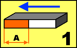
 = machines with piece feed from left
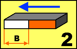
 = machines with piece feed from right
Display showing heads working, conveyor movement and speed, the piece infeed sensor state and the mandrel motor states.
Heads ON/OFF Utility
A shortcut panel to control the heads:


Head on

Head offMenu


Button Description 
Alarm screen 
Programming screen 
Functions menu 
Input/Output Diagnostic menu 
Reserved area (password needed) Work Programs


Touch a program to select it.


Scroll the program list 
Mark the program to work 
Open the program to edit it Program editing

A work program includes: • Mandrel work parameters
• Bevel work parametersSteps to edit a work program:

 Bevel programming screen:

Touch a program name to change it.
Select if the program is for all heads or a single head:
Button Description  : Uniform setting
Mandrel/Bevel program parameters valid for all Mandrels/Bevel on machine.
The Head number scroll cannot be used and
and Change the Head number -
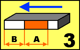
the diagram on the left and select the work type, according to the head type.
-
and set
 and
and  according to the parameters requested in the diagram.
 -
 is the work area, WHITE is the no work area
WORK 1
 for Mandrels
 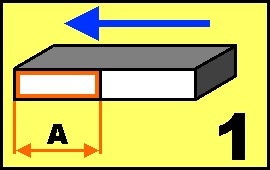 for Bevels
WORK 2
 for Mandrels
 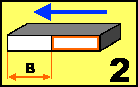 for Bevels
WORK 3
 for Mandrels
 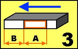 for Bevels
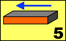
WORK 4
 for Mandrels
 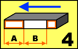 for Bevels
WORK 5
 for Mandrels
  for Bevels
When exiting the screen, confirm to save the program :
 .
.
Functions menu


manual/automatic

Homing of Floating

Reset pieces
Manual/Automatic


MANUAL

AUTOMATICManual


Functions in this screen:-
Move conveyor by manual jog (only if implemented)
-
Move the floating system by manual jog (only if implemented)
-
Command each head up/down and motor start
To operate a movement, select the touch buttons for the function and press Start. MODE indicates indicate the manual operation mode:
-
PULSE = keep Start pressed to operate the function, release to stop (standard)
-
CONTINUOUS = press Start to operate the function, press to stop
MANUAL Screen 1: conveyor and floating system
Button Description CONVEYOR 

Select forward or backward jog direction. The real speed is given in m/min FLOATING SYSTEM Select jog movement of the floating system MANUAL Screen 2: head up or down and motor start

-
Select a head
Button Description 
Select UP for selected head 
Select DOWN for selected head 
Select OFF for the selected head motor 
Select ON for the selected head motor The diagram next to the buttons shows the state of the selected head.
In manual mode the heads are disabled. If a piece is fed into the machine, it is detected but not worked.
Homing of floating system

Start ZERO homing procedure on the floating system
Description
1 - the floating system is operated until the zero sensor input is not received once
2 - the second time the sensor is tripped, a timer is started equal to the time from the previous input plus a setup parameter
3 - when the timer ends, which should correspond to a full cycle of the floating system, a control checks that the system is at the zero sensor
4 - if the system stops before or after the sensor, the homing starts again, increased or decreased by a the time, plus or minus a setup parameter
5 - the cycle is repeated until the system stops exactly on the zero sensor
6 - Each cycle is delayed for a set time.
Reset pieces


Reset all pieces

Reset selected pieces
Reset all pieces


Reset all pieces
★ Wait 2 sec.

No Reset
Quit screenReset selected pieces
 -
- 
 -
-

Parameter Unit measure Description IN WORK - How many pieces are loaded in the machine SELECTED - How many pieces have been selected for cancellation 

- Forward and back through the piece data screens. If a screen does not have pieces it is not shown PIECE - The piece number loaded. Touch to select or unselect QI:Start position mm The distance from the piece read sensor and the front of the piece QF:End position mm The distance from the piece read sensor and the end of the piece L:Length mm Length of the piece HEADS - The two heads at the front and end of the piece. An empty space between two heads is indicated by <> next to it
Button Description 
Confirm selection and go to reset screen
Reset selected pieces
★ Wait 2 sec.
No Reset
Quit screenDiagnostic


Digital Inputs Diagnostic


The LED is on when the input is active
Digital Output Diagnostic


The LED is on when the output is active
Encoder Counts Diagnostic


Z IN led shows the Z input state (zero pulse).
Conveyor Analog Out Diagnostic


The analog output is given in Volts.
CANbus Network Diagnostic


Canbus Monitor
System Information


Fw name firmware and checksum Aux fw I/O module firmware ( only if implemented ) Task time CPU cycle time : Minimum, Average, Maximum CPU time CPU time in Run state (hh:mm) Touch screen Test touch Alarms
The Alarm messages are given in the screen below:


Alarm Message Cause Emergency pressed The emergency is pressed and the machine disabled Inverter fault An inverter fault has been detected Conveyor encoder fault No signals from conveyor encoder input. Thermal cutouts Check the circuit breakers in the electric cabinet Enclosures open Check that all enclosures are closed No air heck the compressed air circuit Can Bus Error Can network error (only if implemented) Can Node Guarding Can node detection error (only if implemented)  Can module disconnected

To cancel an alarm :
★ eliminate the cause
★ press the button for 3 seconds
Alarm history listing:
 →
→ 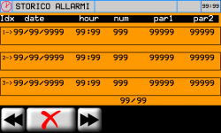
★ To cancel the alarm history
eliminate the causes
★ press the button for 3 seconds
N.B. Alarm history maximum = 60Aftersales Service
Shipment Pack the controller adequately to avoid knocks and crushing during transport.
A good packing will avoid future problems.Enclose:
-
The serial number of the machine mounting the controller
-
A description of the fault
-
Controller program data (e.g. setup, work distances, parameters, etc)
A detailed description with allow a rapid identification and solution to the problem.


