Inhaltsverzeichnis
P1P20FH20 - 001 : Installation Manual

| Document | MDI_P1P20FH20-001 | ||
|---|---|---|---|
| Description | Installation Manual | ||
| Drawn up by | Michele Sandri | ||
| Approved by | Gabriele Bazzi | ||
| Link | http://www.qem.eu/doku/doku.php/en/strumenti/qmoveplus/j1p20/p1p20fh20-001/mdi_p1p20fh20-001 | ||
| http://www.qem.eu/doku/doku.php/strumenti/qmoveplus/j1p20/mimj1p20fx | |||
| Language | English | ||
| Document Release | Description | Notes | Date |
| 01 | New manual | 07/07/2014 | |
All rights reserved on this manual. No part of this document can be copied or reproduced in any form without prior written authorisation. QEM does not insure or guarantee its contents and explicitly declines all liability related to the guarantee of its suitability for any purpose. The information in this document can be changed without notice. QEM shall not be held liable for any error or omission in this document. QEM® is a registered trademark.Microsoft® and MS-DOS® are registered trademarks and Windows® is a trademark of Microsoft Corporation.
Contents
-
1.Description
-
2. Hardware J1-P20-FH20
-
2.1. Standard Symbols & Buttons
-
2.2. MAIN SCREEN
-
3. Startup
-
4. Setup
-
4.1. HMI Setup
-
4.2. General Parameters - GP
-
4.3. Machine Parameters - MP
-
4.4. Belt and Head Calibrations
-
4.5. Calibration
-
4.5.1. Belt resolution
-
Axis Resolution
-
4.5.2. Maximum Belt Speed calibration
-
4.5.3. Head Calibration
-
4.5.4. Slab IN limit switch offset
-
4.5.5. Dynamic head Up/Down correction
-
5. Diagnostic
-
5.1. Digital Input diagnostic
-
5.2. Digital Output diagnostic
-
5.3. Operating Diagrams
-
5.4. Belt encoder count
-
5.5. Analog Inputs and Outputs
-
5.6. System Info
-
6. Warnings
-
7. Alarms
-
7.1. Alarm list
-
7.2. Alarm history
-
8. Typical wiring diagram
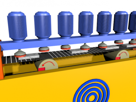
1. Description
Il software P1P20FH20 - 001, installato nell'hardware Qmove J1-P20-FH20, realizza l'automazione di macchine levigatrici/levigabordi .
Caratteristiche principali
-
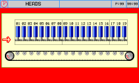
lo strumento comanda 19 teste di lavoro
-
controlla l'avviamento sequenziale dei motori (per limitare l'eccessivo richiesta di corrente )
-
gestisce l'eventuale spostamento del ponte
-
per ogni testa di lavorazione è possibile impostare gli anticipi e i ritardi di lavorazione, sia all'inizio, sia alla fine del pezzo
-
I comandi di salita/discesa delle teste di levigatura, vengono calcolati automaticamente al variare della velocità del nastro trasportatore.
-
lo strumento conta i metri lavorati ed è in grado di lavorare fino a 30 pezzi presenti contemporaneamente in macchina.
Altre Caratteristiche
-
HMI con touchscreen
-
Tasti funzione
-
Programmi di lavoro
-
Messaggi di allarme
-
Messaggi di warning
-
Reset dei pezzi difettosi
-
Reset di tutti i pezzi in lavorazione
-
Compensazione dell'offset del finecorsa di presenza pezzo
-
Modo di lavorazione delle teste
-
Levigatura
-
Fresatura
-
Molatura
-
Spazzolatura
-
Getto d'acqua
Opzioni e caratteristiche di possibile futura implementazione
-
Con l'installazione dei moduli RMC1XX sarà possibile automatizzare 2 o 4 calibratori
-
Con l'installazione dei moduli RMC1YY sarà possibile leggere la corrente di ogni testa
-
E' possibile dotare lo strumento del software necessario per realizzare delle lavorazioni di bocciardatura
-
E' possibile dotare lo strumento di funzionalità software di abilitazione/disabilitazione di ogni singola testa
-
E' possibile dotare lo strumento di porta Etnernet, che consente di trasmettere i dati della macchina agli uffici di programmazione della produzione .
-
Risparmio energetico : accensione dei motori solo durante la lavorazione
Nota : in questo caso si dovrà utilizzare un modulo di espansione degli I/O
Note Se il cliente è interessato a queste opzioni e caratteristiche, oppure altre di Sua scelta, contattare l'Ufficio Commerciale della QEM ( info@qem.it )
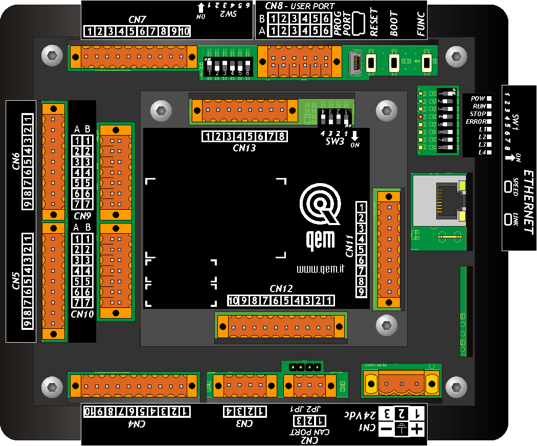
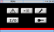
2. Hardware J1-P20-FH20
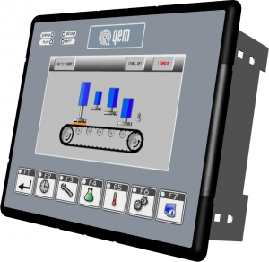

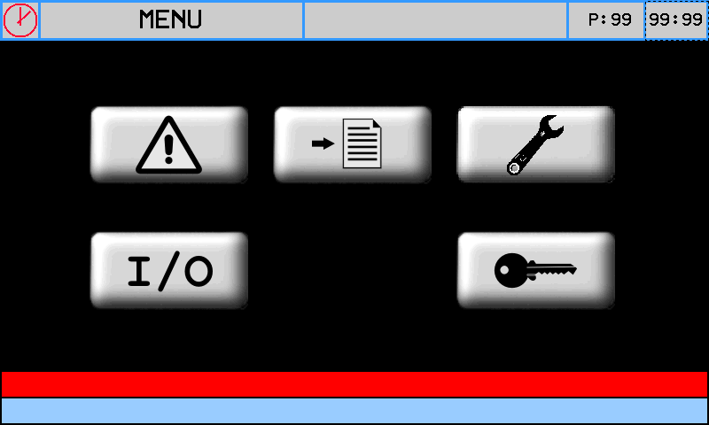
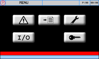
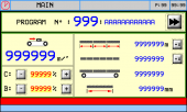
MAIN MENU 
RESERVED SETUP (enter password) 
WORK PROGRAMS 
RESET ALL SLABS 
RESET SELECTED SLABS 
ALARMS 
ESC TO PREVIOUS SCREEN

2.1 Standard Symbols & Buttons
Button Description ———————– Top Bar Symbol Description 
Confirm Popup entry 
Manual 
Popup Select 
Alarm  ..
..
Previous screen & Next screen 
Automatic  ..
..
Scroll list 
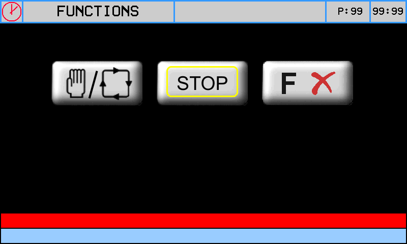
Function mode 
Reserved Area 
Not initialized 
Quit without saving 
Setup Locked/Unlocked 
Confirm setting 
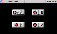
Calibration 
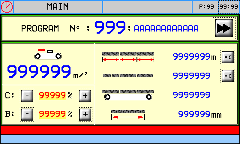
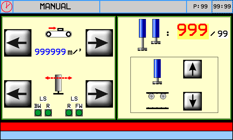
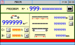
Green settings can be changed - - - - - - - - - - - - - - - - - - - - - - - - - - - - - - - - - - - - - - - - - - - - - - - - - - - - - - - - - - - - - - - - - - - - - - - - - - - - - - - - - - - - 2.2 MAIN SCREEN


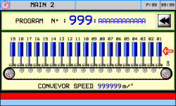 Right IN
Top Bar (grey)
- Machine State
- Page name
- Page number
- Time
Bottom Bars
- Alarms (red)
- Warnings (light blue)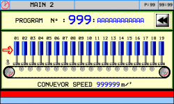 Left IN
3. Startup
Important
hardware, wiring, general info, system info: Hardware manual ★Per una corretta messa in funzione della macchina, si raccomanda di seguire l'ordine delle attività di seguito descritte e illustrate
-
Control the application software code in the Start screen
-
Controllare la funzionalità del Touch in HMI Setup
-
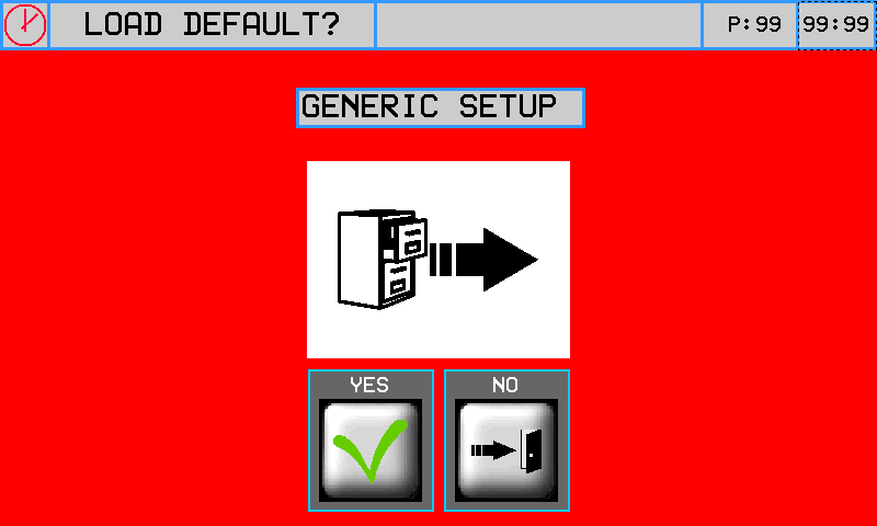
Load the Default Parameters
-
Control the General Parameters - GP and Machine Parameters - MP
-
Check the wiring in Diagnostic (see Typical Wiring Diagram)
-
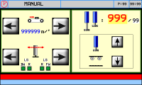
Check the Beam direction forward/backward in the Manual screen
-
Go to Calibration
-
Check the count direction and calibrate the Belt resolution in Belt Resolution
-
Calibrate the Maximum Belt Speed Calibration
-
Calibrate the Slab IN limit switch offset
-
Calibrate the Head Calibration
-
Work diameter
-
Set the head distances from the slab IN limit switches
-
Set the Dynamic head Up/Down correction to the Belt speed
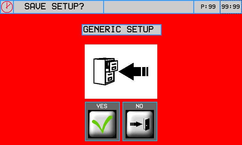
Carry out the Backup ProcedureCarry out the Archiving Procedure4. Setup


PASSWORD:462 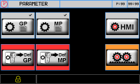


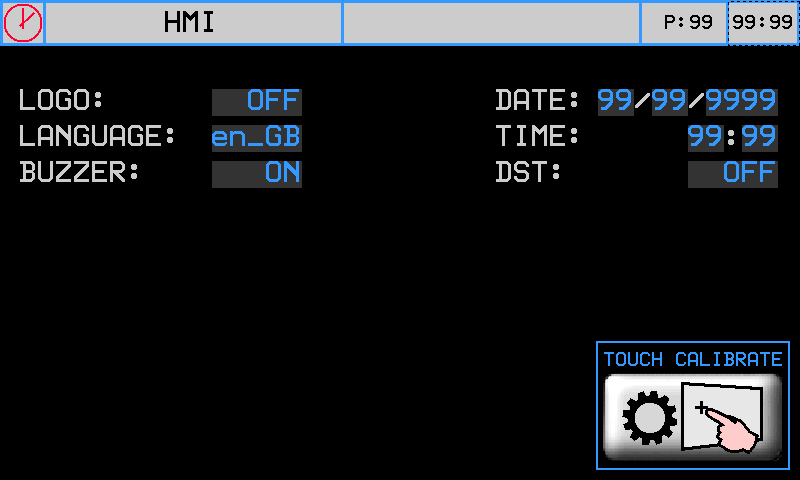
4.1 HMI Setup

PASSWORD:462 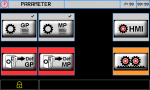

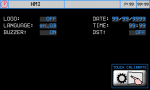


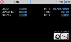
Parameter Default Range Description LOGO ON OFF ~ ON OFF: No logo
ON: logoLANGUAGE en_GB - en_GB : English
it_IT : ItalianoBUZZER ON OFF ~ ON OFF: no buzzer
ON: buzzerDATE - - Set the date TIME - - Set the time GMT TIME OFF OFF ~ ON OFF: no legal time
ON: legal time
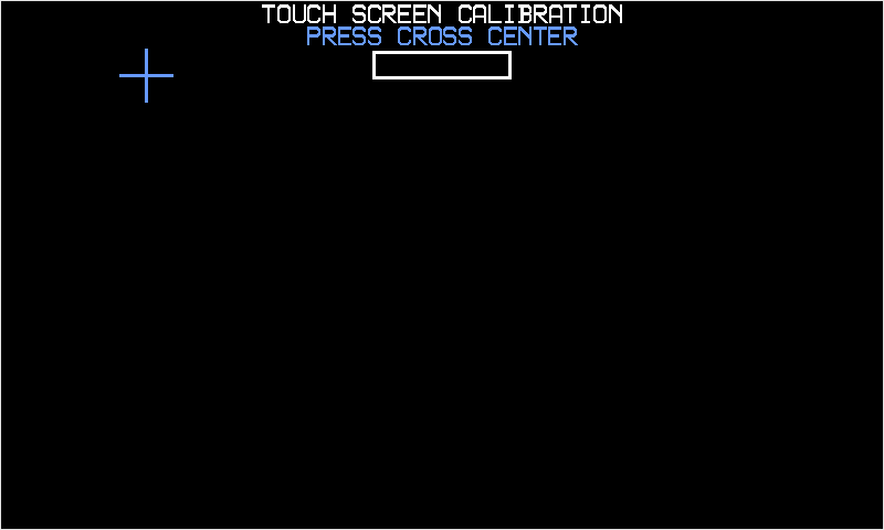
Touch Screen calibration

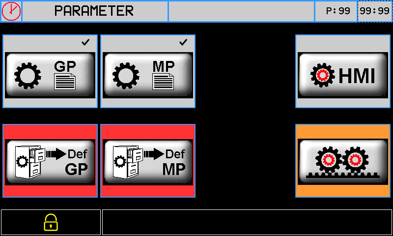
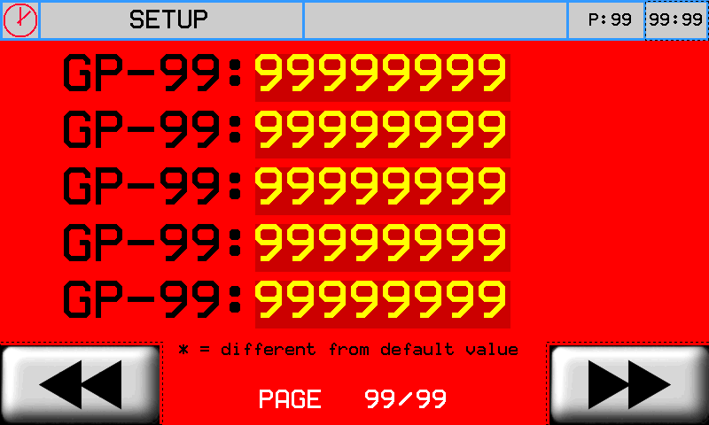
Keep + pressed until bar is full 4.2 General Parameters - GP

Parameter U.M. Default Range Description GP-01 - 4000 P ( Pulse ) Encoder pulse reading x 4, corresponding to length in Measure . GP-02 - 400.0 M ( Measure ) Length corresponding to encoder pulses (Pulse)
- P/M is the resolution. It must be 0.000935 ~ 1.000000.
- Pulse ane Measure are set by the procedure Axis Resolution.GP-03 - 1 0 ~ 3 Decimal point for Belt speed
0=xxxx, 1=xxx.x, 2=xx.xx, 3=x.xxxGP-04 - 0 0 ~ 1 Decimal point for Belt misura
0: xxxx, 1: xxx.xGP-05 - 1 0 ~ 1 Heads Position at belt speed below the minimum (GP-06 )
0 = heads remain DOWN .
1 = heads go to UP .GP-06 - 0.1 0 ~ 999999 Minimum Belt speed GP-07 - 0.5 0 ~ 999999 Speed Delta, when above the filter is applied ( GP-08 ). GP-08 msec 50 0 ~ 9999 Filter on Belt speed GP-09 - 0 0 ~ 5 Sampling Time of the frequency meter
(used to determine the belt speed)
0 = 240 ms,
1 = 480 ms,
2 = 24 ms,
3 = 120 ms,
4 = 960 ms,
5 = 1920 ms.
GP-10 - 0 0 ~ 1 0 = Save slabs when machine OFF
1 = Do not save slabs when machine OFFGP-11 - 0 0 ~ 1 Slab IN (input I09) below minimum speed .
0 = YES
1 = NOGP-12 mm 10.0 0 ~ 9999 Distance, if below two adjacent slabs are worked in continuous
The slab counter still counts 2 slabsGP-13 msec 1000 0 ~ 9999 t1 time for motor start output GP-14 msec 1000 0 ~ 9999 t2 time between one motor start and another GP-15 msec 1000 0 ~ 9999 t3 time between the last motor start and O24 output for end of motor start sequence GP-16 - 0 0 ~ 1 Abrasive Change Position
0 = on backward LS
1 = on forward LSGP-17 - 0 0 ~ 1 Enclosures contact logic
0 = NC
1 = NO4.3 Machine Parameters - MP

Parameter U.M. Default Range Description MP-01 - 1 1 ~ 19 Number of heads MP-02 mm 0 0 ~ 999999 Machine length
Distance between the slab IN limit switch and end of the machineMP-03 - 0 0 ~ 4 Belt Command/Control
0
- External Command/Control
- speed reading
1
- Command
- speed reading
- analog out
2
- Command
- speed reading
- analog out (set by potentiometer).
3:
- Command & Control by encoder feedback
- speed reading
- analog out
- Start/Stop from controller
4:
- Command & Control by encoder feedback
- speed reading
- analog out (set by potentiometer)
- Start/Stop from controllerMP-04 - 0 0 ~ 1 Beam Command
0 = External Control.
1 = Beam Control with min & max limit switches and slowdown
(Il movimento avviene con almeno un pezzo in macchina).MP-05 - 0 0 ~ 1 Motor Start Sequence .
0 = NO
1 = yesMP-06 - - - - MP-07 - - - - MP-08 m/min 5.0 0 ~ 5.0 Maximum Belt speed ( AO1 = 10 Volt ) (MP-03 > 0) MP-09 m/min 3.0 0 ~ 5.0 Max Belt Speed in automatic
(MP-03 > 0 )MP-10 m/min 1.0 0 ~ 5.0 Belt Jog speed
( MP-03 > 0)MP-11 - 0 0 ~ 1 Beam start mode in automatic ( MP-04 = 1).
0 = Start with belt
1 = Start when slab INMP-12 s 1.000 0 ~ 999.0 Tempo di ritardo tra la Belt start and Beam start (MP-05 = 1) MP-13 % 5.0 0 ~ 100.0 % maximum speed of Beam in automatic MP-14 % 5.0 0 ~ 100.0 Slow speed of Beam in automatic (MP-04 = 1) MP-15 % 50.0 0 ~ 100.0 Jog speed of Beam (MP-04 = 1) MP-16 s 2.000 0 ~ 999.0 Beam stop time at max & min limit switches ( MP-04 = 1) MP-17 - 0 0 ~ 1 Slab IN Direction
0 = right
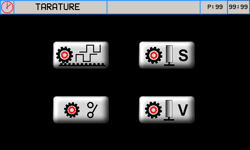
1 = left4.4 Calibration
PASSWORD:462


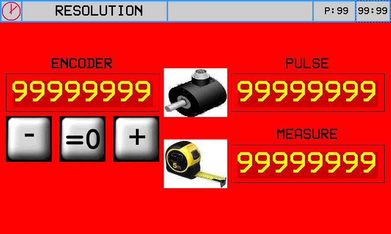
4.4.1 Belt resolution
→ 
Procedure
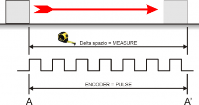
-
Press
 and check the ENCODER box increases(Analog out +1 Volt)
 -
Press
 and check the ENCODER box decreases (Analog out -1 Volt)
 -
A - A' = The maximum space
-
Take note of the start position (A)
-
Zero-set the ENCODER:

-
Move the axis from A to A'
-
Take note of the reading in ENCODER box and write it in the PULSE box
-
Measure the distance from A to A' = space delta
-
Enter the A - A' space delta in the MEASURE box
Important:
-
PULSE must alway be greater than MEASURE (the best is „MEASURE x 10 = PULSE“)
-
Enter MEASURE in the selected unit measure. E.G. if a unit measure of 1/10mm is selected and the space delta is 133.5mm, enter 1335 in the MEASURE box
4.4.2 Maximum Belt Speed calibration
Set the same speed in MP-08 and MP-10 


 start the belt
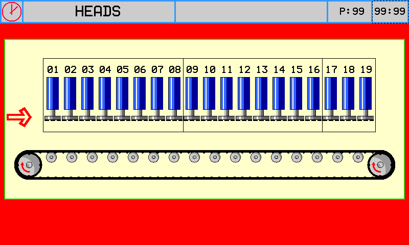
 Take note of the speed Set the speed in MP-08 Set MP-09 and MP-10 as required 4.4.3 Head Calibration
 OR
OR 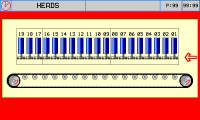
MP-16 = Slab infeed direction head group box

 -
-  -
- 
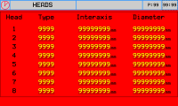
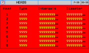
Parameter U.M. Default Range Description Type - - 0 ~ 5 Head function modes
0: OFF
1: Polishing
2: Milling
3: molatrice
4: Brush
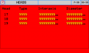
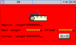
5: Air/water jetInteraxis mm - 0 ~ 99999.0 Distance from slab IN limit switch to the head center Diameter mm - 0 ~ 99999.0 Work diameter 4.4.4 Slab IN limit switch offset
-
Measure the length of a slab and enter in Real length
-
Start the belt so the controller reads the slab length by the slab In limit switch
-
Measur. length gives the length reading
-
 to set the limit switch offset
 -
The offset can also be changed manually
-
Correc. Length shows the new corrected length
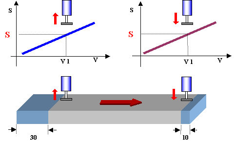
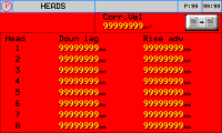
4.4.5 Dynamic head Up/Down correction

set all motors to OFF 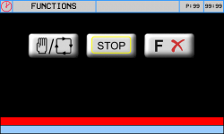

OR MP-16 = Slab infeed direction head group
 -
-  -
- 
Parameter U.M. Default Range Description SPEED CORR. m/min 3.0 0 ~ 5.0 Reference speed for Dynamic calibration Down lag mm - -999.0 ~ 999.0 ( + ) Delay distance for head DOWN on slab front . Rise adv mm - -999.0 ~ 999.0 ( + ) Advance distance for head UP before slab end . Copy settings to all heads A Typical example 
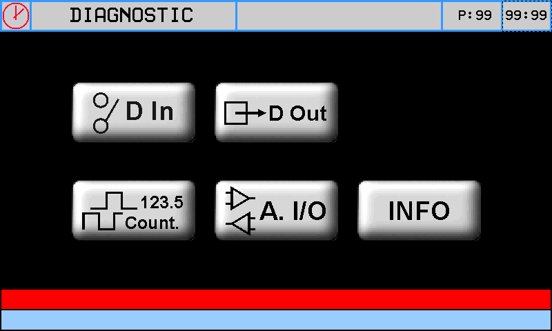
To Polish ALL the slab at V1 = 3 m/min, set Downlag = 10, Rise adv = - 30 The lags and advances for other speeds are calculated automatically 5. Diagnostic

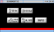

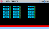


5.1 Digital Input diagnostic


INPUT NAME LOGIC DESCRIPTION I01 Emergency NC - O Stop with Alarm message I02 Not used - - I03 Start motors NO - C Start motor sequence con MP-05 = 1 I04 Power system enabled NO - C Machine ready - I05 NE NC - O In automatic, stop beam and belt /Reset the „motor rotation startup error“ message - I06 Overload cutouts NC - O Chain of overload cutouts with Alarm message I07 Enclosures NC - O Chain of enclosures I08 Air pressure switch NC - O No air I09 Slab IN NO / C Limit switch for slab length acquisition I10 Not Used - - I11 Not Used - - I12 Inverter fault NC - O Inverter alarm with Alarm message I13 Beam Forward LS NC - O Beam forward limit switch with fast speed con MP-04 = 1 I14 Beam Backward LS NC - O Beam backward limit switch with fast speed I15 Beam Forward Slow LS NO - CC Beam forward limit switch with slow speed I16 Beam Backward Slow LS NO - CC Beam backward limit switch with slow speed Note
★ NC - O = Normally Closed contact, action when the contact Opens
★ NO - C = Normally Open contact, action when the contact Closes
★ NO - CC = Normally Open contact, action when the contact Closed in Continuous
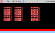
5.2 Digital Output diagnostic


N° DESCRIPTION O1~O19 Head UP/DOWN and motor start commands O20 Belt direction
- OFF forward
- ON backwardO21 Beam direction
- OFF forward
- ON backwardO22 Water valve output O23 Trips when slabs < 30 in machine (upline machine consensus) O24 Machine OK output 5.3 Operating Diagrams
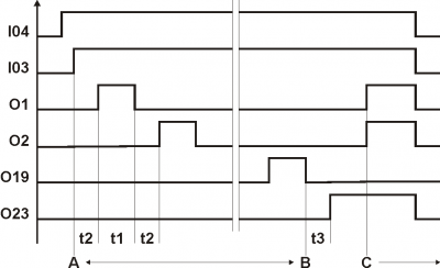
-
t1 one motor start time
-
t2 time between one motor start and another
-
t3 at end of motor starts(O19 = OFF), wait t3 time for O23 = ON
-
O23 = ON end of motor starts and OK to start loading slabs upline
-
A - B start head motors time
-
C time before machine is ready for work
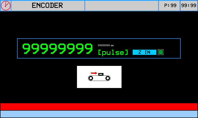
5.4 Belt encoder count
N° NAME DESCRIPTION PHA1/PHB1 Belt encoder signals - to measure the slab lengths and establish their position on the belt
- measure the feed speed of the slabs and calculate the head Up/Down advances - delays

Note:
• Z_INP led signals the Z pulse input state (not used in this application).
• Pulse : Encoder pulses x 4
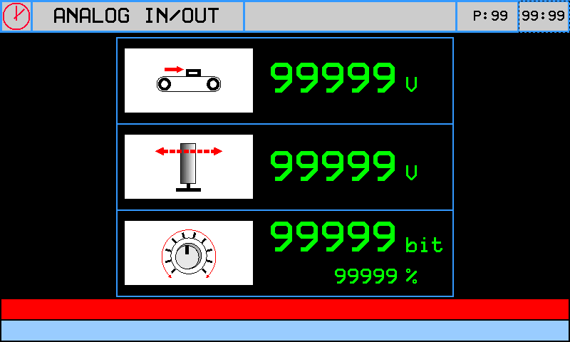
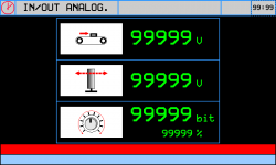
5.5 Analog Inputs and Outputs
N° NAME DESCRIPTION AI1 Analog input, belt speed variation (analog out AO1). Potentiometer input.
Reading in bit and percentageAO1 Out 0~10 Volt Inverter command Belt AO2 Beam 
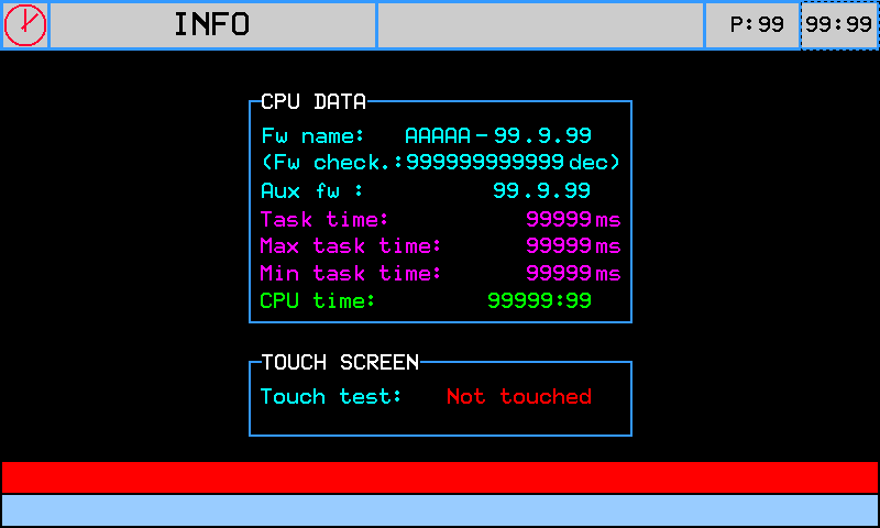
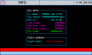
5.6 System Info
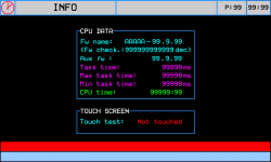
Fw name firmware and checksum names Aux fw I/O module firmware (not used in this application Task time CPU cycle time: Minimum, Medium, Maximum CPU time CPU run time (hh:mm) Touch screen Test touch 6. Alarms


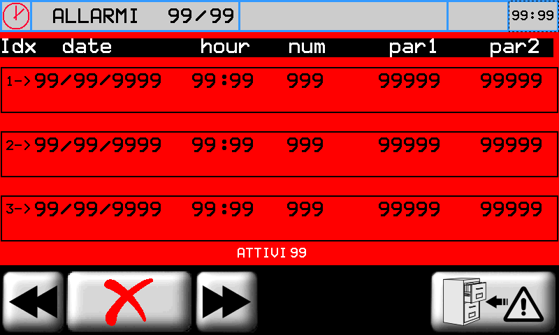
6.1 Alarm list


To cancel alarms
- eliminate the cause
- press for 3 seconds.
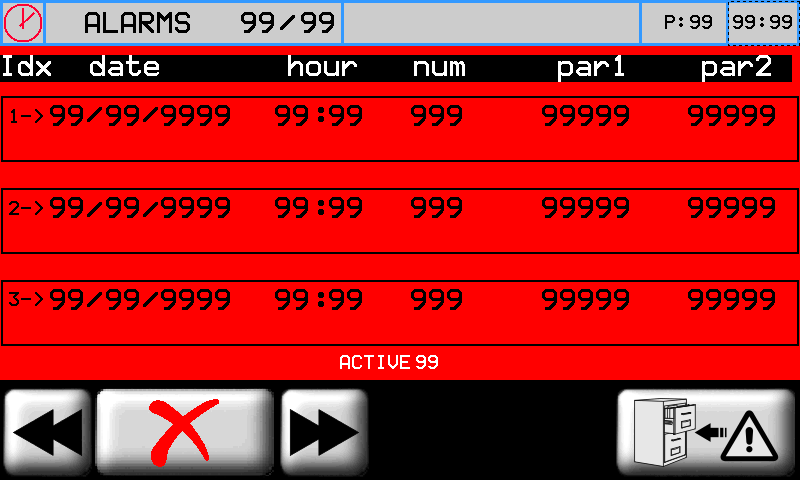
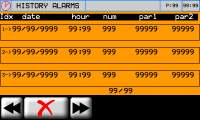
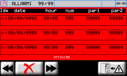
Message Cause Input Emergency pressed Check the emergency button and line I01 Inverter fault Control the inverter I12 Belt encoder fault Control the belt encoder (Acive only with MP-03 > 2). Overload cutouts Check the overload cutouts I06 Enclosures Check the enclosures I07 No air Check the air pressure switch I08 the Belt encoder fault alarm trips automatically if the belt moves less 2 u.m. in 5 seconds (less than 60 mm/min) 6.2 Alarm history

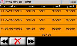
To cancel alarms
- eliminate the cause
- press for 3 seconds Maximum 60 alarms 7. Warnings
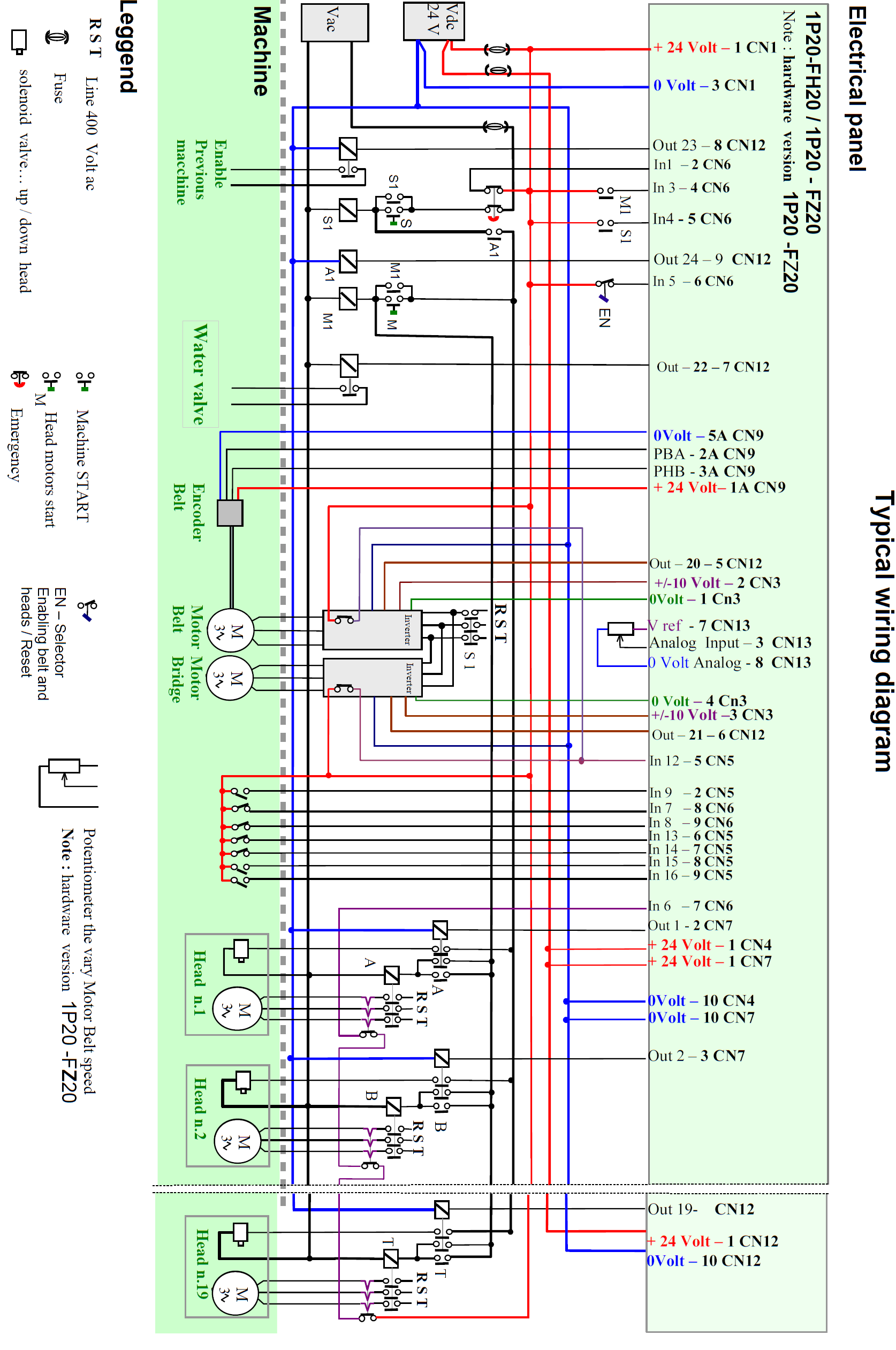
Message Description Too many slabs in the machine There are more than 30 slabs in the machine Waiting for power system… Waiting for the power system to startup (MP-08 enabled)(I04 = ON ) Going to change abrasive position… The beam has been commanded to move to change abrasive Power system disabled Power system disabled (I04 = OFF). Caution Motors off Belt start attempted with motors off 8. Typical wiring diagram

-
-
-