Table of Contents
Multi-head Polishing machine: Installation

| Document | P1P51FC20-008Q | ||
|---|---|---|---|
| Description | Connections | ||
| Drawn up | Riccardo Furlato | ||
| Approved | Gabriele Bazzi | ||
| Link: | http://www.qem.eu/doku/doku.php/en/strumenti/qmoveplus/j1p51/mdu_p1p51fc20-008/connections | ||
| Languages | English | ||
| Release | Description | Notes | Date |
| 01 | New Manual | 31/07/14 | |
All rights reserved on this manual. No part of this document can be copied or reproduced in any form without prior written authorisation. QEM does not insure or guarantee its contents and explicitly declines all liability related to the guarantee of its suitability for any purpose. The information in this document can be changed without notice. QEM shall not be held liable for any error or omission in this document. QEM® is a registered trademark.Microsoft® and MS-DOS® are registered trademarks and Windows® is a trademark of Microsoft Corporation.
Description
The P1P51FC20 – 008Q application, installed on the Qmove+ J1-P51-FC20 and Remote I/O modules RMC-2M, has been designed to control a marble slab polishing machine with mobile beam.
Salient Features of the control
-
Control of 2 axes in analog (beam + belt)
-
Control of up to 24 heads (depending on hardware)
-
Control of accessories (brush, sprays)
-
Slab sizing by Sensor bar
-
Abrasive wear control and statistics
-
Head pressure control with work programs
-
Touchscreen functions for data settings and actions by buttons
-
Staggered motor startup
-
Operator help messages
-
Alarm messages
1. Hardware
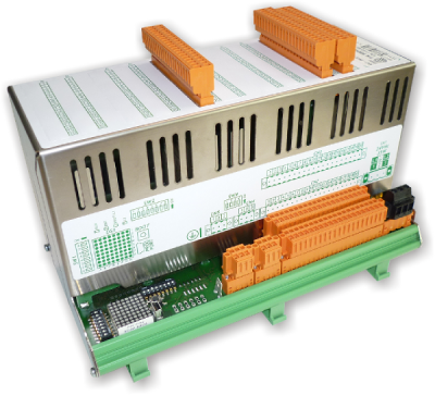
Operator Panel
| J1-P51-FC20/TP03 |
|---|
 |
 |
Remote modules inputs/outputs
| [1] Cabinet :RMC-2MC01-D2/I32/I32/I32/0/0/24V [2] Beam :RMC-2MC01-G6/A12/A12/G12/G12/P32/24V |
|---|
 |
 |
1.1 I/O Resources
1.1.1 Digital Inputs (n. 109)
| Name | Description | Logic | Terminal | Terminal Block | Hardware |
|---|---|---|---|---|---|
| I01 | Emergency | NC | CN11 | J1-P51 | |
| I02 | Beam: Forward Jog | NO | |||
| I03 | Beam: Backward Jog | NO | |||
| I04 | Not used | ||||
| I05 | Not used | ||||
| I06 | START pushbutton | NO | |||
| I07 | STOP pushbutton | NO | |||
| I08 | Change Abrasive pushbutton | NO | |||
| I09 | MAN / AUTO selector | MAN = OPEN | CN12 | ||
| I10 | STAND-BY | NO | |||
| I11 | Case | NC | |||
| I12 | Beam: Fault | NC | |||
| I13 | Not used | ||||
| I14 | Belt: Fault | NC | |||
| I15 | Roller: Fault | NC | |||
| I16 | Air Pressure | NC | |||
| I17 | Water Pressure | NC | CN13 | ||
| I18 | Beam: Forward LS | NC | |||
| I19 | Beam: Backward LS | NC | |||
| I20 | Beam: Zero sensor | NO | |||
| I21 | Not used | ||||
| I22 | Not used | ||||
| I23 | Not used | ||||
| I24 | Change abrasive sensor | NO | |||
| I25 | Roller: Slab sensor at end | NO | CN14 | ||
| I26 | Belt: Slab sensor at start | NO | |||
| I27 | Not used | ||||
| I28 | Not used | ||||
| I29 | Not used | ||||
| I30 | Not used | ||||
| I31 | Not used | ||||
| I32 | Not used |
| Name | Description | Terminal | Terminal Block | Hardware |
|---|---|---|---|---|
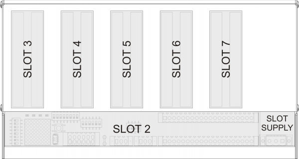
| I33 | Head-1: Local Man/Aut | SLOT 2 | RMC-2M [1]cabinet |
|
| I34 | Head-1: Local Jog | |||
| I35 | Head-2: Local Man/Aut | |||
| I36 | Head-2: Local Jog | |||
| I37 | Head-3: Local Man/Aut | |||
| I38 | Head-3: Local Jog | |||
| I39 | Head-4: Local Man/Aut | |||
| I40 | Head-4: Local Jog | |||
| I41 | Head-5: Local Man/Aut | |||
| I42 | Head-5: Local Jog | |||
| I43 | Head-6: Local Man/Aut | |||
| I44 | Head-6: Local Jog | |||
| I45 | Head-7: Local Man/Aut | |||
| I46 | Head-7: Local Jog | |||
| I47 | Head-8: Local Man/Aut | |||
| I48 | Head-8: Local Jog | |||
| I49 | Head-9: Local Man/Aut | |||
| I50 | Head-9: Local Jog | |||
| I51 | Head-10: Local Man/Aut | |||
| I52 | Head-10: Local Jog | |||
| I53 | Head-11: Local Man/Aut | |||
| I54 | Head-11: Local Jog | |||
| I55 | Head-12: Local Man/Aut | |||
| I56 | Head-12: Local Jog | |||
| I57 | Not used | |||
| I58 | Not used | |||
| I59 | Not used | |||
| I60 | Not used | |||
| I61 | Not used | |||
| I62 | Not used | |||
| I63 | Not used | |||
| I64 | Not used |
| Name | Description | Terminal | Terminal Block | Hardware |
|---|---|---|---|---|
| I65 | Not used | SLOT 3 (I32) | RMC-2M [1]cabinet |
|
| I66 | Not used | |||
| I67 | Not used | |||
| I68 | Not used | |||
| I69 | Not used | |||
| I70 | Not used | |||
| I71 | Not used | |||
| I72 | Not used | |||
| I73 | Not used | |||
| I74 | Not used | |||
| I75 | Not used | |||
| I76 | Not used | |||
| I77 | Not used | |||
| I78 | Not used | |||
| I79 | Not used | |||
| I80 | Not used | |||
| I81 | Not used | |||
| I82 | Not used | |||
| I83 | Not used | |||
| I84 | Not used | |||
| I85 | Not used | |||
| I86 | Not used | |||
| I87 | Not used | |||
| I88 | Not used | |||
| I89 | Not used | |||
| I90 | Not used | |||
| I91 | Not used | |||
| I92 | Not used | |||
| I93 | Not used | |||
| I94 | Not used | |||
| I95 | Not used | |||
| I96 | Not used |
| Name | Description | Terminal | Terminal Block | Hardware |
|---|---|---|---|---|
| I97 | Bar sensor 1 | SLOT4 (I32) | RMC-2M [1]cabinet |
|
| I98 | Bar sensor 2 | |||
| I99 | Bar sensor 3 | |||
| I100 | Bar sensor 4 | |||
| I101 | Bar sensor 5 | |||
| I102 | Bar sensor 6 | |||
| I103 | Bar sensor 7 | |||
| I104 | Bar sensor 8 | |||
| I105 | Bar sensor 9 | |||
| I106 | Bar sensor 10 | |||
| I107 | Bar sensor 11 | |||
| I108 | Bar sensor 12 | |||
| I109 | Bar sensor 13 | |||
| I110 | Bar sensor 14 | |||
| I111 | Bar sensor 15 | |||
| I112 | Bar sensor 16 | |||
| I113 | Bar sensor 17 | |||
| I114 | Bar sensor 18 | |||
| I115 | Bar sensor 19 | |||
| I116 | Bar sensor 20 | |||
| I117 | Bar sensor 21 | |||
| I118 | Bar sensor 22 | |||
| I119 | Bar sensor 23 | |||
| I120 | Bar sensor 24 | |||
| I121 | Bar sensor 25 | |||
| I122 | Bar sensor 26 | |||
| I123 | Bar sensor 27 | |||
| I124 | Bar sensor 28 | |||
| I125 | Bar sensor 29 | |||
| I126 | Bar sensor 30 | |||
| I127 | Bar sensor 31 | |||
| I128 | Bar sensor 32 |
| Name | Description | Terminal | Terminal Block | Hardware |
|---|---|---|---|---|
| I129 | Bar sensor 33 | SLOT5 (I32) | RMC-2M [1]cabinet |
|
| I130 | Bar sensor 34 | |||
| I131 | Bar sensor 35 | |||
| I132 | Bar sensor 36 | |||
| I133 | Bar sensor 37 | |||
| I134 | Bar sensor 38 | |||
| I135 | Bar sensor 39 | |||
| I136 | Bar sensor 40 | |||
| I137 | Bar sensor 41 | |||
| I138 | Bar sensor 42 | |||
| I139 | Bar sensor 43 | |||
| I140 | Bar sensor 44 | |||
| I141 | Bar sensor 45 | |||
| I142 | Bar sensor 46 | |||
| I143 | Bar sensor 47 | |||
| I144 | Bar sensor 48 | |||
| I145 | Bar sensor 49 | |||
| I146 | Bar sensor 50 | |||
| I147 | Bar sensor 51 | |||
| I148 | Bar sensor 52 | |||
| I149 | Bar sensor 53 | |||
| I150 | Bar sensor 54 | |||
| I151 | Bar sensor 55 | |||
| I152 | Bar sensor 56 | |||
| I153 | Bar sensor 57 | |||
| I154 | Bar sensor 58 | |||
| I155 | Bar sensor 59 | |||
| I156 | Bar sensor 60 | |||
| I157 | Bar sensor 61 | |||
| I158 | Bar sensor 62 | |||
| I159 | Bar sensor 63 | |||
| I160 | Bar sensor 64 |
| Name | Description | Terminal | Terminal Block | Hardware |
|---|---|---|---|---|
| I161 | Heads: cutouts | NC | SLOT 2 | RMC-2M [2]beam |
| I162.. | Not used | |||
| ..I192 | Not used |
1.1.2 Digital Outputs (n. 48)
| Name | Description | Terminal | Terminal Block | Hardware |
|---|---|---|---|---|
| O1 | AUTOMATIC ON light | CN7 | J1-P51 | |
| O2 | ALARM light | |||
| O3 | PRE-START light | |||
| O4 | RUN light | |||
| O5 | Beam 1 enable | |||
| O6 | Not used | |||
| O7 | Belt start | |||
| O8 | Belt stop | |||
| O9 | Roller start | CN8 | ||
| O10 | Brush Up/Down | |||
| O11 | Upline machine consensus | |||
| O12 | Lubrification | |||
| O13 | Spray On/Off | |||
| O14 | Not used | |||
| O15 | Not used | |||
| O16 | Not used | |||
| O17 | Not used | CN9 | ||
| O18 | Not used | |||
| O19 | Not used | |||
| O20 | Not used | |||
| O21 | Not used | |||
| O22 | Not used | |||
| O23 | Not used | |||
| O24 | Not used | |||
| O25 | Not used | CN10 | ||
| O26 | Not used | |||
| O27 | Not used | |||
| O28 | Not used | |||
| O29 | Not used | |||
| O30 | Not used | |||
| O31 | Not used | |||
| O32 | Not used |
| Name | Description | Terminal | Terminal Block | Hardware |
|---|---|---|---|---|
| O33 | Head 11: Start | SLOT5 (G12) | RMC-2M beam [2] |
|
| O34 | Head 11: Up | |||
| O35 | Head 11: Down | |||
| O36 | Head 12: Start | |||
| O37 | Head 12: Up | |||
| O38 | Head 12: Down | |||
| O39 | Not used | SLOT6 (G12) | ||
| O40 | Not used | |||
| O41 | Not used | |||
| O42 | Not used | |||
| O43 | Not used | |||
| O44 | Not used | |||
| O45 | Head 1: Start | SLOT7 (P32) | ||
| O46 | Head 1: Up | |||
| O47 | Head 1: Down | |||
| O48 | Head 2: Start | |||
| O49 | Head 2: Up | |||
| O50 | Head 2: Down | |||
| O51 | Head 3: Start | |||
| O52 | Head 3: Up | |||
| O53 | Head 3: Down | |||
| O54 | Head 4: Start | |||
| O55 | Head 4: Up | |||
| O56 | Head 4: Down | |||
| O57 | Head 5: Start | |||
| O58 | Head 5: Up | |||
| O59 | Head 5: Down | |||
| O60 | Head 6: Start | |||
| O61 | Head 6: Up | |||
| O62 | Head 6: Down | |||
| O63 | Head 7: Start | |||
| O64 | Head 7: Up | |||
| O65 | Head 7: Down | |||
| O66 | Head 8: Start | |||
| O67 | Head 8: Up | |||
| O68 | Head 8: Down | |||
| O69 | Head 9: Start | |||
| O70 | Head 9: Up | |||
| O71 | Head 9: Down | |||
| O72 | Head 10: Start | |||
| O73 | Head 10: Up | |||
| O74 | Head 10: Down | |||
| O75 | Not used | |||
| O76 | Not used |
1.1.3 Two-way Encoder Count Inputs (n. 2)
| Name | Description | Terminal | Terminal Block | Hardware |
|---|---|---|---|---|
| PHA1 PHB1 | Beam | CN15 | J1-P51 | |
| PHA2 PHB2 | Not used | CN16 | ||
| PHA3 PHB3 | Belt | CN17 | ||
| PHA4 PHB4 | Not used | CN18 |
1.1.4 Analog Inputs (n. 24)
| Name | Description | Terminal | Terminal block | Hardware |
|---|---|---|---|---|
| AI1 | Not used | CN28 | J1-P51 | |
| AI2 | Not used | |||
| AI3 | Not used | CN29 | ||
| AI4 | Not used |
| Name | Description | Terminal | Terminal Block | Hardware |
|---|---|---|---|---|
| AI5 | Abrasive Wear Head-1 | SLOT 3 (A12) | RMC-2M [2]beam |
|
| AI6 | Abrasive Wear Head-2 | |||
| AI7 | Abrasive Wear Head-3 | |||
| AI8 | Abrasive Wear Head-4 | |||
| AI9 | Abrasive Wear Head-5 | |||
| AI10 | Abrasive Wear Head-6 | |||
| AI11 | Abrasive Wear Head-7 | |||
| AI12 | Abrasive Wear Head-8 | |||
| AI13 | Abrasive Wear Head-9 | SLOT 4 (A12) | ||
| AI14 | Abrasive Wear Head-10 | |||
| AI15 | Abrasive Wear Head-11 | |||
| AI16 | Abrasive Wear Head-12 | |||
| AI17 | Motor Current Head-1 | |||
| AI18 | Motor Current Head-2 | |||
| AI19 | Motor Current Head-3 | |||
| AI20 | Motor Current Head-4 | |||
| AI21 | Motor Current Head-5 | SLOT 5 (G12) | ||
| AI22 | Motor Current Head-6 | |||
| AI23 | Motor Current Head-7 | |||
| AI24 | Motor Current Head-8 | |||
| AI25 | Motor Current Head-9 | SLOT 6 (G12) | ||
| AI26 | Motor Current Head-10 | |||
| AI27 | Motor Current Head-11 | |||
| AI28 | Motor Current Head-12 |
1.1.5 Analog outputs (n. 14)
| Name | Description | Terminal | Terminal Block | Hardware |
|---|---|---|---|---|
| AO1 | Beam speed control ±10Vdc | CN26 | J1-P51 | |
| AO2 | Not used | |||
| AO3 | Belt speed control ±10Vdc | |||
| AO4 | Not used |
| Name | Description | Terminal | Terminal Block | Hardware |
|---|---|---|---|---|
| AO5 | Push Head-1 | SLOT 5 (G12) | RMC-2M [2]beam |
|
| AO6 | Push Head-2 | |||
| AO7 | Push Head-3 | |||
| AO8 | Push Head-4 | |||
| AO9 | Push Head-5 | |||
| AO10 | Push Head-6 | |||
| AO11 | Push Head-7 | SLOT 6 (G12) | ||
| AO12 | Push Head-8 | |||
| AO13 | Push Head-9 | |||
| AO14 | Push Head-10 | |||
| AO15 | Push Head-11 | |||
| AO16 | Push Head-12 |
2. Electrical Connections
Standard Hardware manuals
J1-P51-FC20 link to manual: http://www.qem.eu/doku/doku.php/en/strumenti/qmoveplus/j1p51/mimj1p51fx_full
RMC 2M link to manual: http://www.qem.eu/doku/doku.php/en/strumenti/moduli/rmc2m/mimrmc2m
3. Setup
 |   password 462 |  |
 | Password requested |
 | No password requested |
3.1 General Setup


| Parameter | Unit measure | Default | Range | Description |
|---|---|---|---|---|
| PG01 : FIRST LANGUAGE | - | ENG | - | ENG = ENGLISH ITA = ITALIAN FRA = FRENCH POR = PORTUGUESE SPA = SPANISH DEU = GERMAN TUR = TURKISH CHI = CHINESE EGY = EGYPTIAN POL = POLISH RUS = RUSSIAN |
| PG02 : SECOND LANGUAGE | - | ITA | - | |
| PG03 : DECIMAL POINT | - | 1 | 0 – 2 | Number of decimals shown for distance measures |
| PG04 : LINEAR STEP | mm | 50.0 | 1.0 – 9999.9 | Linear read spacing. Distance between readings on the Scan bar state |
| PG05 : CROSS STEP | mm | 50.0 | 1.0 – 9999.9 | Cross read spacing. Distance between the sensors on the Scan bar |
| PG06 : SLABS FEED FROM | - | LEFT | LEFT – RIGHT | Which side the display is installed |
| PG08 : ABRASIVE ANALOG | - | OFF | OFF – ON | Enable analog IN for abrasive control |
| PG09 : ABRASIVE WARNING | mm | 0.0 | 0.0 – 9999.9 | Abrasive low warning thickness |
| PG10 : ABRASIVE ALARM | mm | 0.0 | 0.0 – 9999.9 | Abrasive low alarm thickness |
| PG12 : CURRENT MANAGEMENT | - | OFF | OFF – READ – CTRL | READ = read only no control CTRL = read and control |
| PG13 : N°WARNING = ALARM | - | 10 | 0 – 99999 | Number of warning events to generate an alarm |
| PG21 : MOTORS OUTPUT | - | CONSTANT | CONSTANT – PULSE | Head operating mode CONSTANT = always active when heads are operating PULSE = active for a set time (PG22). |
| PG22 : PULSE TIME | s | 0.000 | 0 – 99.999 | Heads active time, if operation set to PULSE |
| PG23 : MOT.SEQ.TIME ON | s | 1.000 | 0 – 99.999 | Delay between the startup of one motor and another (startup sequence) |
| PG24 : MOT.SEQ.TIME OFF | s | 0.200 | 0 – 99.999 | Delay between the shutoff of one motor and another (stop sequence) |
| PG25 : MOT.OFF SLAB OUT | s | 0.000 | 0 – 99.999 | Delay before the motor shutoff sequence, when no slabs are on the belt |
| PG30 : PRE-START TIME | s | 3.0 | 0 – 9999.9 | Delay after Start for machine to start working (there is a warning during this time). If less than the motor startup time, the greater is counted. |
| PG31 : LUBRIC. TIME ON | s | 0.0 | 0 – 9999.9 | Lubrication time. |
| PG32 : LUBRIC. TIME OFF | s | 0.0 | 0 – 9999.9 | Lubrication off time. |
| PG34 : BRUSH EARLY | mm | 0.0 | 0 – 9999.9 | Brush down anticipation |
| PG35 : BRUSH DELAY | mm | 0.0 | 0 – 9999.9 | Brush up delay |
| PG36 : REF. SPEED | m/min | 0.0 | 0 – 9999.9 | Speed reference for the brush corrections Proportional correction varies with the speed change Setting = 0 Constant correction at any speed |
| PG38 : SPRAY EARLY | mm | 0.0 | 0 – 9999.9 | Spray on anticipation |
| PG39 : SPRAY DELAY | mm | 0.0 | 0 – 9999.9 | Spray off delay |
| PG40 : REF. SPEED | m/min | 0.0 | 0 – 9999.9 | Speed reference for the spray corrections Proportional correction varies with the speed change Setting = 0 Constant correction at any speed |
3.2 Beam Setup


| Parameter | Unit measure | Default | Range | Description |
|---|---|---|---|---|
| PB01 : MEASURE | mm | 0.1 | 0 – 99999.9 | Distance in unit measures, made by the Beam for the encoder pulses at the parameter pulse. |
| PB02 : PULSE | - | 1 | 0 – 999999 | Beam encoder pulses, multiplied by 4 to get the distance at the parameter measure. The measure to pulse ratio, is the encoder resolution and must be between 1 and 0.000935. |
| PB03 : TOLERANCE | mm | 5.0 | 0 – 99999.9 | Maximum deviation of the count around the positioning, for it to be considered correct |
| PB04 : ENABLE TIME | s | 0.200 | 0.000 – 9.999 | Time before starting the Beam movement |
| PB05 : DISABLE TIME | s | 0.200 | 0.000 – 9.999 | Time after ending the Beam movement |
| PB06 : MAXPOS | mm | 99999.9 | -99999.9 – 99999.9 | Maximum Beam position |
| PB07 : MINPOS | mm | -99999.9 | -99999.9 – 99999.9 | Minimum Beam position |
| PB08 : ACCELERATION TIME | s | 1.00 | 0.00 – 9.99 | Time from 0 to maximum speed |
| PB09 : DECELERATION TIME | s | 1.00 | 0.00 – 9.99 | Time from maximum to 0 speed |
| PB10 : INVERSION TIME | s | 0.50 | 0.00 – 9.99 | Anti-stress protection against rapid direction changes |
| PB11 : DISACTIVAT'N TIME | s | 0 | 0 – 99999 | Maximum delay for the Beam, before the axis enable output is disactivated |
| PB12 : BRAKE OUTPUT | - | OFF | ON – OFF | Enable mode for the axis output ON: Output ON before axis movement and OFF at end, see parameters PB04 and PB05 OFF: Output ON before axis movement and OFF only in emergency |
| PB14 : HOMING POSITION | mm | 0.0 | -99999.9 – 99999.9 | Axis Homing position |
| PB15 : HOMING SPEED | % | 5 | 1 – 100 | Axis speed, when searching for the homing sensor |
| PB16 : HOMING SLOW SPEED | % | 2 | 1 – 100 | Speed for disengaging the homing sensor. |
| PB17 : HOMING DIRECTION | - | FORWARD | FORWARD – BACKWARD | Axis direction for Homing |
| PB18 : STOP POSITION | - | PB06 | PB06 – PB07 | Beam position, when the cycle is stopped PB06 = maximum position, PB07 = minimum position |
| PB19 : CHANGE ABR POSITION | mm | 0.0 | -99999.9 – 99999.9 | Beam position when changing abrasive |
3.2.1 Resolution


Procedure

-
 and check ENCODER increases (Analog out +1 Volt)
 -
 and check ENCODER decreases (Analog out -1 Volt)
 -
A - A' = Maximum MEASURE
-
Note the start position (A)
-
 Zero-set ENCODER
 -
Move the axis from A to A'
-
Note the ENCODER reading and enter it in PULSE
-
Measure the distance from A to A' = space delta
-
Enter the A - A' space delta in MEASURE
Important:
-
PULSE must always be greater than MEASURE (recommended MEASURE x 10 = PULSE)
-
Enter MEASURE in the set unit measure format. e.g. unit measure = 0.1 mm and space delta = 133.5mm, enter 1335 in MEASURE
3.2.2 P.I.D.


The PI + FF calibration procedure:
Space feedback corrects the axis position according to the follow error reading.
Settings in yellow can be modified for the calibration.
Service data is in green and only used for the setup procedure.
| Parameter name | Unit measure | Default | Range | Description |
|---|---|---|---|---|
| VOLTAGE OUT | V | 0.0 | -10.0 – 10.0 | Output voltage, with 0.1V precision, sent directly to the device |
| OFFSET | V | 0.0000 | -99.9999 – 99.9999 | Voltage added to the analog output to compensate any supply voltage irregularities |
| SPEED | mm/min | - | - | The real axis speed |
| MAX SPEED | mm/' | 1000 | 0 – 9999999 | Axis speed at an analog output of 10V |
| POSITION | mm | - | - | The real axis position |
| DELTA | mm | 0.0 | - | Delta space between two positions |
| SET SPEED | mm/' | 0 | - | Axis speed during positioning |
| ACC. TIME | s | 1.00 | - | Acceleration time during positioning |
| DEC. TIME | s | 1.00 | - | Deceleration time during positioning |
| FEEDFORWARD | % | 100.0 | 0.0 – 200.0 | Percentage speed multiplier to generate the feed-forward quota of the analog output |
| PROP. GAIN | - | 0.010 | 0.000 – 9.999 | The follow error multiplier to generate the proportional quota of the analog output |
| T INTEGRAL | s | 0.000 | 0.000 – 9.999 | The integration time coefficient of the follow error. The error integration multiplier to generates the integral quota of the analog output |
| MAX FOLLOW ERR. | mm | 99999.9 | 0.0 – 99999.9 | The maximum drift between the calculated axis position and real axis position |
| FOLLOW ERR. | mm | - | - | The real follow error reading |
First complete the following procedures:
-
RESOLUTION: set the resolution.
-
MAX POSITION: enter a very large positive setting (e.g. 99999.9 mm)
-
MIN POSITION: enter a very large negative setting (e.g. - 99999.9 mm)
IMPORTANT! Essential conditions for the all procedures:
 Ensure that the emergency button shuts off the power to the motors so that the machine can be put in a safety condition.
 All emergency conditions on the machine must be eliminated.
Procedures
| OFFSET | |
|---|---|
| 1 |  to start calibration to start calibration |
| 2 | Set OUT VOLTAGE = 0 |
| 3 | Regulate the OFFSET (directly by |
| 4 |  to quit calibration to quit calibration |
| Rotation direction and count | |
|---|---|
| An output voltage > 0 increases POSITION | |
| 1 | to start calibration |
| 2 | Enter VOUT = 1.0 |
| 3 | Check that POSITION increases |
| 4 | to exit calibration and check that VOUT goes to 0 immediately |
| 5 | If the motor does not rotate in the correct direction, change the drive setup or cabling |
| Maximum speed | |
|---|---|
| Setting the maximum axis speed (10V output) | |
| 1 | to enter calibration |
| 2 | Enter VOUT > 1.0 (as close to 10V as possible) |
| 3 | Note the SPEED reading |
| 4 | Calculate the MAX SPEED: MAX SPEED = (10 x SPEED) / VOUT |
| 5 | to exit calibration and check that VOUT goes to 0 immediately |
| 6 | Enter the above calculation result in MAX SPEED |
| Space Feedback | ||||||||||||||
|---|---|---|---|---|---|---|---|---|---|---|---|---|---|---|
| Important: first complete all previous procedures | ||||||||||||||
| 1 | Enter FEEDFORWARD = 100.0 | |||||||||||||
| 2 | Enter PROP. GAIN = minimum setting (0.001) | |||||||||||||
| 3 | If FOLLOW ERR is not 0, now this reading will reduce with an axis movement | |||||||||||||
| 4 | Enter DELTA = any distance and SET SPEED = a speed (nearly MAX SPEED) | |||||||||||||
| 5 |  to start the axis movements to start the axis movements |
|||||||||||||
| 6 | The axis moves forward by the distance in DELTA at the speed in SET SPEED | |||||||||||||
| 7 | The axis then returns to the start position and repeats the movement | |||||||||||||
| 8 | During the movements note the FOLLOW ERR reading and vary FEEDFORWARD and PROP. GAIN to keep it as low as possible. Setting rules
|
|||||||||||||
| 9 | When the axis movement overshoots MAX FOLLOW ERROR you will see the warning symbol |
|||||||||||||
| 10 |  to quit the procedure to quit the procedure |
|||||||||||||
3.3 Heads Setup


| Parameter | Unit measure | Default | Range | Description |
|---|---|---|---|---|
| PH01 / PH12 : DIAMETER | mm | 0.0 | 0 – 99999.9 | Head diameter |
| PH25 / PH48 : VERTICAL SPACING | mm | 0.0 | 0 – 99999.9 | Distance from the head and central point of the bridge |
| PH49 / PH72 : TIME TO STANDY UP | s | 0.500 | 0 – 999.999 | The up movement time for the standby up |
| PH73 : BRAKE MODE | - | Out Off Brake activated | Out Off – Out On Brake activated | Brake output state when activated |
| PH74 : UP DELAY | s | 0.000 | 0 – 999.999 | Delay time for the total up of the heads |
| PH75 : READ DELAY | s | 1.000 | 0 – 999.999 | Delay from head down and reading |
| PH76 : READ AGAIN | s | 5.000 | 0 – 999.999 | Repeat read time with head down |
3.4 Head Spacing Setup


Set the distance from the Scan bar to the Center of each Head, Spray and Brush
3.5 Abrasives Setup


| Parameter | Unit measure | Default | Range | Description |
|---|---|---|---|---|
| READING | bit | - | - | Analog input reading |
| REAL DISTANCE | mm | - | - | Conversion of bit in mm |
| HEAD UP | ||||
| SETTING | bit | 0 | 0 – 4095 | Enter READING as the setting |
| - | - | - | Auto setting of READING | |
| DISTANCE | mm | 0 | 0 – 9999.9 | Set measured distance between head and belt |
| HEAD DOWN | ||||
| SETTING | bit | 0 | 0 – 4095 | Enter READING as the setting |
| - | - | - | Auto setting of READING | |
| DISTANCE | mm | 0 | 0 – 9999.9 | Set measured distance of abrasive + slab |
| Auto OFF | | Auto ON | |
| Head UP | | Head DOWN | |
| Motor OFF | | Motor ON |
3.6 Currents Setup


| Parameter | Unit measure | Default | Range | Description |
|---|---|---|---|---|
| READING | bit / mA | - | - | Analog input reading |
| REAL CURRENT | A | - | - | Conversion of bit in A |
| MIN CURRENT DRAW | ||||
| SETTING | bit | 800 | 0 – 4095 | Enter READING as the setting |
| - | - | - | Auto setting of READING | |
| CURRENT | A | 0.0 | 0 – 9999.9 | Set minimum current |
| MAX CURRENT DRAW | ||||
| SETTING | bit | 4095 | 0 – 4095 | Set maximum bit |
| CURRENT | A | 20.0 | 0 – 9999.9 | Set maximum datasheet current |
| Auto OFF | | Auto ON | |
| Head UP | | Head DOWN | |
| Motor OFF | | Motor ON |
3.7 Valves Setup


| Parameter | Unit measure | Default | Range | Description |
|---|---|---|---|---|
| VOLTAGE OUTPUT | V | 0.0 | 0 – 10.0 | Enter a voltage output for testing |
| CURRENT READ | A | - | - | Result of voltage output setting |
| Auto OFF | | Auto ON | |
| Head UP | | Head DOWN | |
| Motor OFF | | Motor ON |
3.8 Belt Setup


| Parameter name | Unit measure | Default | Range | Description |
|---|---|---|---|---|
| PB51 : MEASURE | mm | 0.1 | 0 – 99999.9 | The space, in the unit measure, travelled by the Beam to obtain the encoder pulses, set at the parameter pulse. |
| PB52 : PULSE | - | 1 | 0 – 999999 | The pulses supplied by the Beam encoder, multiplied by 4 to obtain the space, set at the parameter measure. The measure to pulse ratio, is the encoder resolution and must be between 1 and 0.000935. |
| PB54 : BELT SPEED BY | - | DISPLAY | DISPLAY | Only display mode |
| PB55 : 10V SPEED | m/min | 5.0 | 0 – 999.9 | Speed at 10V analog output |
| PB56 : MAX SET SPEED | m/min | 0.0 | 0 – 999.9 | Max speed limit |
| PB57 : MIN SET SPEED | m/min | 0.0 | 0 – 999.9 | Min speed limit |
| PB58 : BELT OUTPUT | - | CONSTANT | CONSTANT – PULSE | Belt operating mode CONSTANT = always active when belt is operating PULSE = active for a set time (PB59) |
| PB59 : PULSE TIME | s | 0.0 | 0 – 9.999 | Belt active time, if operation set to PULSE |
| PB60 : BELT DELAY | s | 0.0 | 0 – 9.999 | Belt start delay after all heads ON |
3.8.1 Calibration
| Parameter name | Unit measure | Default | Range | Description |
|---|---|---|---|---|
| VOLTAGE OUT | V | 0.0 | -10.0 – 10.0 | Output voltage, with 0.1V precision, sent directly to the device |
| OFFSET | V | 0.0000 | -99.9999 – 99.9999 | Voltage added to the analog output to compensate any supply voltage irregularities |
| SPEED | mm/min | - | - | The real axis speed |
| MAX SPEED | mm/' | 1000 | 0 – 9999999 | Axis speed at an analog output of 10V |
| POSITION | mm | - | - | The real axis position |
| OFFSET | |
|---|---|
| 1 | to start calibration |
| 2 | Set OUT VOLTAGE = 0 |
| 3 | Regulate the OFFSET (directly by |
| 4 | to quit calibration |
| Rotation direction and count | |
|---|---|
| An output voltage > 0 increases POSITION | |
| 1 | to start calibration |
| 2 | Enter VOUT = 1.0 |
| 3 | Check that POSITION increases |
| 4 | to exit calibration and check that VOUT goes to 0 immediately |
| 5 | If the motor does not rotate in the correct direction, change the drive setup or cabling |
| Maximum speed | |
|---|---|
| Setting the maximum axis speed (10V output) | |
| 1 | to enter calibration |
| 2 | Enter VOUT > 1.0 (as close to 10V as possible) |
| 3 | Note the SPEED reading |
| 4 | Calculate the MAX SPEED: MAX SPEED = (10 x SPEED) / VOUT |
| 5 | to exit calibration and check that VOUT goes to 0 immediately |
| 6 | Enter the above calculation result in MAX SPEED |
3.9. Sensors Setup


| Sensor enabled | Sensor disabled |
N.B. Two adjacent sensors cannot be disabled. Only disable alternate sensors.
| Parameter | Unità di misura | Default | Range | Description |
|---|---|---|---|---|
| PS01 : NUMBER OF SENSORS | - | 32 | 8 – 64 | Number of sensors on the Sensor Bar |
| PS02 : SENSOR TYPE | - | N.O. | N.O. – N.C. | Scan bar input logic N.O. = Normally Open N.C. = Normally Closed |
3.10. Touchscreen Calibration

