目录
P1K31FR30-001 - 3 axis bridge saw: Installation Manual
| Document | P1K31FR30-001 | ||
|---|---|---|---|
| Description | User manual | ||
| Drawn up | Riccardo Furlato | ||
| Approved | Draft | ||
| Link: | http://www.qem.eu/doku/doku.php/en/strumenti/qmoveplus/j1k31/mdu_p1k31fr30-001/funzionamento | ||
| Languages | English | ||
| Release | Description | Notes | Date |
| 01 | New Manual | 26/05/14 | |
目录
All rights reserved on this manual. No part of this document can be copied or reproduced in any form without prior written authorisation. QEM does not insure or guarantee its contents and explicitly declines all liability related to the guarantee of its suitability for any purpose. The information in this document can be changed without notice. QEM shall not be held liable for any error or omission in this document. QEM® is a registered trademark.Microsoft® and MS-DOS® are registered trademarks and Windows® is a trademark of Microsoft Corporation.
0.1 Tasti
| Press to confirm | |
| Select multile parameters | |
 | Previous screen |
 | Next screen |
 | General Setup (protected by password) |
| Apri da MMC | |
| Salva |
Campi numerici gialli …possono essere impostati 
0.2 Function leds
| Led | Icona | Funzione | Led | Icona | Funzione |
|---|---|---|---|---|---|
| F4 | | Barriere | F5 | non usato | non usato. |
| F6 | | Laser Y ON/OFF | F7 | | Laser X ON/OFF |
| F8 | | EV acqua ON/OFF | F9 | | Allarme = ON |
| F10 | | Esci | F11 | | Semiautomatico = ON |
| F12 | | Alza banco | F13 | | Abbassa banco |
| F14 | | Rotazione antioraria banco | F15 | | Rotazione oraria banco |
| F16 | | Disco ON/OFF | F17 | | Fresa ON/OFF |
0.3 Symbols
| Symbol | Description |
|---|---|
| | Manual |
| | Emergency |
| | Automatic |
| | Function mode |
| | Not initialized |
| | Locked/Unlocked setup |
0.4 Up-bar
| Symbol | Description |
|---|---|
 | Barra alta (sfondo grigio)
|
1. STARTUP PAGE
![]()
La pagina resta attiva con il messaggio “WAITING FOR POWER SYSTEM” finché non viene tolta l'emergenza.
Per proseguire premere 
2. HOMING SCREEN
  | |
||
 |  | ||
2.1 Pagine installatore - Accesso ai parametri di default
| | |
|||
 |  |
|||
 PASSWORD:462  |  |
|||
| G DEF - X DEF Y DEF - Z DEF W DEF - H DEF |  |
|||
2.2 Pagine installatore - Accesso ai parametri di default
| | |
|||
| | |
|||
| PASSWORD:462 | |
|||
| G DEF - X DEF Y DEF - Z DEF W DEF - H DEF | |
|||
2.3 Pagine installatore - Accesso alla diagnostica
| | |
||||
| | |
||||
| PASSWORD:462 | |
||||
 | I/O |  |
|||
| INPUTS  |  |
||||
| OUTPUTS |  |
||||
| COUNTERS |  |
||||
| ANALOG OUTS |  |
||||
2.4 Pagine installatore - Taratura assi
| | |
||||
| | |
||||
| PASSWORD:462 | |
||||
| X CAL - Y CAL Z CAL - W CAL H CAL |  |
||||
| RESOLUTION |  |
||||
| P.I.D. |  |
||||
| LINEARIZATION |  |
||||
3. SETUP
Toccare il valore del parametro e modificare con il tastierino numerico.
Per confermare premere il tasto 
3.1 Caricamento dei parametri di default
| G DEF - X DEF Y DEF - Z DEF W DEF - H DEF | |
|
| YES | Per caricare i dati di default | |
| NO | Per annullare | |
3.2 General Parameters
| GEN  |  |
 previous page previous page next page next page save data if changed save data if changed |
-
PG-XX = Parameters Generic, XX = number
-
U.M. = Unit Measure
-
Def. = Default
| Parameter | U.M. | Def. | Range | Description | |
|---|---|---|---|---|---|
| PG-01 | X/Y/Z 小数点 | X/Y/Z DECIMAL POINT | - | 1 | 0 ~ 2 |
s
Inches will show “DECIMAL POINT + 1 |
| PG-02 | W 小数点 | W DECIMAL POINT | - | 2 | 0 ~ 2 | Number of decimal points for W axis position |
| PG-03 | H 小数点 | H DECIMAL POINT | - | 2 | 0 ~ 2 | Number of decimal points for H axis position |
| PG-04 | 最大刀碟转速 | MAXIMUM DISK RPM | rpm | 2480 | 0 ~ 3000 | Maximum limit of disk rpm. |
| PG-05 | 标线器时间 | LASER TIME | s | 30 | 0 ~ 9999 | If > zero the laser is automatic when Y axis moving. When axis stops after this time, laser powers off automatically. If time is zero the laser can only be operated by F7 button |
| PG-06 | 水控制时间 | WATER CONTROL TIME | s | 5 | 0 ~ 9999 | Time waited before a water fault gives an alarm |
| PG-07 | 关闭水控制 | DISABLE WATER CONTROL | - | 0 | 0 ~ 1 |
1= water control disabled |
| PG-08 | HMI 蜂鸣器 | HMI BEEPER | - | 0 | 0 ~ 1 |
1= beeper disabled |
| PG-09 | 蜂鸣器报警时间 | ALARM BEEPER TIME | s | 10 | 0 ~ 999 | Time of Alarm beeper when in alarm state |
| PG-10 | 测量 | UNIT MEASURE | - | 0 | 0 ~ 1 |
1= inch
In Setup all parameters are in mm |
| PG-11 | 语言 | LANGUAGE | - | 1 | 01/02/14 |
2= ITALIAN |
| PG-12 | 归位模式 | HOMING MODE | - | 1 | 0 ~ 3 |
1= Homing not necessary, all functions are unlocked
2= Homing necessary for automatic cycle, only manual is unlocked
3= Homing necessary to unlock all functions . Homing starts automatically without pressing a button |
| PG-13 | 未使用 | Not Used | - | 0 | Not used | |
| PG-14 | 最少模拟输入 | MINIMUM ANALOG INPUT | bit | 5 | 0 ~ 1000 | If less all analog inputs are forced to zero. |
| PG-15 | 插值速度覆盖 | INTERPOLATION SPEED OVERRIDE | - | 0 | 0 ~ 1 |
1= override applied to set speed |
| PG-16 | 换向类型 | DIRECTION CHANGE TYPE | - | 0 | 0 - 1 |
1= not implemented |
| PG-17 | 换向调整 | DIRECTION CHANGE ADJUSTMENT | mm | 0.5 | 0 - 999.9 | Direction change adjustment with curve radius on corner (x) |
| PG-18 | 快速 | FAST SPEED | mm/min | 1000 | 0 - 9999 | Speed for straight cut and default value for other blocks. |
| PG-19 | 最大电流 = 10V | MAXIMUM CURRENT = 10Volt | A | 100.0 | 0 - 100.0 | Maximum current of analogic input for spindle current |
| PG-20 | 主轴速度就需时间 | SPINDLESPEED OK TIME | s | 0 | 0 - 99.999 |
>0= machine waits only this time” |
| PG-21 | 最大磨转速 | MAXIMUM MILL RPM | rpm | 3000 | 0 - 3000 | Maximum limit of mill rpm. |
| PG-22 | 归位序列 | HOMING SEQUENCE | - | 0 | 0 - 1 |
1= after Z axis homing, the others are done together |
(x) 参数小数点 依赖 PG-01 参数 parameter decimal point depends on PG-01
3.3 X, Y, Z 轴 设置 X, Y, Z axis setup
| X SETUP  Y SETUP  Z SETUP  | |
| previous page next page save data if changed |
-
PX-XX = Parameters, X = axe, XX = number
-
P.ter = Parameters
-
U.M. = Unit Measure
-
Def. = Default
| P.ter | U.M. | Def. | Range | Description | ||
|---|---|---|---|---|---|---|
| PX-01 | 测量 | MEASURE | mm | 0.1 | 0 - 99999.9 | Distance of the axis movement to obtain the pulses set in parameter PULSE (x) |
| PX-02 | 脉冲 | PULSE | - | 1 | 0 - 999999 |
Measure/Pulse is the axis resolution. It must be between 1 and 0.000935 |
| PX-03 | 公差 | TOLERANCE | mm | 0.5 | 0 - 99.99 | Distance around target position that is considered correct.(xx) |
| PX-04 | 启用时间 | ENABLE TIME | s | 0.200 | 0 - 9.999 | Time before axis is ok to start moving |
| PX-05 | 关闭时间 | DISABLE TIME | s | 0.200 | 0 - 9.999 | Time after axis is ok to stop |
| PX-06 | 启用轴输出 | ENABLE AXIS OUTPUT | - | 1 | 0 - 1 |
0= output ON before axis movement and OFF after axis stop, after time set in PX-04 and PX-05
1= always on (except in alarm state) |
| PX-07 | 点动功能 | JOG FUNCTION | - | 1 | 0 - 1 | Jog function type 0= jog is open loop 1= jog is closed loop |
| PX-08 | 最大位置 | MAXIMUM POSITION | mm | 34463.09.00 | -99999.9 - 99999.9 | Maximum axis position. Software limit switch(x) |
| PX-09 | 最少位置 | MINIMUM POSITION | mm | -34463.09.00 | -99999.9 - 99999.9 | Minimum axis position. Software limit switch(x) |
| PX-10 | 归位补偿 | HOMING OFFSET | mm | 0 | -99999.9 - 99999.9 | Distance between zero and sensor. |
| PX-11 | 归位类型 | HOMING TYPE | - | 0 | 0 - 3 | 0= Axis searches the homing sensor, reverses movement and set PX-10 position 1= Axis searches the homing sensor, inverts movement and set PX-10 position on encoder zero signal 2= Axis homing without movement. Set PX-10 position on homing sensor signal 3= homing disabled |
| PX-12 | 归位方向 | HOMING DIRECTION | - | 0 | 0 - 1 | 0= forward 1= backward |
| PX-13 | 快速归位 | HOMING FAST SPEED | mm/min | 10 | 0 - 9999999 | Homing sensor searching speed |
| PX-14 | 慢速归位 | HOMING SLOW SPEED | mm/min | 10 | 0 - 9999999 | Axis speed after reverse movement in homing |
| PX-15 | 归位缺省值 | HOMING DEFAULT | - | 1 | 0 - 1 | 0= Axis not included in automatic homing 1= Axis included in automatic homing |
| PX-16 | 自动加速时间 | AUTOMATIC ACCELERATION TIME | s | 1.00 | 0 - 9.99 | Time from 0 to maximum speed |
| PX-17 | 自动减速时间 | AUTOMATIC DECELERATION TIME | s | 1.00 | 0 - 9.99 | Time from maximum speed to 0 |
| PX-18 | 手动加速时间 | MANUAL ACCELERATION TIME | s | 1.00 | 0 - 9.99 | Time from 0 to maximum speed |
| PX-19 | 手动减速时间 | MANUAL DECELERATION TIME | s | 1.00 | 0 - 9.99 | Time from maximum speed to 0 |
| PX-20 | 公差延迟时间 | TOLERANCE CONTROL DELAY | s | 0.50 | 0 - 99.99 | Time between axis stop and tolerance control |
| PX-21 | 自动向前速度 | AUTOMATIC SPEED FORWARD | mm/min | 10 | 0 - 9999999 | Axis forward speed in automatic cycle. |
| PX-22 | 自动向后速度 | AUTOMATICSPEED BACKWARD | mm/min | 10 | 0 - 9999999 | Axis backward speed in automatic cycle. |
| PX-23 | 手动快度 | MANUAL FAST SPEED | mm/min | 10 | 0 - 9999999 | Axis fast speed during manual jog movement. |
| PX-24 | 手动慢速 | MANUAL SLOW SPEED | mm/min | 10 | 0 - 9999999 | Axis slow speed during manual jog movement. |
| PX-25 | 最少运动 | MINIMUM MOVEMENT | mm | 00.01.00 | 0 - 999.9 | Encoder fault control: minimum movement for the axis.(x) |
| PX-26 | 最少电压 | MINIMUM VOLTAGE | V | 01.00.00 | 0 - 10.0 | Encoder fault control : minimum voltage to start encoder control. |
| PX-27 | 工作周期终点停放位置 | END WORK CYCLE PARKING | - | 0 | 0 - 1 |
1= enabled |
| PX-28 | 最大速度 | MAXIMUM SPEED | mm/min | 100 | 0 - 9999999 | Axis maximum speed with 10Vdc output |
| PX-29 | 正反馈 | FEEDFORWARD | % | 100.00.00 | 0 - 200.0 | Feedforward register for PID regulation. |
| PX-30 | 比例增益 | PROPORTIONAL GAIN | - | 0 | 0 - 9.999 | Proportional gain register for PID regulation. |
| PX-31 | 整体的时间 | INTEGRAL TIME | s | 0 | 0 - 9.999 | Integral register for PID regulation. |
| PX-32 | 导数时间 | DERIVATIVE TIME | s | 0 | 0 - 9.999 | Derivative register for PID regulation. |
| PX-33 | 最大追踪错误 | MAXIMUM FOLLOWING ERROR | mm | 10000.39.00 | 0 - 9999.99 | Maximum error between theoretic and real axis position(xx) |
| PX-34 | 驱动器补偿 | DRIVE OFFSET | V | 0 | -99.9999 - 99.9999 | Analogic output offset for drive compensation. |
| PX-35 | 最大插值速度 | MAXIMUM INTERPOLATION SPEED | % | 80.00.00 | 0 - 100.0 | Maximum interpolation speed. Percentage of maximum speed in PX-28. |
| PX-36 | 归位器检测开关状态 | HOMING SENSOR LOGIC | - | 0 | 0 - 1 | 0= Sensor NO (normally open) 1= Sensor NC (normally close).“ |
| PX-37 | 靠近位置 | APPROACH POSITION | mm | 10.00.00 | 0 - 999.9 | If more than 0 enables pulse positioning and where it begins before the target (x) |
| PX-38 | 脉冲幅度 | PULSE AMPLITUDE | V | 00.01.00 | 0 - 10.0 | Pulse amplitude in volt. |
| PX-39 | 脉冲时间 | PULSE TIME | s | 00.20.00 | 0 - 99.99 | Time of a single pulse step |
| PX-40 | 脉冲延迟 | PULSE DELAY | s | 00.20.00 | 0 - 99.99 | Time between two steps. |
| PX-41 | 脉冲超时 | PULSE TIMEOUT | s | 0 | 0 - 99 | Pulse positioning maximum time. |
3.3.1 参数 只为 X 轴 Parameters only for X axis
| P.ter | U.M. | Def. | Range | Description | ||
|---|---|---|---|---|---|---|
| PX-42 | 台中心 | TABLE CENTER POSITION | mm | 1000.0 | -99999.9 - 99999.9 | Axis position of the rotary table center (x) |
| PX-43 | 磨-刀碟补偿 | MILL-DISK OFFSET | mm | 0.0 | -99999.9 - 99999.9 | Distance between disk center and mill center. |
| PX-44 | RAMP TYPE | - | 0 | 0 - 1 | 0= Linear ramps 1= Epicyclic ramps |
|
3.3.2 参数 只为 Y 轴 Parameters only for Y axis
| P.ter | U.M. | Def. | Range | Description | ||
|---|---|---|---|---|---|---|
| PY-42 | 台中心 | TABLE CENTER POSITION | mm | 1000.0 | -99999.9 - 99999.9 | Axis position of the rotary table center (x) |
| PY-43 | 公差报警关闭 | TOLERANCE ALARM DISABLE | - | 0 | 0 - 1 | 0= alarm enabled 1= alarm disabled |
| PY-44 | 磨-刀碟补偿 | MILL-DISK OFFSET | mm | 100.0 | -99999.9 - 99999.9 | Distance between disk center and mill center. |
| PY-45 | RAMP TYPE | - | 0 | 0 - 1 | 0= Linear ramps 1= Epicyclic ramps |
|
3.3.3 参数 只为 Z 轴 Parameters only for Z axis
| P.ter | U.M. | Def. | Range | Description | ||
|---|---|---|---|---|---|---|
| PZ-42 | 公差报警关闭 | TOLERANCE ALARM DISABLE | - | 0 | 0 - 1 | “0: alarm enabled 1: alarm disabled” |
| PZ-43 | RAMP TYPE | - | 0 | 0 - 1 | 0= Linear ramps 1= Epicyclic ramps |
|
(x) 参数 小数点 依赖 PG-01 参数 parameter decimal point depend on PG-01 value. (xx) 参数 小数点 依赖 PG-01 参数 加一 parameter decimal point depend on PG-01 value plus one.
3.4 W axis setup
| W SETUP  | |
| previous page next page save data if changed |
-
PX-XX = Parameters, X = axe, XX = number
-
P.ter = Parameters
-
U.M. = Unit Measure
-
Def. = Default
| Parameter | U.M. | Def. | Range | Description | ||
|---|---|---|---|---|---|---|
| PW-01 | 轴启用 | AXIS ENABLE | - | 0 | 0 - 1 | 0= axis disabled 1= axis enabled |
| PW-02 | 测量 | MEASURE | ° | 0.01 | 0 - 9999.99 | Distance of the axis movement to obtain the pulses set in parameter PULSE |
| PW-03 | 脉冲 | PULSE | - | 1 | 0 - 999999 | Encoder pulses corresponding to the distance in MEASURE. Measure/Pulse is the axis resolution. It must be between 1 and 0.000935 |
| PW-04 | 公差 | TOLERANCE | ° | 0.050 | 0 - 99.999 | Distance around target position that is considered correct |
| PW-05 | 启用时间 | ENABLE TIME | s | 0.200 | 0 - 9.999 | Time before axis is ok to start moving |
| PW-06 | 关闭时间 | DISABLE TIME | s | 0.200 | 0 - 9.999 | Time after axis is ok to stop |
| PW-07 | 慢速距离 | DISTANCE IN SLOW | ° | 5.00 | 0 - 99.99 | Distance when axis speed slows down before final target |
| PW-08 | 向前惯性 | FORWARD INERTIA | ° | 0 | 0 - 99.999 | Inertia distance at the end of forward movements. |
| PW-09 | 向后惯性 | BACKWARD INERTIA | ° | 0 | 0 - 99.999 | Inertia distance at the end of backward movements |
| PW-10 | 惯性模式 | INERTIA MODE | - | 0 | 0 - 2 | At the end of positioning 0= inertia not calculated 1= calculated if out of tolerance 2= always calculated |
| PW-11 | 公差延迟时间 | TOLERANCE CONTROL DELAY | s | 1.000 | 0 - 99.99 | Time between axis stop and tolerance control |
| PW-12 | 反弹模式 | BACKLASH MODE | - | 0 | 0 - 4 | 0= no backlash 1= forward backlash 2= backward backlash 3= forward backlash without speed slow down 4= backward backlash without speed slow down |
| PW-13 | 开外位置 | OVER POSITION | ° | 0 | 0 - 999.99 | Over position for backlash |
| PW-14 | 自动快度 | AUTOMATIC FAST SPEED | % | 10.0 | 0 - 100.0 | Axis fast speed during automatic cycle |
| PW-15 | 自动慢速 | AUTOMATIC SLOW SPEED | % | 5.0 | 0 - 100.0 | Axis slow speed during automatic cycle |
| PW-16 | 手动快度 | MANUAL FAST SPEED | % | 10.0 | 0 - 100.0 | Axis fast speed during manual jog movement |
| PW-17 | 手动慢速 | MANUAL SLOW SPEED | % | 5.0 | 0 - 100.0 | Axis slow speed during manual jog movement |
| PW-18 | 归位快度 | HOMING FAST SPEED | % | 10.0 | 0 - 100.0 | Axis speed at the start of homing |
| PW-19 | 归位慢速 | HOMING SLOW SPEED | % | 1.0 | 0 - 100.0 | Axis speed after movement inversion in homing |
| PW-20 | 归位缺省值 | HOMING DEFAULT | - | 1 | 0 - 1 | 0= Axis not included in automatic homing 1= Axis included in automatic homing |
| PW-21 | 归位补偿 | HOMING OFFSET | ° | 0 | -9999.99 - 9999.99 | Set position at the end of homing procedure |
| PW-22 | 归位类型 | HOMING TYPE | - | 0 | 0 - 3 | 0= Axis searches the homing sensor, inverts movement and sets PW-22 position 1= Axis searches the homing sensor, inverts movement and sets PW-22 position on encoder zero signal 2= Axis homing without movement. Set PW-22 position on homing sensor signal. 3= homing disabled. |
| PW-23 | 归位方向 | HOMING DIRECTION | - | 1 | 0 - 1 | 0= forward 1=backward |
| PW-24 | 最大位置 | MAXIMUM POSITION | ° | 9999.9 | -9999.99 - 9999.99 | Maximum position for the axis. Software limit switch |
| PW-25 | 最少位置 | MINIMUM POSITION | ° | -9999.9 | -9999.99 - 9999.99 | Minimum position for the axis. Software limit switch |
| PW-26 | 最少运动 | MINIMUM MOVEMENT | ° | 0.10 | 0 - 99.99 | Encoder fault control: minimum axis movement |
| PW-27 | 最少时间 | MINIMUM TIME | s | 2000 | 0 - 99.99 | Encoder fault control: sample time to check minimum movement |
| PW-28 | 刹车逻辑 | BRAKE LOGIC | - | 1 | 0 - 1 | 0= Brake output N.O. 1= Brake output N.C. |
| PW-29 | 刹车时间 | BRAKE TIME | s | 1.000 | 0 - 9.999 | Enable time before axis starts moving and after axis stop |
| PW-30 | 加速 | ACCELERATION | V/s | 20.00 | 0 - 99.99 | Acceleration setting |
| PW-31 | 减速 | DECELERATION | V/s | 20.00 | 0 - 99.99 | Deceleration setting |
| PW-32 | 脉冲启用 | PULSE ENABLE | - | 0 | 0 - 1 | 0= Pulse positioning disabled 1= Pulse positioning enabled |
| PW-33 | 靠近位置 | APPROACH POSITION | ° | 0-30 | 0 - 999.99 | Position before target where pulse positioning begins |
| PW-34 | 脉冲时间 | PULSE TIME | s | 0.100 | 0 - 9.999 | Time of a single pulse step |
| PW-35 | 脉冲延迟 | PULSE DELAY | s | 0.100 | 0 - 9.999 | Time between two steps |
| PW-36 | 编号脉冲 | NUMBER OF PULSES | - | 40 | 0 - 9999 | Maximum number of pulse steps |
| PW-37 | 脉冲振幅 | PULSE AMPLITUDE | V | 0.1 | 0 - 10.0 | Pulse amplitude in volt |
| PW-38 | 锁启用 | ENABLE LOCKS | - | 0 | 0 - 1 | 0= Locks disabled 1= Locks enabled |
| PW-39 | 锁延迟 | LOCK DELAY | s | 0.200 | 0 - 9.999 | Time between spine insertion and brake output |
| PW-40 | 锁位置1 | LOCK 1 POSITION | ° | 0 | -9999.99 - 9999.99 | Position for lock 1 |
| PW-41 | 锁位置2 | LOCK 2 POSITION | ° | 90.00 | -9999.99 - 9999.99 | Position for lock 2 |
| PW-42 | 启用线性化 | ENABLE LINEARIZATION | - | 0 | 0 - 1 | 0= position linearization disabled 1= position linearization enabled |
| PW-43 | 不线性化位置2 | UNLINEARIZED POSITION 2 | ° | 45.0 | -9999.99 - 9999.99 | Axis unlinearized position in sector 2 |
| PW-44 | 线性化位置2 | LINEARIZED POSITION 2 | ° | 45.0 | -9999.99 - 9999.99 | Axis linearized position in sector 2 |
| PW-45 | 不线性化位置3 | UNLINEARIZED POSITION 3 | ° | 90.0 | -9999.99 - 9999.99 | Axis unlinearized position in sector 3 |
| PW-46 | 线性化位置3 | LINEARIZED POSITION 3 | ° | 90.0 | -9999.99 - 9999.99 | Axis linearized position in sector 3 |
| PW-47 | 不线性化位置4 | UNLINEARIZED POSITION 4 | ° | 135.0 | -9999.99 - 9999.99 | Axis unlinearized position in sector 4 |
| PW-48 | 线性化位置4 | LINEARIZED POSITION 4 | ° | 135.0 | -9999.99 - 9999.99 | Axis linearized position in sector 4 |
| PW-49 | 不线性化位置5 | UNLINEARIZED POSITION 5 | ° | 180.0 | -9999.99 - 9999.99 | Axis unlinearized position in sector 5 |
| PW-50 | 线性化位置5 | LINEARIZED POSITION 5 | ° | 180.00 | -9999.99 - 9999.99 | Axis linearized position in sector 5 |
| PW-51 | 不线性化位置6 | UNLINEARIZED POSITION 6 | ° | 225.0 | -9999.99 - 9999.99 | Axis unlinearized position in sector 6 |
| PW-52 | 线性化位置6 | LINEARIZED POSITION 6 | ° | 225.0 | -9999.99 - 9999.99 | Axis linearized position in sector 6 |
| PW-53 | 不线性化位置7 | UNLINEARIZED POSITION 7 | ° | 270.0 | -9999.99 - 9999.99 | Axis unlinearized position in sector 7 |
| PW-54 | 线性化位置7 | LINEARIZED POSITION 7 | ° | 270.0 | -9999.99 - 9999.99 | Axis linearized position in sector 7 |
| PW-55 | 不线性化位置8 | UNLINEARIZED POSITION 8 | ° | 315.0 | -9999.99 - 9999.99 | Axis unlinearized position in sector 8 |
| PW-56 | 线性化位置8 | LINEARIZED POSITION 8 | ° | 315.0 | -9999.99 - 9999.99 | Axis linearized position in sector 8 |
3.5 H 轴 设置 H axis setup
| H SETUP  | |
| previous page next page save data if changed |
-
PX-XX = Parameters, X = axe, XX = number
-
P.ter = Parameters
-
U.M. = Unit Measure
-
Def. = Default
| Parameter | U.M. | Def. | Range | Description | ||
|---|---|---|---|---|---|---|
| PH-01 | 斜类型 | TILT TYPE | - | 1 | 0 - 1 | 0: axis tilt with Z axis 1: axis tilt with full head |
| PH-02 | 马达 | MOTOR | - | 0 | 0 - 1 | 0: axis without motor 1: axis with motor |
| PH-03 | 编码器 | NOT USED | - | - | - | |
| PH-03 | 编码器 | ENCODER | - | 1 | 0 - 1 | 0: axis without encoder 1: axis with encoder |
| PH-03 | 编码器 | ENCODER | - | 1 | 0 - 1 | 0: axis without encoder 1: axis with encoder |
| PH-04 | 测量 | MEASURE | ° | 0.01 | 0 - 9999.99 | Distance of the axis movement to obtain the pulses set in parameter PULSE |
| PH-05 | 脉冲 | PULSE | - | 1 | 0 - 999999 | Pulses of the encoder corresponding to the distance set in parameter MEASURE. Measure/Pulse is axis resolution. It has to be between 1 and 0.000935 |
| PH-06 | 公差 | TOLERANCE | ° | 0.050 | 0 - 99.999 | Distance around target position that is considered correct (xx) |
| PH-07 | 启用时间 | ENABLE TIME | s | 0.200 | 0 - 9.999 | Enable time before axis starts moving |
| PH-08 | 关闭时间 | DISABLE TIME | s | 0.200 | 0 - 9.999 | Disable time after axis stops |
| PH-09 | 慢速距离 | SLOW DISTANCE | ° | 5.00 | 0 - 99.99 | Distance when axis speed slows down before final target |
| PH-10 | 向前惯性 | FORWARD INERTIA | ° | 0 | 0 - 99.999 | Inertia space at the end of forward movements |
| PH-11 | 向后惯性 | BACKWARD INERTIA | ° | 0 | 0 - 99.999 | Inertia space at the end of backward movements |
| PH-12 | 惯性模式 | INERTIA MODE | - | 0 | 0 - 2 | At the end of positioning 0= inertia not calculated 1= calculated if out of tolerance 2= always calculated |
| PH-13 | 等待公差时间 | WAIT TOLERANCE TIME | s | 1.000 | 0 - 9.999 | Time between axis stop and tolerance control. |
| PH-14 | 反弹模式 | BACKLASH MODE | - | 0 | 0 - 4 | 0: no backlash 1: forward backlash 2: backward backlash 3: forward backlash without speed slow down 4: backward backlash without speed slow down |
| PH-15 | 开外位置 | OVER POSITION | ° | 0 | 0 - 999.99 | Over position for backlash |
| PH-16 | 自动快速度 | AUTOMATIC FAST SPEED | % | 10.0 | 0 - 100.0 | Axis fast speed during automatic cycle |
| PH-17 | 自动慢速 | AUTOMATIC SLOW SPEED | % | 5.0 | 0 - 100.0 | Axis slow speed during automatic cycle |
| PH-18 | 手动快速度 | MANUAL FAST SPEED | % | 10.0 | 0 - 100.0 | Axis fast speed during manual jog movement |
| PH-19 | 手动慢速 | MANUAL SLOW SPEED | % | 5.0 | 0 - 100.0 | Axis slow speed during manual jog movement |
| PH-20 | 归位快速度 | HOMING FAST SPEED | % | 10.0 | 0 - 100.0 | Axis speed at the start of homing |
| PH-21 | 归位慢速 | HOMING SLOW SPEED | % | 1.0 | 0 - 100.0 | Axis speed after change of direction in homing |
| PH-22 | 归位缺省值 | HOMING DEFAULT | - | 1 | 0 - 1 | 0: Axis not included in automatic homing sequence 1: Axis included in automatic homing sequence |
| PH-23 | 归位补偿 | HOMING OFFSET | ° | 0 | -9999.99 - 9999.99 | Set position at the end of homing procedure |
| PH-24 | 归位类型 | HOMING TYPE | - | 0 | 0 - 3 | 0: Axis searches the homing sensor, changes direction and sets PH-24 position 1: Axis searches the homing sensor, changes direction and sets PH-24 position on encoder zero signal 2: Axis homing without movement. Sets PH-24 position on homing sensor signal 3: homing disabled |
| PH-25 | 归位方向 | HOMING DIRECTION | - | 1 | 0 - 1 | 0= forward 1= backward.” |
| PH-26 | 最大位置 | MAXIMUM POSITION | ° | 9999.9 | -9999.99 - 9999.99 | Maximum position for the axis. Software limit switch |
| PH-27 | 最少位置 | MINIMUM POSITION | ° | -9999.9 | -9999.99 - 9999.99 | Minimum position for the axis. Software limit switch |
| PH-28 | 最少运动 | MINIMUM MOVEMENT | ° | 0.10 | 0 - 99.99 | Encoder fault control: minimum axis movement |
| PH-29 | 最少时间 | MINIMUM TIME | s | 2.000 | 0 - 99.999 | Encoder fault control: sample time to check minimum movement |
| PH-30 | 刹车逻辑 | BRAKE LOGIC | - | 1 | 0 - 1 | 0= Brake output N.O. 1= Brake output N.C. |
| PH-31 | 刹车时间 | BRAKE TIME | s | 1.000 | 0 - 9.999 | Time before axis ok to start moving and after axis stops |
| PH-32 | 加速 | ACCELERATION | V/s | 20.00 | 0 - 99.99 | Acceleration setting |
| PH-33 | 减速 | DECELERATION | V/s | 20.00 | 0 - 99.99 | Deceleration setting |
| PH-34 | 脉冲启用 | PULSE ENABLE | - | 0 | 0 - 1 | 0= Pulse positioning disabled 1= Pulse positioning enabled |
| PH-35 | 靠近位置 | APPROACH POSITION | ° | 0.30 | 0 - 999.99 | position before target where pulse positioning begins |
| PH-36 | 脉冲时间 | PULSE TIME | s | 0.100 | 0 - 9.999 | Time of a single pulse step |
| PH-37 | 脉冲延迟 | PULSE DELAY | s | 0.100 | 0 - 9.999 | Time between two steps. |
| PH-38 | 编号脉冲 | NUMBER OF PULSES | - | 40 | 0 - 9999 | Maximum number of pulse steps |
| PH-39 | 脉冲振幅 | PULSE AMPLITUDE | V | 0.1 | 0 - 10.0 | Pulse amplitude in volt |
| PH-40 | 锁启用 | ENABLE LOCK | - | 0 | 0 - 1 | 0= Lock disabled 1= Lock enabled |
| PH-41 | 锁延迟 | LOCK DELAY | s | 0.200 | 0 - 9.999 | Time between lock engage and brake output |
| PH-42 | 锁位置1 | LOCK 1 POSITION | ° | 0 | -9999.99 - 9999.99 | Lock 1 position |
| PH-43 | 锁位置2 | LOCK 2 POSITION | ° | 90.00 | -9999.99 - 9999.99 | Lock 2 position |
| PH-44 | 启用线性化位置 | ENABLE LINEARIZATION | - | 0 | 0 - 1 | 0= position linearization disabled 1= position linearization enabled |
| PH-45 | 不线性化位置2 | UNLINEARIZED POSITION 2 | ° | 22.50 | -9999.99 - 9999.99 | Axis unlinearized position in sector 2 |
| PH-46 | 线性化位置2 | LINEARIZED POSITION 2 | ° | 22.50 | -9999.99 - 9999.99 | Axis linearized position in sector 2 |
| PH-47 | 不线性化位置3 | UNLINEARIZED POSITION 3 | ° | 45.00 | -9999.99 - 9999.99 | Axis unlinearized position in sector 3 |
| PH-48 | 线性化位置3 | LINEARIZED POSITION 3 | ° | 45.00 | -9999.99 - 9999.99 | Axis linearized position in sector 3 |
| PH-49 | 不线性化位置4 | UNLINEARIZED POSITION 4 | ° | 67.50 | -9999.99 - 9999.99 | Axis unlinearized position in sector 4 |
| PH-50 | 线性化位置4 | LINEARIZED POSITION 4 | ° | 67.50 | -9999.99 - 9999.99 | Axis linearized position in sector 4 |
| PH-51 | 不线性化位置5 | UNLINEARIZED POSITION 5 | ° | 90.00 | -9999.99 - 9999.99 | Axis unlinearized position in sector 5 |
| PH-52 | 线性化位置5 | LINEARIZED POSITION 5 | ° | 90.00 | -9999.99 - 9999.99 | Axis linearized position in sector 5 |
| PH-53 | 不线性化位置6 | UNLINEARIZED POSITION 6 | ° | 0 | -9999.99 - 9999.99 | Axis unlinearized position in sector 6 |
| PH-54 | 线性化位置6 | LINEARIZED POSITION 6 | ° | 0 | -9999.99 - 9999.99 | Axis linearized position in sector 6 |
| PH-55 | 不线性化位置7 | UNLINEARIZED POSITION 7 | ° | 0 | -9999.99 - 9999.99 | Axis unlinearized position in sector 7 |
| PH-56 | 线性化位置7 | LINEARIZED POSITION 7 | ° | 0 | -9999.99 - 9999.99 | Axis linearized position in sector N°7. |
| PH-57 | 不线性化位置8 | UNLINEARIZED POSITION 8 | ° | 0 | -9999.99 - 9999.99 | Axis unlinearized position in sector 8 |
| PH-58 | 线性化位置8 | LINEARIZED POSITION 8 | ° | 0 | -9999.99 - 9999.99 | Axis linearized position in sector 8 |
3.6 Tarature
| X CAL Y CAL Z CAL W CAL H CAL | |
3.6.1 Taratura della risoluzione
 →
→ 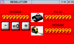
-
Premere il tasto
 (Out analogica +1 Volt), controllare che il valore del campo ENCODER aumenti
 -
Premere il tasto
 (Out analogica -1 Volt), controllare che il valore del campo ENCODER diminuisca
 -
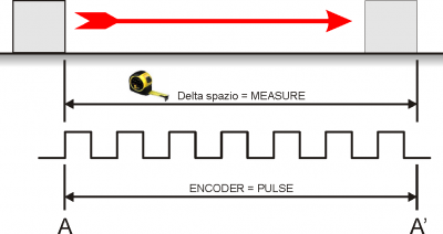
A - A' = Spazio più lungo possibile
-
Segnare la posizione di partenza (A)
-
Azzerare il valore ENCODER:

-
Eseguire il movimento da A ad A'
-
Trascrivere nel campo PULSE, il valore visualizzato nel campo ENCODER
-
Misurare il delta spazio A - A'
-
Scrivere il valore di delta spazio A - A' nel campo MEASURE
Importante:
-
Il valore di PULSE dovrà sempre essere superiore al valore di MEASURE (il valore ottimale è “MEASURE x 10 = PULSE”)
-
Introdurre il valore MEASURE nell'unità di misura scelta. Esempio: se l'unità di misura scelta è 1/10mm e la misura di delta spazio è 133.5mm, introdurre il valore 1335 nel campo MEASURE
-
I valori di Pulse e Misure qui inseriti , verranno trascritti automaticamente nei parametri GP-XX
3.6.2 Taratura P.I.D.
| P.I.D. | |
Descrivere i pulsanti e i parametri
3.6.3 Linearizzazione
| LINEARIZATION | |
Descrivere i parametri e come eseguire la linearizzazione dell'encoder quando non è in asse con il centro banco
Inserire pulsante “ Abilitazioni ”
Inserire descrizione delle abilitazioni …ovvero come è stata costruita la macchina vedi pagine iniziali sui tipi di macchine che si possono costruire con questa apparecchiatura
Poi , descrivere come caricare i default
Indicare come settare i parametri che sono specifici per la meccanica predisposta per questa macchina
Quindi si dovrà indicare come verificare gli ingressi e le uscite
4. Diagnostics
4.1 CPU DATA
 | Fw name : firmware in the controller and relative checksum Task time : the average cycle time of the CPU with indexing of the Maximum Time and the Minimum Time for the scan CPU time : total time from when the CPU is in the RUN state (hh:mm) |
4.2 Inputs
| INPUTS | |
 | Visualizzazione dello stato degli ingressi digitali suddivisi per connettore |
 | Visualizzazione del valore degli ingressi analogici |
 | Visualizzazione del valore dell'ingresso BOURNS |
4.3 Outputs
| OUTPUTS | | Visualizzazione dello stato delle uscite digitali suddivise per connettore. |
4.4 Counters
| COUNTERS | |
 | Posizioni di ogni asse in unità di misura lineare o angolare |
 | Stato di attivazione delle fasi encoder. |
 | FOLLERR: = errore di inseguimento attuale MAX: POS:/NEG: = valore minimo e massimo raggiunti dall'errore di inseguimento |
4.5 Analog outputs
| ANALOG OUTS | | Valore di tensione dell'uscita analogica |
★ Sostituire la pagina con quella riportata adattandola a questa specifica applicazione ( presa dalla levigatrice )
★ Scrivere : “ Controllare tutti gli ingressi digitali “
Per risparmiare ingressi ho modificato gli ingressi dei fine corsa degli assi
Per ogni asse non ci sono più due ingressi ma bensì uno solo …a mio avviso più che sufficiente
Poi , ho modificato i Jog …a mio avviso …utilizzando il portale ho visto che è facile sbagliare
è meglio selezionare l'asse e avere una unica interrutore a leva per movimentarlo …questo, a mio avviso favorisce il non fare errori
Poi , non è serio che lo Start e lo Stop macchina sia sullo strumento …quindi ho previsto due ingressi dedicati
Poi , ho modificato gli ingressi di Feedback dell'asse W e Asse H
…spostandoli dalle fasi encoder a degli ingressi digitali.
Nota : quando l'asse H è manuale ….per il feedback del punzone potremo utilizzare i fine corsa 24 e 25 …liberando cosi l'ingresso 23
A questo punto ..rivisti gli ingressi …potremo avere due ingressi liberi …il 23 e il 32 …e le fasi encodere potremo riservarle solo per casi particolari
4.6 Controllo dei finecorsa
Controllo dei finecorsa hardware
Controllo dei finecorsa 0° - 90° del disco
5. Hardware and connections
5.0.1 I/O List
5.0.1.1 Ingressi digitali (n. 32)
| NOME | DESCRIZIONE | MORSETTO | HARDWARE |
|---|---|---|---|
| I 1 | JOG X + (move X in + direction) | CN11 | J1K31-FR30 |
| I 2 | JOG X - (move X in - direction) | ||
| I 3 | JOG Y + (move Y in + direction) | ||
| I 4 | JOG Y - (move Y in - direction) | ||
| I 5 | JOG Z + (move Z in + direction / up) | ||
| I 6 | JOG Z - (move Z in - direction / down) | ||
| I 7 | Start work | ||
| I 8 | Stop work | ||
| I 9 | Enable manual state | CN12 | J1K31-FR30 |
| I 10 | Enable automatic state | ||
| I 11 | Reset work and zero axes | ||
| I 12 | High speed JOG. (ON = high, LOW = slow) | ||
| I 13 | Water pressure OK | ||
| I 14 | Auxiliary OK | ||
| I 15 | Splindle speed ok | ||
| I 16 | Rotation table W in working position | ||
| I 17 | Drivers OK | CN13 | J1K31-FR30 |
| I 18 | Perimetral protection OK | ||
| I 19 | X limit switch | ||
| I 20 | Y limit switch | ||
| I 21 | Z limit switch | ||
| I 22 | Feedback for unlock position 1 (usually 0°) axis W | ||
| I 23 | Feedback for unlock position 1 (usually 90°) axis W | ||
| I 24 | Y position OK for tilting table | ||
| I 25 | Horizontal disk | ||
| I 26 | Vertical disk | CN14 | J1K31-FR30 |
| I 27 | X Homing Switch | ||
| I 28 | Y Homing Switch | ||
| I 29 | Z Homing Switch | ||
| I 30 | W Homing Switch | ||
| I 31 | H Homing Switch | ||
| I 32 | free |
5.0.1.2 Ingressi digitali veloci (n. 4)
| NOME | DESCRIZIONE | MORSETTO | HARDWARE |
|---|---|---|---|
| I01 | Turn revolution sensor | CN11 | J1K31-FR30 |
| I02 | Mill inverter on | CN12 | |
| I03 | Disk inverter on | CN13 | |
| I04 | Inverter ok | CN14 |
5.0.1.3 Ingressi digitali index (n. 1)
| NOME | DESCRIZIONE | MORSETTO | HARDWARE |
|---|---|---|---|
| IDX | free | CN20 | J1K31-FR30 |
5.0.1.4 Digital outputs (n. 32)
| NAME | DESCRIPTION | TERMINAL | HARDWARE |
|---|---|---|---|
| O1 | Automatic cycle active state | CN7 | J1K31-FR30 |
| O2 | free | ||
| O3 | Alarm sound (active according with PG-09 parameter) | ||
| O4 | Rotary table high | ||
| O5 | Rotary table low | ||
| O6 | free | ||
| O7 | Enable X axis | ||
| O8 | Laser 2 | ||
| O9 | Enable Y axis | CN8 | J1K31-FR30 |
| O10 | Break Y axis | ||
| O11 | Enable Z axis | ||
| O12 | Break Z axis | ||
| O13 | Enable W axis | ||
| O14 | Enable movment W axis | ||
| O15 | Break W axis | ||
| O16 | Enable H axis | ||
| O17 | Enable movment H axis | CN9 | J1K31-FR30 |
| O18 | Break H axis | ||
| O19 | EV water | ||
| O20 | Laser 1 | ||
| O21 | Reset drive. (Active for 2 sec when reset active alarms) | ||
| O22 | free | ||
| O23 | End automatic work | ||
| O24 | Machine OK (active if alarm state is not active) | ||
| O25 | Enable Mill inverter | CN10 | J1K31-FR30 |
| O26 | Enable Disk inverter | ||
| O27 | Electrocoil to unlock perimetral protections | ||
| O28 | free | ||
| O29 | Active lock position 1 (usually 0°) for W axis | ||
| O30 | Active lock position 2 (usually 90°)for W axis | ||
| O31 | Active lock position 1 (usually 0°) for H axis | ||
| O32 | Active lock position 2 (usually 90°)for H axis |
5.0.1.5 Quadrature encoder inputs (n° 8)
| Nome | Description | Connector | Hardware |
|---|---|---|---|
| CNT01 | position X | CN15 | J1K31-FR30 |
| CNT02 | position Y | CN16 | |
| CNT03 | position Z | CN17 | |
| CNT04 | position W | CN18 | |
| CNT05 | position H | CN19 | |
| CNT06 | interpolation override burns | CN20 | |
| CNT07 (*) | free | CN21 | |
| CNT08 (*) | free | CN22 |
(*) Not available in FR hardware version
5.0.1.6 Analog inputs (n. 4)
| Name | Description | Connector | Hardware |
|---|---|---|---|
| AI1 | Potentiometer to set the X speed in cut direction | CN28 | J1K31-FR30 |
| AI2 | Potentiometer to set the X speed in opposite cut direction | ||
| AI3 | Spindle motor actual current | CN29 | |
| AI4 | Spindle actual rotation speed |
5.0.1.7 Analog outputs (n. 8)
| Nome | Description | Connector | Hardware |
|---|---|---|---|
| AO1 | X Speed | CN26 | J1K31-FR30 |
| AO2 | Y Speed | ||
| AO3 | Z Speed | ||
| AO4 | W Speed | ||
| AO5 | H Speed | CN27 | J1K31-FR30 |
| AO6 | Spindle rotation speed set | ||
| AO7 (*) | free | ||
| AO8 (*) | free |
(*) Not available in FR hardware version
( 1 ) or horizontal disk if parameter PH3 ENCODER is zero
( 2 ) or vertical disk if parameter PH3 ENCODER is zero
Note
★ NC - O significa contatto Normalmente chiuso ( Closed ) , l'azione verrà fatta quando il contatto si apre ( Open )
★ NO - C significa contatto Normalmente aperto ( Open ) , l'azione verrà fatta quando il contatto si chiude ( Closed )
★ NO - C significa contatto Normalmente aperto ( Open ), l'azione verrà fatta quando il contatto si chiude ( Closed ) in modo continuo (Continuous )
Uscite digitali
5.0.1.8 Center
Press 

 | START |
| CALC |
| SALVA |
Questa pagina offre uno strumento per poter correggere le quote X e Y della posizione del centro banco.
Una volta visualizzata questa pagina le coordinate X e Y del centro banco verranno copiate rispettivamente in PC01 e PC02.
Le fasi da seguire sono le seguenti:
-
Selezionare la modalità manuale.
-
Assicurarsi che l'asse Z sia stato azzerato sulla superficie da incidere. Eventualmente accedere alla pagina di manuale per farlo.
-
Avviare il disco e attendere che sia arrivato in velocità.
-
Toccare il tasto START sul display e lasciar eseguire l'incisione dei 5 tagli come mostrato in figura. Le incisioni dei lati del quadrato verranno eseguite alla profondità specificata nel parametro Z. L'incisione centrale verrà eseguita a profondità fissa di 5 mm.
-
Una volta eseguita l'incisione si devono eseguire le 3 misure indicate e si devono scrivere nei parametri PC03, PC04, PC05.
-
A questo punto si può premere il tasto CALC sul display per eseguire le correzioni. Si noteranno i valori PC01 e PC02 cambiare. Il tasto CALC può essere usato una sola volta e quindi se si vogliono modificare le misure inserite e ricalcolare le correzioni, bisogna uscire dalla pagina e rientrare.
-
Se si accetta la correzione, allora si devono salvare i nuovi valori premendo il tasto SAVE. Si uscirà automaticamente dalla pagina.
-
A questo punto è possibile rientrare in questa pagina ed eseguire ancora l'incisione (punti 1, 2 e 3) per verificare che PC03 e PC04 siano tra loro uguali e PC05 sia pari a L mm.
| Nome parametro | Unità di misura | Default | Range | Descrizione |
|---|---|---|---|---|
| PC01 : X CENTER | mm | 1699.10 | 0÷999999.99 | Copia della coordinata X del centro del banco. |
| PC02 : Y CENTER | mm | 1765.60 | 0÷999999.99 | Copia della coordinata Y del centro del banco. |
| PC03 : | mm | 0.00 | -999.99 ÷ 999.99 | Misure come da disegno per la correzione della coordinata X del centro. |
| PC04 : | mm | 0.00 | -999.99 ÷ 999.99 | |
| PC05 : | mm | 0.00 | 0÷9999.99 | Misure come da disegno per la correzione della coordinata Y del centro. |
| L: | mm | 200.00 | 0÷999999.99 | Lato L dell'incisione praticata. |
| Z: | mm | 5.00 | 0÷999999.99 | Profondità del taglio dei lati |
Press  to exit
5.1 Enable
Premere il pulsante nell'area 1.
