Indice
12-Head Standard Polishing Machine: Wiring connections

| Document | mce_p1p51fc20-008 | ||
|---|---|---|---|
| Description | Wiring connections for 12-Head Standard Polishing Machine | ||
| Drawn up | Davide Mocellin | ||
| Approved | Gabriele Bazzi | ||
| Link | http://www.qem.eu/doku/doku.php/en/applicazioni/marmo/levigatrice_di_lastre/standard_12_heads/mce_standard_12_heads | ||
| Language | English | ||
| Document Release | Description | Notes | Date |
| 01 | New manual | 20/11/2014 | |
All rights reserved on this manual. No part of this document can be copied or reproduced in any form without prior written authorisation. QEM does not insure or guarantee its contents and explicitly declines all liability related to the guarantee of its suitability for any purpose. The information in this document can be changed without notice. QEM shall not be held liable for any error or omission in this document. QEM® is a registered trademark.Microsoft® and MS-DOS® are registered trademarks and Windows® is a trademark of Microsoft Corporation.
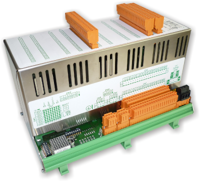
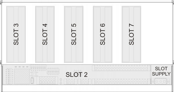
1. Hardware
1.1 Operator Panel
| J1-P51-FC20/TP03 | |
|---|---|
 |
|
 |
|
 | MIMJ1P51Fx:Installation and Maintenance Manual |
1.2 Remote modules inputs/outputs


2. I/O Resources
2.1 Digital Inputs
-
NO = Normally Opened
-
NC = Normally Closed
-
PR = Programmable
-
I = Impulsive
-
C = Continuous
| NAME | DESCRIPTION | LOGIC | TERMINAL | HARDWARE | |||
|---|---|---|---|---|---|---|---|
| - | Not used |  | CN11.1 | J1-P51 | |||
| - | Not used | CN11.2 | |||||
| 0V | Common for digital inputs | CN11.3 | |||||
| I1 | Emergency | NC | C | 0 = emergency 1 = machine ok | CN11.4 | ||
| I2 | Beam: Forward Jog | NO | C | 1 = jog active | CN11.5 | ||
| I3 | Beam: Backward Jog | NO | C | 1 = jog active | CN11.6 | ||
| I4 | START pushbutton | NO | I | 1 = start action | CN11.7 | ||
| I5 | STOP pushbutton | NO | I | 1 = stop action | CN11.8 | ||
| I6 | Change Abrasive pushbutton | NO | I | 1 = change abrasive action | CN11.9 | ||
| I7 | Manual selector | NO | C | 0 = not in manual 1 = selector in manual | CN11.10 | ||
| I8 | Automatic selector | NO | C | 0 = not in automatic 1 = selector in automatic | CN11.11 | ||
| 0V | Common for digital inputs | CN11.12 | |||||
| - | Not used | | CN12.1 | J1-P51 | |||
| - | Not used | CN12.2 | |||||
| 0V | Common for digital inputs | CN12.3 | |||||
| I9 | STAND-BY | NO | I | 1 = stand-by action | CN12.4 | ||
| I10 | Enclosure | NC | C | 0 = enclosure opened 1 = enclosure closed | CN12.5 | ||
| I11 | Beam Fault | NC | C | 0 = beam fault 1 = beam ok | CN12.6 | ||
| I12 | Belt Fault | NC | C | 0 = belt fault 1 = belt ok | CN12.7 | ||
| I13 | Roller Fault | NC | C | 0 = roller fault 1 = roller ok | CN12.8 | ||
| I14 | Beam Forward LS | NC | C | 0 = beam in forward LS | CN12.9 | ||
| I15 | Beam Backward LS | NC | C | 0 = beam in backward LS | CN12.10 | ||
| I16 | Beam Zero sensor | NO | I | 1 = beam over zero sensor | CN12.11 | ||
| 0V | Common for digital inputs | CN12.12 | |||||
| | | | | | | | |
| NAME | DESCRIPTION | LOGIC | TERMINAL | HARDWARE | |||
|---|---|---|---|---|---|---|---|
| +24V | OUT 24Volt |  | CN2.1 | RMC-2M | |||
| 0V | 0V out 24V | CN2.2 | |||||
| I17 | Head-1: Local Man/Aut | NC | C | 0 = manual 1 = auto | CN2.3 | ||
| I18 | Head-1: Local Jog | NO | C | 0 = head up 1 = head down | CN2.4 | ||
| I19 | Head-2: Local Man/Aut | NC | C | 0 = manual 1 = auto | CN2.5 | ||
| I20 | Head-2: Local Jog | NO | C | 0 = head up 1 = head down | CN2.6 | ||
| I21 | Head-3: Local Man/Aut | NC | C | 0 = manual 1 = auto | CN2.7 | ||
| I22 | Head-3: Local Jog | NO | C | 0 = head up 1 = head down | CN2.8 | ||
| I23 | Head-4: Local Man/Aut | NC | C | 0 = manual 1 = auto | CN2.9 | ||
| I24 | Head-4: Local Jog | NO | C | 0 = head up 1 = head down | CN2.10 | ||
| +24V | OUT 24Volt | CN2.11 | |||||
| 0V | 0V out 24V | CN2.12 | |||||
| I25 | Head-5: Local Man/Aut | NC | C | 0 = manual 1 = auto | CN2.13 | ||
| I26 | Head-5: Local Jog | NO | C | 0 = head up 1 = head down | CN2.14 | ||
| I27 | Head-6: Local Man/Aut | NC | C | 0 = manual 1 = auto | CN2.15 | ||
| I28 | Head-6: Local Jog | NO | C | 0 = head up 1 = head down | CN2.16 | ||
| I29 | Head-7: Local Man/Aut | NC | C | 0 = manual 1 = auto | CN2.17 | ||
| I30 | Head-7: Local Jog | NO | C | 0 = head up 1 = head down | CN2.18 | ||
| I31 | Head-8: Local Man/Aut | NC | C | 0 = manual 1 = auto | CN2.19 | ||
| I32 | Head-8: Local Jog | NO | C | 0 = head up 1 = head down | CN2.20 | ||
| +24V | OUT 24Volt | | CN3.1 | ||||
| 0V | 0V out 24V | CN3.2 | |||||
| I33 | Head-9: Local Man/Aut | NC | C | 0 = manual 1 = auto | CN3.3 | ||
| I34 | Head-9: Local Jog | NO | C | 0 = head up 1 = head down | CN3.4 | ||
| I35 | Head-10: Local Man/Aut | NC | C | 0 = manual 1 = auto | CN3.5 | ||
| I36 | Head-10: Local Jog | NO | C | 0 = head up 1 = head down | CN3.6 | ||
| I37 | Head-11: Local Man/Aut | NC | C | 0 = manual 1 = auto | CN3.7 | ||
| I38 | Head-11: Local Jog | NO | C | 0 = head up 1 = head down | CN3.8 | ||
| I39 | Head-12: Local Man/Aut | NC | C | 0 = manual 1 = auto | CN3.9 | ||
| I40 | Head-12: Local Jog | NO | C | 0 = head up 1 = head down | CN3.10 | ||
| +24V | OUT 24Volt | CN3.11 | |||||
| 0V | 0V out 24V | CN3.12 | |||||
| I41 | Not used | CN3.13 | |||||
| I42 | Not used | CN3.14 | |||||
| I43 | Heads: cutouts | NC | C | 0 = cutouts alarm 1 = cutouts ok | CN3.15 | ||
| I44 | Air Pressure | NC | C | 0 = air pressure alarm 1 = pressure ok | CN3.16 | ||
| I45 | Water Pressure | NC | C | 0 = water pressure alarm 1 = pressure ok | CN3.17 | ||
| I46 | Change abrasive sensor | NO | I | 1 = change abrasive action | CN3.18 | ||
| I47 | Roller Slab sensor at end | NO | I | 1 = slab over roller sensor | CN3.19 | ||
| I48 | Belt Slab sensor at start | NO | I | 1 = slab over belt sensor | CN3.20 | ||
| | | | | | | | |
| +24V | OUT 24Volt | | SLOT3.1A | RMC-2M | |||
| 0V | 0V out 24V | SLOT3.2A | |||||
| I49 | Bar sensor 1 | PR | C | SLOT3.3A | |||
| I50 | Bar sensor 2 | PR | C | SLOT3.4A | |||
| I51 | Bar sensor 3 | PR | C | SLOT3.5A | |||
| I52 | Bar sensor 4 | PR | C | SLOT3.6A | |||
| I53 | Bar sensor 5 | PR | C | SLOT3.7A | |||
| I54 | Bar sensor 6 | PR | C | SLOT3.8A | |||
| I55 | Bar sensor 7 | PR | C | SLOT3.9A | |||
| I56 | Bar sensor 8 | PR | C | SLOT3.10A | |||
| +24V | OUT 24Volt | SLOT3.11A | |||||
| 0V | 0V out 24V | SLOT3.12A | |||||
| I57 | Bar sensor 9 | PR | C | SLOT3.13A | |||
| I58 | Bar sensor 10 | PR | C | SLOT3.14A | |||
| I59 | Bar sensor 11 | PR | C | SLOT3.15A | |||
| I60 | Bar sensor 12 | PR | C | SLOT3.16A | |||
| I61 | Bar sensor 13 | PR | C | SLOT3.17A | |||
| I62 | Bar sensor 14 | PR | C | SLOT3.18A | |||
| I63 | Bar sensor 15 | PR | C | SLOT3.19A | |||
| I64 | Bar sensor 16 | PR | C | SLOT3.20A | |||
| +24V | OUT 24Volt | | SLOT3.1B | ||||
| 0V | 0V out 24V | SLOT3.2B | |||||
| I65 | Bar sensor 17 | PR | C | SLOT3.3B | |||
| I66 | Bar sensor 18 | PR | C | SLOT3.4B | |||
| I67 | Bar sensor 19 | PR | C | SLOT3.5B | |||
| I68 | Bar sensor 20 | PR | C | SLOT3.6B | |||
| I69 | Bar sensor 21 | PR | C | SLOT3.7B | |||
| I70 | Bar sensor 22 | PR | C | SLOT3.8B | |||
| I71 | Bar sensor 23 | PR | C | SLOT3.9B | |||
| I72 | Bar sensor 24 | PR | C | SLOT3.10B | |||
| +24V | OUT 24Volt | SLOT3.11B | |||||
| 0V | 0V out 24V | SLOT3.12B | |||||
| I73 | Bar sensor 25 | PR | C | SLOT3.13B | |||
| I74 | Bar sensor 26 | PR | C | SLOT3.14B | |||
| I75 | Bar sensor 27 | PR | C | SLOT3.15B | |||
| I76 | Bar sensor 28 | PR | C | SLOT3.16B | |||
| I77 | Bar sensor 29 | PR | C | SLOT3.17B | |||
| I78 | Bar sensor 30 | PR | C | SLOT3.18B | |||
| I79 | Bar sensor 31 | PR | C | SLOT3.19B | |||
| I80 | Bar sensor 32 | PR | C | SLOT3.20B | |||
| | | | | | | |
|
| NAME | DESCRIPTION | LOGIC | TERMINAL | HARDWARE | |||
|---|---|---|---|---|---|---|---|
| +24V | OUT 24Volt | | SLOT4.1A | RMC-2M | |||
| 0V | 0V out 24V | SLOT4.2A | |||||
| I81 | Bar sensor 33 | PR | C | SLOT4.3A | |||
| I82 | Bar sensor 34 | PR | C | SLOT4.4A | |||
| I83 | Bar sensor 35 | PR | C | SLOT4.5A | |||
| I84 | Bar sensor 36 | PR | C | SLOT4.6A | |||
| I85 | Bar sensor 37 | PR | C | SLOT4.7A | |||
| I86 | Bar sensor 38 | PR | C | SLOT4.8A | |||
| I87 | Bar sensor 39 | PR | C | SLOT4.9A | |||
| I88 | Bar sensor 40 | PR | C | SLOT4.10A | |||
| +24V | OUT 24Volt | SLOT4.11A | |||||
| 0V | 0V out 24V | SLOT4.12A | |||||
| I89 | Bar sensor 41 | PR | C | SLOT4.13A | |||
| I90 | Bar sensor 42 | PR | C | SLOT4.14A | |||
| I91 | Bar sensor 43 | PR | C | SLOT4.15A | |||
| I92 | Bar sensor 44 | PR | C | SLOT4.16A | |||
| I93 | Bar sensor 45 | PR | C | SLOT4.17A | |||
| I94 | Bar sensor 46 | PR | C | SLOT4.18A | |||
| I95 | Bar sensor 47 | PR | C | SLOT4.19A | |||
| I96 | Bar sensor 48 | PR | C | SLOT4.20A | |||
| +24V | OUT 24Volt | | SLOT4.1B | ||||
| 0V | 0V out 24V | SLOT4.2B | |||||
| I97 | Bar sensor 49 | PR | C | SLOT4.3B | |||
| I98 | Bar sensor 50 | PR | C | SLOT4.4B | |||
| I99 | Bar sensor 51 | PR | C | SLOT4.5B | |||
| I100 | Bar sensor 52 | PR | C | SLOT4.6B | |||
| I101 | Bar sensor 53 | PR | C | SLOT4.7B | |||
| I102 | Bar sensor 54 | PR | C | SLOT4.8B | |||
| I103 | Bar sensor 55 | PR | C | SLOT4.9B | |||
| I104 | Bar sensor 56 | PR | C | SLOT4.10B | |||
| +24V | OUT 24Volt | SLOT4.11B | |||||
| 0V | 0V out 24V | SLOT4.12B | |||||
| I105 | Bar sensor 57 | PR | C | SLOT4.13B | |||
| I106 | Bar sensor 58 | PR | C | SLOT4.14B | |||
| I107 | Bar sensor 59 | PR | C | SLOT4.15B | |||
| I108 | Bar sensor 60 | PR | C | SLOT4.16B | |||
| I109 | Bar sensor 61 | PR | C | SLOT4.17B | |||
| I110 | Bar sensor 62 | PR | C | SLOT4.18B | |||
| I111 | Bar sensor 63 | PR | C | SLOT4.19B | |||
| I112 | Bar sensor 64 | PR | C | SLOT4.20B | |||
| | | | | | | |
|
2.2 Digital Outputs
-
I = Impulsive
-
C = Continuous
-
PR = Programmable
| NAME | DESCRIPTION | LOGIC | TERMINAL | HARDWARE | ||
|---|---|---|---|---|---|---|
| V+ | Voltage Input (12÷28 Vdc) |  | CN15.1 | J1-P51 | ||
| O1 | AUTOMATIC ON light | C | 1 = light on | CN15.2 | ||
| O2 | ALARM light | C | 1 = light on | CN15.3 | ||
| V- | Common Voltage input (0V) | CN15.4 | ||||
| O3 | PRE-START light | C | 1 = light on | CN15.5 | ||
| O4 | RUN light | 1 = light on | CN15.6 | |||
| V- | Common Voltage input (0V) | CN15.7 | ||||
| O5 | Beam enable | 1 = beam enable | CN15.8 | |||
| O6 | Not used | CN15.9 | ||||
| O7 | Belt forward enable | I/C | 1 = belt run | CN15.10 | ||
| O8 | Belt stop | I | 1 = belt stopped | CN15.11 | ||
| V+ | Voltage Input (12÷28 Vdc) | | CN16.1 | |||
| O9 | Roller start | C | 1 = roller run | CN16.2 | ||
| O10 | Brush Up/Down | C | 0 = brush up 1 = brush down | CN16.3 | ||
| V- | Common Voltage input (0V) | CN16.4 | ||||
| O11 | Upline machine consensus | C | 1 = upline machine run | CN16.5 | ||
| O12 | Lubrification | C | 1 = lubrification on | CN16.6 | ||
| V- | Common Voltage input (0V) | CN16.7 | ||||
| O13 | Spray On/Off | C | 0 = spray off 1 = spray on | CN16.8 | ||
| O14 | Belt backward enable | I/C | 1 = belt run | CN16.9 | ||
| O15 | Not used | CN16.10 | ||||
| O16 | Not used | CN16.11 | ||||
| | | | | | | |
| NAME | DESCRIPTION | LOGIC | TERMINAL | HARDWARE | ||
|---|---|---|---|---|---|---|
| V+ | Voltage input 12÷28 Vdc | | SLOT6.1A | RMC-2M | ||
| V- | SLOT6.2A | |||||
| O17 | Head 1: Start | C | 1 = motor on | SLOT6.3A | ||
| O18 | Head 1: Up | C | 1 = head up | SLOT6.4A | ||
| O19 | Head 1: Down | C | 1 = head down | SLOT6.5A | ||
| O20 | Head 2: Start | C | 1 = motor on | SLOT6.6A | ||
| O21 | Head 2: Up | C | 1 = head up | SLOT6.7A | ||
| O22 | Head 2: Down | C | 1 = head down | SLOT6.8A | ||
| O23 | Head 3: Start | C | 1 = motor on | SLOT6.9A | ||
| O24 | Head 3: Up | C | 1 = head up | SLOT6.10A | ||
| V+ | Voltage input 12~28 Vdc | SLOT6.11A | ||||
| V- | SLOT6.12A | |||||
| O25 | Head 3: Down | C | 1 = head down | SLOT6.13A | ||
| O26 | Head 4: Start | C | 1 = motor on | SLOT6.14A | ||
| O27 | Head 4: Up | C | 1 = head up | SLOT6.15A | ||
| O28 | Head 4: Down | C | 1 = head down | SLOT6.16A | ||
| O29 | Head 5: Start | C | 1 = motor on | SLOT6.17A | ||
| O30 | Head 5: Up | C | 1 = head up | SLOT6.18A | ||
| O31 | Head 5: Down | C | 1 = head down | SLOT6.19A | ||
| O32 | Head 6: Start | C | 1 = motor on | SLOT6.20A | ||
| V+ | Voltage input 12~28 Vdc | | SLOT6.1B | |||
| V- | SLOT6.2B | |||||
| O33 | Head 6: Up | C | 1 = head up | SLOT6.3B | ||
| O34 | Head 6: Down | C | 1 = head down | SLOT6.4B | ||
| O35 | Head 7: Start | C | 1 = motor on | SLOT6.5B | ||
| O36 | Head 7: Up | C | 1 = head up | SLOT6.6B | ||
| O37 | Head 7: Down | C | 1 = head down | SLOT6.7B | ||
| O38 | Head 8: Start | C | 1 = motor on | SLOT6.8B | ||
| O39 | Head 8: Up | C | 1 = head up | SLOT6.9B | ||
| O40 | Head 8: Down | C | 1 = head down | SLOT6.10B | ||
| V+ | Voltage input 12~28 Vdc | SLOT6.11B | ||||
| V- | SLOT6.12B | |||||
| O41 | Head 9: Start | C | 1 = motor on | SLOT6.13B | ||
| O42 | Head 9: Up | C | 1 = head up | SLOT6.14B | ||
| O43 | Head 9: Down | C | 1 = head down | SLOT6.15B | ||
| O44 | Head 10: Start | C | 1 = motor on | SLOT6.16B | ||
| O45 | Head 10: Up | C | 1 = head up | SLOT6.17B | ||
| O46 | Head 10: Down | C | 1 = head down | SLOT6.18B | ||
| O47 | Head 11: Start | C | 1 = motor on | SLOT6.19B | ||
| O48 | Head 11: Up | C | 1 = head up | SLOT6.20B | ||
| V+ | Voltage input 12~28 Vdc | | SLOT7.1A | |||
| V- | SLOT7.2A | |||||
| O49 | Head 11: Down | C | 1 = head up | SLOT7.3A | ||
| O50 | Head 12: Start | C | 1 = motor on | SLOT7.4A | ||
| O51 | Head 12: Up | C | 1 = head up | SLOT7.5A | ||
| O52 | Head 12: Down | C | 1 = head down | SLOT7.6A | ||
| O53~O64 | Not used | |||||
| O65~O76 | Not used | |||||
| | | | | | | |
2.3 Two-way Encoder Count Inputs
| Beam Encoder Push-Pull |
||||
|---|---|---|---|---|
| NAME | DESCRIPTION | TERMINAL | HARDWARE | |
| - | Not used |  | CN7.1A | J1-P51 |
| PHA1 | Phase A | CN7.2A | ||
| PHB1 | Phase B | CN7.3A | ||
| Z1 | Z | CN7.4A | ||
| ∩ | Connect to terminal 5B | CN7.5A | ||
| ∩ | Connect to terminal 6B | CN7.6A | ||
| 0V ∩ | Common for count inputs Connect to terminal 7B | CN7.7A | ||
| - | Not used | CN7.1B | ||
| - | CN7.2B | |||
| - | CN7.3B | |||
| - | CN7.4B | |||
| ∩ | Connect to terminal 5A | CN7.5B | ||
| ∩ | Connect to terminal 6A | CN7.6B | ||
| ∩ | Connect to terminal 7A | CN7.7B | ||
| | | | |
|
| Belt Encoder Push-Pull |
||||
|---|---|---|---|---|
| NAME | DESCRIPTION | TERMINAL | HARDWARE | |
| - | Not used | | CN8.1A | J1-P51 |
| PHA2 | Phase A | CN8.2A | ||
| PHB2 | Phase B | CN8.3A | ||
| Z2 | Z | CN8.4A | ||
| ∩ | Connect to terminal 5B | CN8.5A | ||
| ∩ | Connect to terminal 6B | CN8.6A | ||
| 0V ∩ | Common for count inputs Connect to terminal 7B | CN8.7A | ||
| - | Not used | CN8.1B | ||
| - | CN8.2B | |||
| - | CN8.3B | |||
| - | CN8.4B | |||
| ∩ | Connect to terminal 5A | CN8.5B | ||
| ∩ | Connect to terminal 6A | CN8.6B | ||
| ∩ | Connect to terminal 7A | CN8.7B | ||
| | | | |
|
2.4 Analog Outputs
| NAME | DESCRIPTION | TERMINAL | HARDWARE | |
|---|---|---|---|---|
| GAO | Common for analog outputs |  | CN17.1 | J1-P51 |
| AO1 | Beam speed control ±10Vdc | CN17.2 | ||
| AO2 | Belt speed control 0+10Vdc | CN17.3 | ||
| GAO | Not used | CN17.4 | ||
| AO3 | Not used | CN17.5 | ||
| AO4 | Not used | CN17.6 | ||
| | | | |
|