~~BOZZA~~
RMC-2M - Manuale di installazione e manutenzione


Modulo di I/O con protocollo di comunicazione ![]()
1. Informazioni
| Documento: | MIMRMC2M | ||
|---|---|---|---|
| Descrizione: | Manuale di installazione e manutenzione | ||
| Redattore: | Riccardo Furlato | ||
| Approvatore | Gabriele Bazzi | ||
| Link: | http://www.qem.eu/doku/doku.php/strumenti/moduli/rmc2m/mimrmc2m | ||
| Lingua: | Italiano | ||
| Release documento | Descrizione | Note | Data |
| 01 | Nuovo manuale | 04/06/2014 | |
The controller has been designed for industral environments in conformity to EC directive 2004/108/CE.
-
EN 61000-6-4: Electromagnetic compatibility - Generic standard on emission for industrial environments
-
EN55011 Class A: Limits and measurement methods
-
EN 61000-6-2: Electromagnetic compatibility - Generic standard on immunity for industrial environments
-
EN 61000-4-2: Electromagnetic compatibility - Electrostatic discharge immunity
-
EN 61000-4-3: Immunity to radiated, radio-frequency electromagnetic field
-
EN 61000-4-4: Electrical fast transients
-
EN 61000-4-5: Surge immunity
-
EN 61000-4-6: Conducted disturbance induced by radio-frequency
-
Moreover the product is conform to the following standards:
-
EN 60529: Housing protection rating IP64
-
EN 60068-2-1: Environmental testing: Cold
-
EN 60068-2-2: Environmental testing: Dry heat
-
EN 60068-2-14: Environmental testing: Change of temperature
-
EN 60068-2-30: Environmental testing: Cyclic damp heat
-
EN 60068-2-6: Environmental testing: Sinusoidal vibration
-
EN 60068-2-27: Environmental testing: Shock vibration
-
EN 60068-2-64: Environmental testing: Random vibration
-
2. Descrizione
RMC-2M è un modulo di I/O con protocollo di comunicazione
 che, nella sua minima configurazione di base, può essere dotato di:
Dotazione di serie 
Protocollo di comunicazione CANopen 
64 led di diagnostica 4 led di sistema 
1 porta CANbus 1) 
32 ingressi digitali
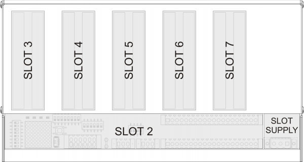
1) Con il doppio connettore per favorire il cablaggioInoltre il modulo mette a disposizione nr.5 slot per accogliere delle schede espansioni di tipo L2 e H2.
2.1 Identificazione del prodotto
In base al Codice d'ordinazione dello strumento è possibile ricavarne esattamente le caratteristiche. Verificare che le Caratteristiche dello strumento corrispondano alle Vostre esigenze.
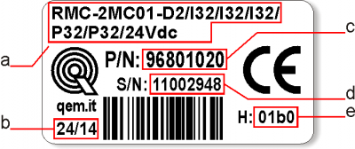
2.2 Etichetta prodotto
-
a - Ordering Code
-
b - Week made: indicates the week and year of manufacture
-
c - Part number: unique code that identifies an ordering code
-
d - Serial number: product serial number, different for individual product
-
e - Hardware release: version of hardware release
2.3 Codice di ordinazione
Modello Caratteristiche RMC - 2M C 01 - M2 / CV4 / CV2 / AI2 / I32 / P32 / 24Vdc Alimentazione P32 = Tipo di versione hardware I32 = Tipo di versione hardware AI2 = Tipo di versione hardware CV2 = Tipo di versione hardware CV4 = Tipo di scheda espansione M2 = Gamma di espansioni 01 = Versione firmware C = Ingombri esterni del modulo (267x125mm) 2M = Secondo modello della versione “M” (Multi Board) dei moduli remotati RMC = Famiglia moduli I/O remotati in CanOpen Gamma SLOT3(L2/H2) SLOT4(L2/H2) SLOT5(L2/H2) SLOT6(L2/H2) SLOT7(L2/H2) ID Note M1 CV_ CV_ AI_ DP1 P32 0 M2 CV_ CV_ AI_ I32 P32 1 M3 CV_ CV_ I32 DP1 P32 5 D1 I32 P32 P32 P32 P32 2 D2 I32 I32 I32 P32 P32 3 D3 I32 I32 P32 P32 P32 4 D4 I32 I32 DP1 P32 P32 12 G1 TM_ A12 A12 I32 P32 6 G2 TM_ TM_ AI2 P32 P32 7 G3 CV_ FI2 A16 P32 R32 8 G4 A12 A12 A12 P32 P32 9 G5 A12 A12 AP2 P32 P32 10 G6 A12 A12 G12 G12 P32 11 3. Caratteristiche tecniche
3.1 Caratteristiche generali
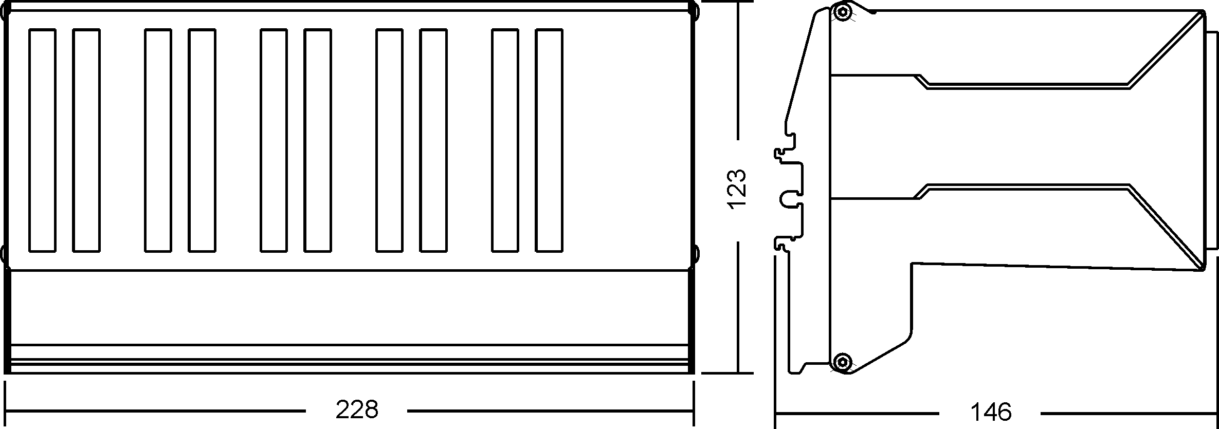
Weight (maximum hardware configuration) 500g Housing material PVC + Stainless Steel System Leds 4 Diagnostic Leds 64 System keys 1 Operating temperature 0 - 50°C Relative humidity 90% condensate free Altitude 0 - 2000m a.s.l. Transport and storage temperature -25 - +70°C Protection rating IP20 3.2 Dimensions
Lengths in mm.

3.3 Cablaggio

• Please read carefully.
• See technical notes on Weidmuller terminals BLZF, BLZ and B2L.Types of Connectors
Family Wire Section
no end capsWire section
with end capsCharacteristics
of contactTools 
BLZF 3.5 0.3-1.50 mm2 0.3-1 mm2 
Open the self-locking, spring clip terminals with a flat blade screwdriver to DIN 5264-A as shown below
See the table below for recommended cap ends
To crimp the cap ends to the wire use the tool below
B2L 3.5 0.3-1.00 mm2 0,3-0.5 mm2 
BLZF 5.08 0.3-2.50 mm2 0.3-2.00 mm2 
BLZ 5.00 0.2-2.50 mm2 0.1-1 mm2 
The screw terminals can be tightened with a flat blade screwdriver to DIN 5264 as shown in fig.4.7
Tightening torque: 0.4 - 0.5 Nm.For a safer cabling, always use wire end caps
Tools
End caps
Wire section End cap section Make Model 0.1-0.3 mm2 0.95 mm2 Cembre PKE 308 0.3-0.5 mm2 1.32 mm2 Cembre PKE 508 BM BM00601 1 mm2 2.5mm2 BM00603 PK 108 BM BM00603 End cap crimping tool
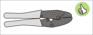 Use a crimp tool type “Cembre ND#4
cod. 2590086”
Use a crimp tool type “Cembre ND#4
cod. 2590086”
Screwdrivers
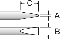 Screwdriver for opening self-locking spring clip terminals:
A = 0.6mm
B = 2.5mm max
C = 7 mm min
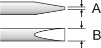 Screwdriver for tightening screw terminals:
A = 0.6mm
B = 3.5mm
Procedure
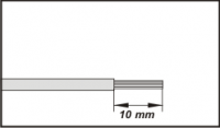
Strip 10mm of copper wire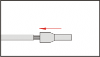
Fit the end cap and crimp it with a crimping tool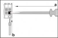
a) fit the screwdriver without turning it
b) fit the cable in the terminal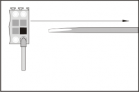
Remove the screwdriver4. Collegamenti
4.1 Power supply
-
Il cablaggio deve essere eseguito da personale specializzato e dotato degli opportuni provvedimenti antistatici.
-
Prima di maneggiare lo strumento, togliere tensione e tutte le parti ad esso collegate.
-
Per garantire il rispetto delle normative CE, la tensione d'alimentazione deve avere un isolamento galvanico di almeno 1500 Vac.
Alimentazioni disponibili 24 Vdc Range valido 22 ÷ 27 Vdc Assorbimento max. 30W 
4.1.1 Esempi di collegamento

The cabling must be carried out by specialist personnel and fitted with suitable anti-static precautions.
Before handling the controller, disconnect the power and all parts connected to it.
To guarantee compliance with EC regulations, the power supply must have a galvanic isolation of at least 1500Vac.Power supply 24 Vdc Voltage range 22 - 27 Vdc Max. absorption 30W CN1 Terminal Symbol Description 

1 L1/+ DC power positive 2 GROUND Gnd-PE (signals) 3 L2/- DC power 0V Connection examples for 24Vdc power supply
Use an isolated power unit with 24Vdc +/-5% output conform to EN60950-1. 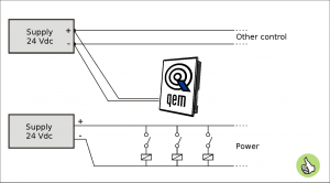
Use two separate power units: one for the control circuit and one for the power circuit 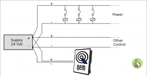
For a single power unit, use two separate lines: one for the control and one for the power 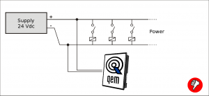
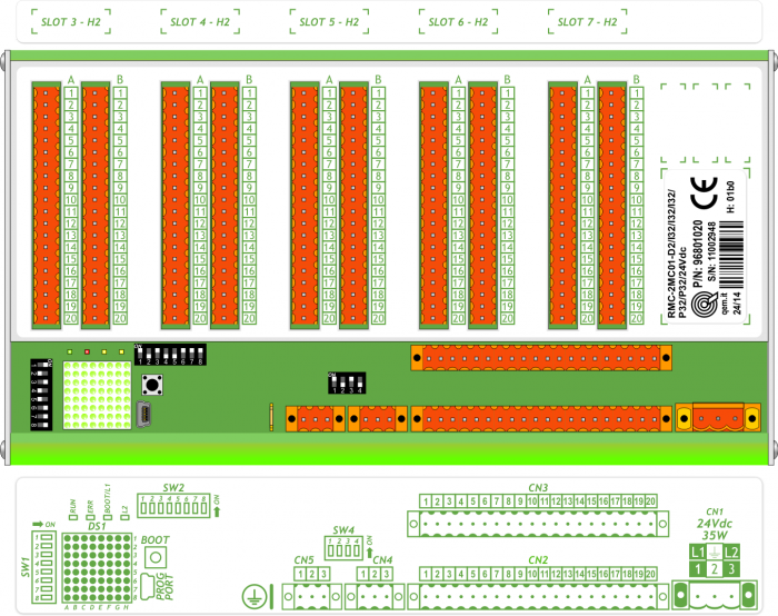
DO NOT use the same lines for the power circuit and the controller 4.2 Scheda base
4.2.1 Collegamenti seriali
CANbus PORT
Connettori CANbus PORT
CAN-IN PORT (CN4)
CAN-OUT PORT (CN5)Morsetto Simbolo Descrizione 
1 0V Comune CAN 2 CAN L Terminale CAN L 3 CAN H Terminale CAN H Settaggio resistenze di terminazione
SW4 Num.
DipNome
DipImpostazione
dei DIPFunzione 
1 JP1 ON Terminazione CAN1 2 JP2 ON 3 JP1 ON Terminazione CAN2 4 JP2 ON Per attivare la terminazione di una porta CAN, devono essere attivati entrambi i relativi DIP JP1 e JP2.
4.2.2 Ingressi digitali
32 ingressi digitali standard
Le caratteristiche elettriche sono riportate nel paragrafo Caratteristiche elettriche.
Gli esempi di collegamento sono riportati nel paragrafo Esempi di collegamentoCN2 Pin Nome Descrizione Indirizzo CN3 Pin Nome Descrizione Indirizzo 
1A +24V OUT 24Volt 1B +24V OUT 24Volt 2A 0V 0V out 24V 2B 0V 0V out 24V 3A I1 Digital inputs (PNP) X.INP01 3B I17 Digital inputs (PNP) X.INP17 4A I2 X.INP02 4B I18 X.INP18 5A I3 X.INP03 5B I19 X.INP19 6A I4 X.INP04 6B I20 X.INP20 7A I5 X.INP05 7B I21 X.INP21 8A I6 X.INP06 8B I22 X.INP22 9A I7 X.INP07 9B I23 X.INP23 10A I8 X.INP08 10B I24 X.INP24 11A +24V OUT 24Volt 11B +24V OUT 24Volt 12A 0V 0V out 24V 12B 0V 0V out 24V 13A I9 Digital inputs (PNP) X.INP09 13B I25 Digital inputs (PNP) X.INP25 14A I10 X.INP10 14B I26 X.INP26 15A I11 X.INP11 15B I27 X.INP27 16A I12 X.INP12 16B I28 X.INP28 17A I13 X.INP13 17B I29 X.INP29 18A I14 X.INP14 18B I30 X.INP30 19A I15 X.INP15 19B I31 X.INP31 20A I16 X.INP16 20B I32 X.INP32 5. Caratteristiche elettriche
Di seguito sono riportate le caratteristiche elettriche hardware.
I valori di frequenze massime e minime e tempi di acquisizione effettivi, possono comunque dipendere da eventuali filtri software aggiuntivi.5.1 PROG PORT (USB mini-B)
Il connettore USB mini-B non supporta gli standard elettrici USB, deve essere utilizzato solamente mediante una interfaccia IQ009 o IQ013. Seriale utilizzata per il trasferimento e l'aggiornamento del firmware.
Standard elettrico TTL (Usare l'interfaccia seriale IQ009 o IQ013) Velocità di comunicazione 115200 Kbaud Isolamento Nessuno .

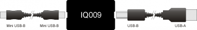

Collegamento tra Qmove+ e PC, con l'ausilio dell'accessorio IQ009 .
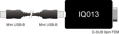

Collegamento tra Qmove+ e un dispositivo dotato di seriale RS232 (per esempio un MODEM), con l'ausilio dell'interfaccia IQ013 5.2 CANbus PORT
Per attivare la resistenza di terminazione interna vedere paragrafo Settaggio resistenze di terminazione
.
Velocità di comunicazione 125, 250, 500, 1000 Kbit/s Max. numero Driver/Receiver sulla linea 100 Max. lunghezza cavi 500m @ 125Kbit/s, 250m @ 250Kbit/s, 100m @ 500Kbit/s, 25m @ 1000Kbit/s Impedenza d'ingresso >15Kohm Limite corrente cortocircuito 45mA 


Esempio di collegamento CAN BUS.
Attenzione: chiudere i DIP JP1 e JP2 ed inserire le resistenze di terminazione (RL, RH) sull'ultimo dispositivo della catena.
5.3 Ingressi digitali
Tipo di polarizzazione PNP Tempo min. di acquisizione (hardware) 3ms Isolamento 1000Vrms Tensione di funzionamento nominale 24Vdc Tensione stato logico 0 0÷2 V Tensione stato logico 1 10,5 ÷ 26,5 V Caduta di tensione interna 5V Resistenza di ingresso (Ri) 2200Ω Corrente assorbita 2mA ÷ 10mA1)
1) ATTENZIONE: se il dispositivo collegato agli ingressi necessita di una corrente minima commutabile superiore, gli ingressi potrebbero non funzionare correttamente.
6. Esempi di collegamento
CANbus

• On the first (1) and on the last (3) device of the chain, the termination resistances must be inserted.
• The cable shoes must be connected to ground by the fastons provided on the metal body.
• To activate the internal termination resistance see paragraph Setup of CAN1 and CAN2 PORT Termination resistances Digital inputs

PNP / Push Pull count inputs

Voltmetric and amperometric analog inputs

Voltmetric and potentiometric analog inputs

Protected digital outputs

Analog outputs

6.1 CANbus
-
Sul primo (1) e sull'ultimo (3) dispositivo della catena, devono essere inserite le resistenze di terminazione.
-
La calza dei cavi deve essere connessa a terra tramite gli appositi faston presenti sulla carcassa metallica.
-
Per attivare la resistenza di terminazione interna vedere paragrafo “Resistenze di terminazione CAN”
6.2 Ingressi digitali

7. Settaggi, procedure e segnalazioni
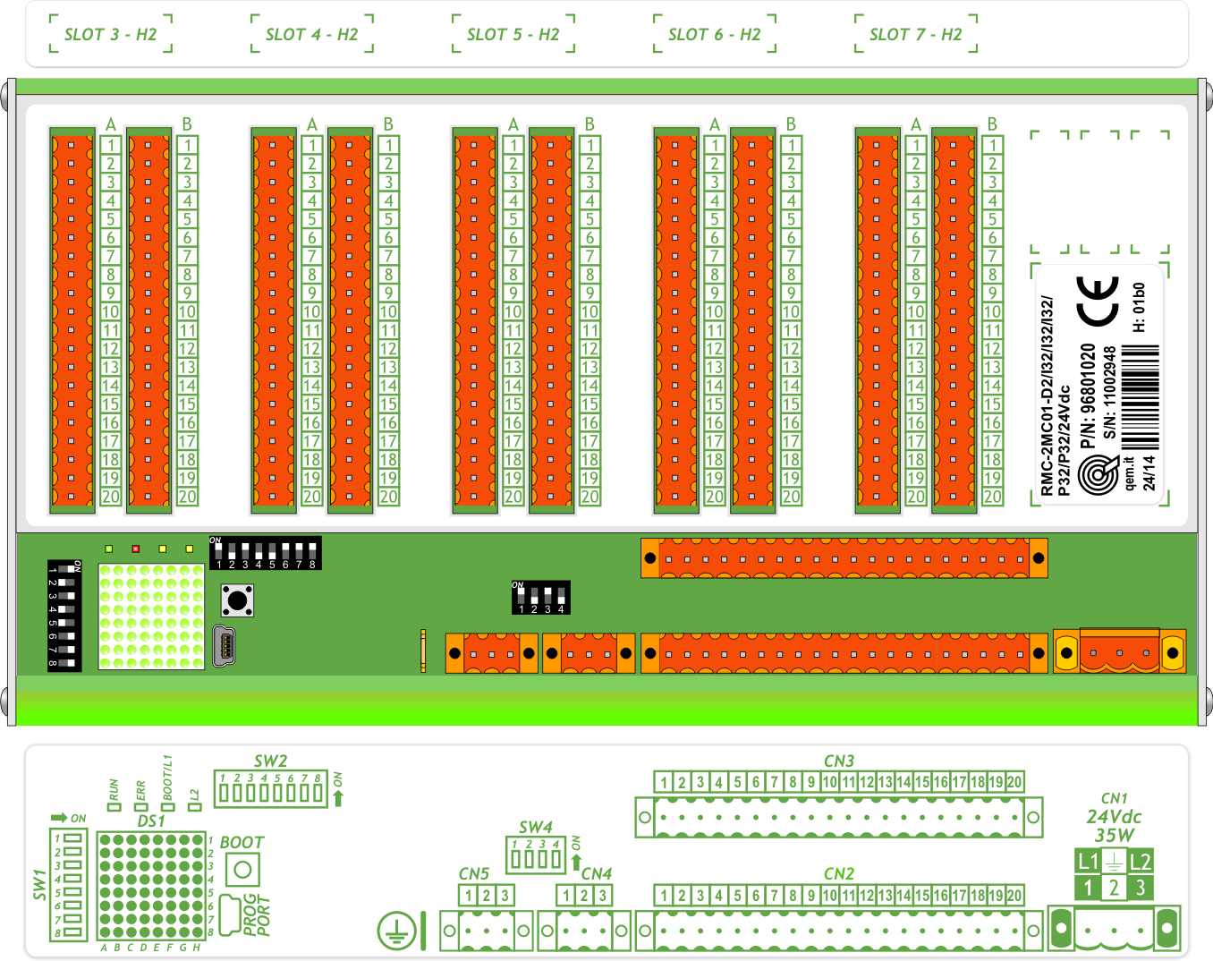
7.1 Slots
7.2 IMPOSTAZIONE DEI DIP-SWITCH
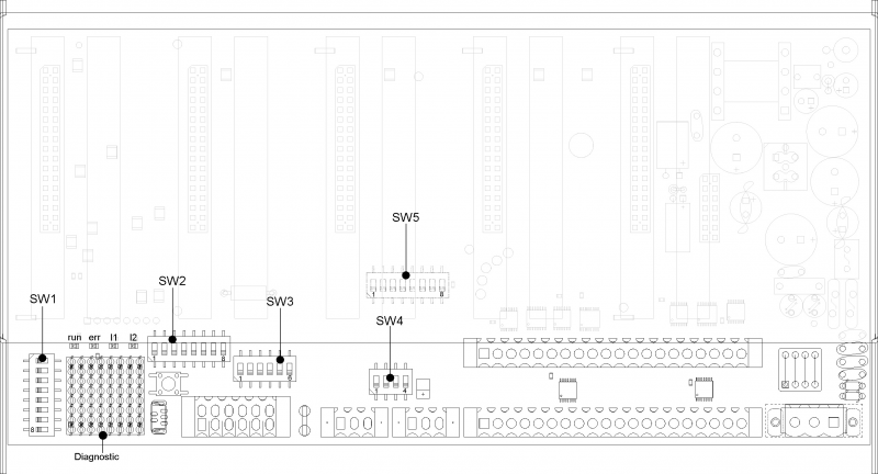
7.2.1 DIP-SWITCH SW1
Dip-switch di selezione velocità e indirizzo.
SW1 Dip Impostazione dei DIP Funzione 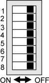
1 OFF ON OFF ON Selezione velocità
di CAN BUS2 OFF OFF ON ON 125 Kb/s 250 Kb/s 500 Kb/s 1 Mb/s 3 Impostazione indirizzo
slave (vedi tabella sottostante)4 5 6 7 8 Non utilizzabile Dip 3 Dip 4 Dip 5 Dip 6 Dip 7 Indirizzo slave OFF OFF OFF OFF OFF n.u. ON OFF OFF OFF OFF 1 OFF ON OFF OFF OFF 2 ON ON OFF OFF OFF 3 … … … … … … … … … … … … … … … … … … OFF ON ON ON ON 30 ON ON ON ON ON 31 7.2.2 DIP-SWITCH SW2
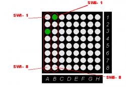
Il dip SW2 permette la selezione delle risorse che si vogliono controllare sui leds di diagnostica secondo la tabella sottostante
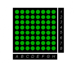
SW2 Dip 1 Dip 2 Dip 3 Dip4 Diagnostic type OFF OFF OFF OFF disable OFF OFF OFF OFF disable ON OFF OFF OFF system OFF ON OFF OFF Input 1-64 ON ON OFF OFF Input 65-128 OFF OFF ON OFF Output 1-64 ON OFF ON OFF Output 65-128 OFF ON ON OFF Analog input 1-8 ON ON ON OFF Analog input 9-16 OFF OFF OFF ON disable ON OFF OFF ON disable … … … … disable ON ON ON ON disable Ad esempio selezionando gli inputs da 1 a 64 avremo:
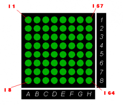
dove il leds acceso indica che l'ingresso è attivo.Per gli ingressi analogici (esclusi gli ingressi di misura della temperatura quali PT100 e termocoppie), invece, ogni colonna di leds rappresenta un Vmeter relativo ad un ingresso analogico.
Ad esempio selezionando gli analog inputs da 1 a 8 avremo:
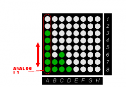
dove sulla colonna A sono accesi 6 leds, ad indicare che il valore dell'ingresso analogico è circa 6/8 del suo valore massimo( ad esempio per un ingresso analogico a 12 il valore sarà compreso tra 3072 e 3584).7.2.2.1 System diagnostic
Selezionando la diagnostica di sistema è possibile visualizzare lo stato dei dip-switch SW1 ed SW5:
7.2.3 DIP-SWITCH SW5
Il dip SW5 permette la selezione della gamma di schede installate.
Nome Gamma Dip 1 Dip 2 Dip 3 Dip 4 Dip 5 Dip 6 Dip 7 Dip 8 M1 OFF OFF OFF OFF OFF OFF OFF OFF M2 ON OFF OFF OFF OFF OFF OFF OFF D1 OFF ON OFF OFF OFF OFF OFF OFF D2 ON ON OFF OFF OFF OFF OFF OFF D3 OFF OFF ON OFF OFF OFF OFF OFF M3 ON OFF ON OFF OFF OFF OFF OFF G1 OFF ON ON OFF OFF OFF OFF OFF G2 ON ON ON OFF OFF OFF OFF OFF G3 OFF OFF OFF ON OFF OFF OFF OFF G4 ON OFF OFF ON OFF OFF OFF OFF G5 OFF ON OFF ON OFF OFF OFF OFF … … … … … … … … … … OFF ON ON ON ON ON ON ON … ON ON ON ON ON ON ON ON -
-


- Last modified: 2019/08/29 17:01