Tabela de conteúdos
MCE_P1R44F-009: Electrical Connections Manual
1. Informations
1.1 Release
| |
|||
| Document: | mce_p1r44f-009 | ||
|---|---|---|---|
| Description: | Electrical Connections Manual p1r44f-009 | ||
| Editor: | Andrea Zarantonello | ||
| Approver: | Giuliano Tognon | ||
| Link: | https://www.qem.eu/doku/doku.php/strumenti/qmoveplus/c1r44/p1r44f-001/mce_p1r44f-009 | ||
| Language: | English | ||
| Release document | Description | Note | Date |
| 01 | New manual | 25/11/2022 | |
1.2 Specifications
The copyright of this manual is reserved. No part of this document can be copied or reproduced in any form without the prior written permission of the QEM.
QEM has no assurances or guarantees on the content and specifically disclaims any liability inherent in the guarantees of eligibility for any particular purpose. The information in this document is subject to change without notice. QEM does not take any responsibility for any errors that may appear in this document.
Trademarks:
QEM® is a registered trademark.
2. Hardware and connections
The models of devices used for this application are:
-
C1-R44-FF30: CPU unit for motion control and automation logic;
-
A1-HMI-QC104-03/TP01/G16: operator terminal 10.4 “, touch screen, 256 colors;
-
RMC-3M B01 DD /I16/I16/I16/I16/0/24 Vdc: Multi-board remote I / O module;
-
RMC-3M C01 D5 /P16/P16/P16/P16/P16/24 Vdc: Multi-board remote I / O module;
2.1 C1-R44-FF30

| C1-R44 front view |

| Expansion 1MG2F |
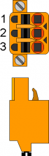
2.1.1 C1-R44: Power supply
2.1.1.1 C1-R44: CN1
The instrument must be powered at 24Vdc. Provide an external fuse in series with the + 24Volt positive conductor.
| CN1 | Terminal | Symbol | Description | |
|---|---|---|---|---|
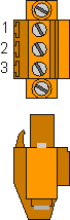 | 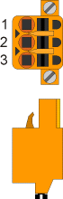 | 1 | | Positive power supply |
| 2 | GROUND | Ground-PE (signals) | ||
| 3 | | 0V power supply |
2.1.2 Connectivity
-
PROG PORT → Serial with TTL logic standard for programming.
-
USER PORT → Multistandard serial (RS232, RS422, RS485).
-
AUX RS485 PORT → Multistandard serial (RS232, RS422, RS485).
-
ETHERNET PORT → RJ45 connector
-
CAN PORT → “field bus” type Canbus.
2.1.2.1 ETHERNET port
| ETHERNET PORT | Description |
|---|---|
 | Connector RJ45. LED: * LINK: green led = cable connected (led on signals the cable is connected to both ends) * DATA: yellow led = data transmission (flashing led signals data transmission) |
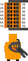
2.1.2.2 C1-R44: CN2 - PORTA USER
Serial port used to connect the A1-HMI-QC104 operator terminal. Set RS422 serial.
| CN2 | Pin | RS485 | RS232 | RS422 | PE |
|---|---|---|---|---|---|
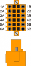 | 1A | Canal A | |||
| 2A | Canal B | ||||
| 3A | Common 0 Volt | ||||
| 4A | Common 0 Volt | ||||
| 5A | TX | ||||
| 6A | PE | ||||
| 1B | RX (+) | ||||
| 2B | RXN (-) | ||||
| 3B | TX (+) | ||||
| 4B | TXN (-) | ||||
| 5B | RX | ||||
| 6B | PE |
Connection example:


2.1.2.3 USER PORT electrical standard setting
Attention: Select the electrical standard RS422.

2.1.2.4 PROG PORT and USER PORT baud-rate selector
SET PROG PORT 115200
SET USER PORT 57600
| SW 1 | Dip | DIP setting | Function | |||
|---|---|---|---|---|---|---|
 | 1 | OFF | Baud rate 57600 | Transmission speed selection PROG PORT | ||
| ON | Baud rate 115200 | |||||
| 2 | OFF | Baud rate 57600 | Baud rate selection USER PORT | |||
| ON | Baud rate 115200 | |||||
| 3 | OFF | Can also be used by SERCOM and MODBUS | devices Operating mode selection PROG PORT | |||
| ON | Not usable by SERCOM and MODBUS devices | |||||
| 4 | OFF | ON | OFF | ON | CANbus baud rate (CanOpen) | |
| 5 | OFF | OFF | ON | ON | ||
| Baud rate 125KB/S | Baud rate 250KB/S | Baud rate 500KB/S | Baud rate 1MB/S |
|||
| 6 | OFF | MMC/SD | External media device selection in system functions | |||
| ON | USB | |||||
| 7 | Reserved for internal use. Leave OFF | |||||
| 8 | OFF | PROG PORT normal | Select the USER PORT as PROG PORT | |||
| ON | PROG PORT on the USER PORT connector | |||||
2.1.2.5 C1-R44: CN5 - CAN PORT
| CN5 | Terminal | Symbol | Description |
|---|---|---|---|
 | 1 | 0V | Common CAN |
| 2 | CAN L | Terminal CAN L | |
| 3 | CAN H | Terminal CAN H |
2.1.2.6 Termination resistors setting
| Name jumper | Setting | Function | |
|---|---|---|---|
JP3 JP4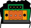 | JP3 | INSERTED | CAN termination activated |
| JP4 |
2.1.2.7 CAN cable connection example
There are two ways of connecting:
1st way:

2nd way:

2.1.3 Digital Input
| S = State | A = Action | ID |
|---|---|---|
| NO = Normally Open | I = Impulsive | ID = Software |
| NC = Normally Closed | C = Continuous |
2.1.3.1 C1-R44: CN7
| CN 7 | Pin | ID | Description | S | A | |
|---|---|---|---|---|---|---|
 | 1 | 0V | 0 Volt ( common inputs I1 ÷ I8 ) | |||
| 2 | I1 | Thermal heads | - | NC | C | |
| 3 | I2 | Bridge fault | - | |||
| 4 | I3 | Conveyor belt fault | - | NO | I | |
| 5 | I4 | Roller conveyor fault | - | |||
| 6 | I5 | Air pressure | - | NC | C | |
| 7 | I6 | Water pressure | - | |||
| 8 | I7 | Forward bridge sensor | - | |||
| 9 | I8 | Back bridge sensor | - | |||
2.1.3.1.1 Example of connection

2.1.3.2 C1-R44: CN6
| CN 6 | Pin | ID | Description | S | A | |
|---|---|---|---|---|---|---|
| | 1 | 0V | 0 Volt ( common inputs I9 ÷ I16 ) | |||
| 2 | I9 | Bridge zero sensor | - | NO | I | |
| 3 | I10 | Slab presence sensor | End of roller conveyor | |||
| 4 | I11 | Start conveyor belt | ||||
| 5 | I12 | Abrasive sensor worn | - | |||
| 6 | I13 | Emergency | - | NC | C | |
| 7 | I14 | Pressure lubrication circuit feedback | - | |||
| 8 | I15 | n.u. | Free | |||
| 9 | I16 | n.u. | Free | |||
2.1.3.2.1 Example of connection

2.1.3.3 C1-R44: CN18
Duplication of QC104 inputs if necessary
| CN 18 | Pin | ID | Descrizione | S | A | |
|---|---|---|---|---|---|---|
| | 1 | 0V | 0 Volt ( common inputs I9 ÷ I16 ) | |||
| 2 | n.u | n.u | ||||
| 3 | I18 | Jog Bridge | Forward | NO | I | |
| 4 | I19 | Backward | ||||
| 5 | I20 | START | ||||
| 6 | I21 | STOP | ||||
| 7 | I22 | Abrasive changing button | ||||
| 8 | I23 | MAN/AUTO | ||||
| 9 | I24 | STAND-BY | ||||
2.1.4 Digital output
| S = State | ID |
|---|---|
| OFF | ID = Software |
| ON |
2.1.4.1 C1-R44: CN9
| CN 9 | Pin | ID | Description | S | |
|---|---|---|---|---|---|
 | 1 | V+ | + 24 Volt (common outputs 01 ÷ 04) | ||
| 2 | O1 | ON/OFF Bridge | - | OFF | |
| 3 | O2 | ON/OFF Conveyor belt | - | ||
| 4 | O3 | ON/OFF Roller conveyor | - | ||
| 5 | O4 | Up / Down Brush | - | ||
| 6 | V+ | +24 Volt (common outputs 05 ÷ 08 ) | |||
| 7 | O5 | ON/OFF Previous Machine | - | OFF | |
| 8 | O6 | Lubrication | - | ||
| 9 | O7 | Stop Conveyor belt | - | ||
| 10 | O8 | Alarm state | - | ON | |
| 11 | 0V | 0 Volt (common outputs 01 ÷ 08) | |||
2.1.4.1.1 Example of connection

Duplication of outputs (to facilitate wiring)
Some outputs of QC104 and RMC-3M B01 DD module are duplicated on C1-R44-FF30:
2.1.4.2 C1-R44: CN8 (Out +24 Volt, 500mA)
| CN 8 | Pin | ID | Description | Head | S |
|---|---|---|---|---|---|
| | 1 | V+ | +24 Volt (common outputs O25÷O34) | ||
| 2 | O17 | AUTO LAMP ON | OFF | ||
| 3 | O18 | ALARM LAMP | |||
| 4 | O25 | ON/OFF | 1 | ||
| 5 | O28 | 2 | |||
| 6 | V+ | +24 Volt (common outputs O37÷O46) | |||
| 7 | O31 | ON/OFF | 3 | OFF | |
| 8 | O34 | 4 | |||
| 9 | O37 | 5 | |||
| 10 | O40 | 6 | |||
| 11 | 0V | 0 Volt (common outputs O25÷O46) |
2.1.4.3 C1-R44: CN 25 (Out +24 Volt, 500 mA)
Engine starter duplication
| CN 25 | Pin | ID | Description | Head | S |
|---|---|---|---|---|---|
| | 1 | V+ | +24 Volt (common outputs O49÷O58) | ||
| 2 | O43 | ON/OFF | 7 | OFF | |
| 3 | O46 | 8 | |||
| 4 | O49 | 9 | |||
| 5 | O52 | 10 | |||
| 6 | V+ | +24 Volt (common outputs O61÷O70) | |||
| 7 | O55 | ON/OFF | 11 | OFF | |
| 8 | O58 | 12 | |||
| 9 | O61 | 13 | |||
| 10 | O64 | 14 | |||
| 11 | 0V | 0 Volt (common outputs O49÷O70) |
2.1.4.4 C1-R44: CN 20 (Out +24 Volt, 500 mA)
Engine starter duplication
| CN 20 | Pin | ID | Description | Head | S |
|---|---|---|---|---|---|
| | 1 | V+ | +24 Volt (common outputs O73÷O82) | ||
| 2 | O67 | ON/OFF | 15 | OFF | |
| 3 | O70 | 16 | |||
| 4 | O73 | 17 | |||
| 5 | O76 | 18 | |||
| 6 | V+ | +24 Volt (common outputs O85÷O88) | |||
| 7 | O79 | ON/OFF | 19 | OFF | |
| 8 | O82 | 20 | |||
| 9 | O85 | 21 | |||
| 10 | O88 | 22 | |||
| 11 | 0V | 0 Volt (common outputs O73÷O18) |
2.1.5 Bidirectional counting inputs
2.1.5.1 Encoder Push Pull
2.1.5.1.1 C1-R44: CN14
| CN 14 (Push Pull) | PIN | ID | DESCRIPTION | COMMENTS | ||
|---|---|---|---|---|---|---|
 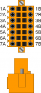 | 1B | +24V IN | Input +24 Volts | Bridge Count | ||
| 1A | +24V OUT | Output +24 Volts | Encoder power supply | |||
| 2A | PHA1 | Phase A | - | |||
| 3A | PHB1 | Phase B | - | |||
| 4A | - | - | - | |||
| 5A | 0V ∩ | Connect to PIN 5B | Common of counting inputs. Internally connected to 0Volt (PIN 3 - CN1) |
|||
| 6A | 0V ∩ | Connect to PIN 6B | ||||
| 7A | 0V ∩ | Connect to PIN 7B | ||||
2.1.5.1.2 Connection example

2.1.5.1.3 C1-R44: CN15
| CN15 (Push Pull) | PIN | ID | DESCRIPTION | COMMENTS | ||
|---|---|---|---|---|---|---|
| | 1B | +24V IN | Input +24 Volts | Belt Count | - | |
| 1A | +24V OUT | Output +24 Volts | Encoder power supply | |||
| 2A | PHA2 | Phase A | - | |||
| 3A | PHB2 | Phase B | - | |||
| 4A | - | - | - | |||
| 5A | 0V ∩ | Connect to PIN 5B | Common of counting inputs. Internally connected to 0Volt (PIN 3 - CN1) |
|||
| 6A | 0V ∩ | Connect to PIN 6B | ||||
| 7A | 0V ∩ | Connect to PIN 7B | ||||
2.1.5.1.4 Connection example

2.1.5.2 Encoder Line Driver 24 Volt
2.1.5.2.1 C1R44: CN14
| CN 14 (Line Driver 24 Volt) | PIN | ID | DESCRIPTION | |||
|---|---|---|---|---|---|---|
| | 1B | +24V IN | Input +24 Volts | Bridge Count | ||
| 1A | +24V OUT | Encoder power supply | ||||
| 2A | PHA1 | Phase A+ | ||||
| 3A | PHB1 | Phase B+ | ||||
| 4A | - | - | ||||
| 5B | PHA1- | Phase A- | ||||
| 6B | PHB1- | Phase B- | ||||
| 7B | - | - | ||||
2.1.5.2.2 Connection example

2.1.5.2.3 C1R44: CN15
| CN15 (24 Volt Line Driver) | PIN | ID | DESCRIPTION | |||
|---|---|---|---|---|---|---|
| | 1B | +24V IN | Input +24 Volts | Belt Count | ||
| 1A | +24V OUT | Encoder power supply | ||||
| 2A | PHA2 | Phase A+ | ||||
| 3A | PHB2 | Phase B+ | ||||
| 4A | - | - | ||||
| 5B | PHA2- | Phase A- | ||||
| 6B | PHB2- | Phase B- | ||||
| 7B | - | - | ||||
2.1.5.2.4 Connection example

2.1.5.3 5 Volt simulated line driver encoder
2.1.5.3.1 C1R44: CN14
| CN 14 (5 Volt Simulated Line Driver) | PIN | ID | DESCRIPTION | |||
|---|---|---|---|---|---|---|
| | 2B | PHA1+ | Phase A+ | Bridge Count | ||
| 3B | PHB1+ | Phase B+ | ||||
| 4B | - | - | ||||
| 5B | PHA1- | Phase A- | ||||
| 6B | PHB1- | Phase B- | ||||
| 7B | - | - | ||||
2.1.5.3.2 Connection example

2.1.5.3.3 C1R44: CN15
| CN15 (5 Volt Simulated Line Driver) | PIN | ID | DESCRIPTION | |||
|---|---|---|---|---|---|---|
| | 2B | PHA2+ | Phase A+ | Belt Count | ||
| 3B | PHB2+ | Phase B+ | ||||
| 4B | - | - | ||||
| 5B | PHA2- | Phase A- | ||||
| 6B | PHB2- | Phase B- | ||||
| 7B | - | - | ||||
2.1.5.3.4 Connection example

2.1.6 Analog outputs
2.1.6.1 C1-R44: CN12
| CN 12 | Pin | ID | Description |
|---|---|---|---|
 | 1 | GA01 | Common analog output AO1÷AO2 |
| 2 | AO1 | Bridge command: +/- 0÷10 V | |
| 3 | AO2 | Belt command: 0/10 V | |
| 4 | GA02 | Common analog output AO3÷AO4 | |
| 5 | AO3 | n.u. | |
| 6 | AO4 | n.u. |
2.1.6.1.1 Connection example

2.2 A1-HMI-QC104
 |
| Front view |
 |
| Rear view |
2.2.1 A1-HMI-QC104: Power supply
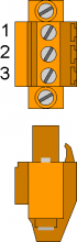
2.2.1.1 A1-HMI-QC104: CN 1
The instrument must be powered at 24Vdc. Provide an external fuse in series with the + 24Volt positive conductor.
| CN1 | Terminal | Symbol | Description | |
|---|---|---|---|---|
| | | 1 | | Positive power supply |
| 2 | GROUND | Ground-PE (signals) | ||
| 3 | | 0V power supply | ||
2.2.2 Connectivity
2.2.2.1 A1-HMI-QC104: CN2 - USER PORT
Serial port used to connect the A1-HMI-QC104 operator terminal to the C1-R44-FC30 controller. Use the RS422 serial.
| CN2 | Pin | RS485 | RS232 | RS422 | PE |
|---|---|---|---|---|---|
| | 1A | Channel A | |||
| 2A | Channel B | ||||
| 3A | Common 0 Volts | ||||
| 4A | Common 0 Volts | ||||
| 5A | TX | ||||
| 6A | PE | ||||
| 1B | RX (+) | ||||
| 2B | RXN (-) | ||||
| 3B | TX (+) | ||||
| 4B | TXN (-) | ||||
| 5B | RX | ||||
| 6B | PE |
Connection example:
2.2.2.1.1 USER PORT electrical standard setting
N.B. Select the RS422 electrical standard.
2.2.2.2 PROG PORT and USER PORT baud-rate selector
SET PROG PORT 115200
SET USER PORT 57600
| SW 1 | Dip | DIP setting | Function | |||
|---|---|---|---|---|---|---|
 | 1 | OFF | OFF | ON | ON | Transmission speed selection PROG PORT |
| 2 | OFF Baud rate 38400 | ON Baud rate 115200 | OFF Baud rate 19200 | ON Baud rate 57600 |
||
| 3 | OFF | OFF | ON | ON | Baud rate selection USER PORT | |
| 4 | OFF Baud rate 38400 | ON Baud rate 115200 | OFF Baud rate 19200 | ON Baud rate 57600 |
||
| 5 | Unused |
|||||
| 6 | ||||||
| 7 | ||||||
| 8 | OFF | ON | Select the USER PORT as PROG PORT | |||
| PROG PORT normal | PROG PORT to the USER PORT connector | |||||
2.2.3 Digital input
| S = State | A = Action | ID |
|---|---|---|
| NO = Normally open | I = Impulsive | ID = Software |
| NC = Normally closed | C = Continuous |
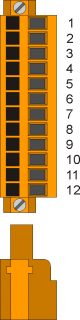
2.2.3.1 A1-HMI-QC104: CN11
| CN 11 | Pin | ID | Description | S | A | |
|---|---|---|---|---|---|---|
 | 1 | - | Not used | |||
| 2 | - | Not used | ||||
| 3 | 0V | 0 Volt (Commmon digital input I17÷I24) | ||||
| 4 | I17 | Not used | ||||
| 5 | I18 | Jog Bridge | Next | NO | I |
|
| 6 | I19 | Back | ||||
| 7 | I20 | START | - | |||
| 8 | I21 | STOP | - | |||
| 9 | I22 | Abrasive change | - | |||
| 10 | I23 | MAN / AUTO | - | |||
| 11 | I24 | STAND-BY | - | |||
| 12 | 0V | 0 Volt (Commmon digital input I17÷I24) | ||||
2.2.3.1.1 Connection example

2.2.3.2 A1-HMI-QC104: CN12
All inputs of these terminals are marked as n.u. (not used)
| CN12 | Terminal | Symbol | Description | Address |
|---|---|---|---|---|
 | 1 | - | n.u. |
|
| 2 | - | |||
| 3 | - | |||
| 4 | - | |||
| 5 | - | |||
| 6 | - | |||
| 7 | - | |||
| 8 | - | |||
| 9 | - | |||
| 10 | - | |||
| 11 | - | |||
| 12 | - | |||
2.2.4 Digital outputs
| S = State | ID |
|---|---|
| OFF | ID = Software |
| ON |
2.2.4.1 A1-HMI-QC104: CN15
| Pin | ID | Description | S | ||
|---|---|---|---|---|---|
 | 1 | V+ | + 24 Volt (common outputs 01 ÷ 04) | ||
| 2 | O1 | Lamp | AUTOMATIC ON | OFF | |
| 3 | O2 | ALARM | |||
| 4 | - | n.u. | |||
| 5 | O3 | Lamp | PRE-START | OFF | |
| 6 | O4 | RUN | |||
| 7 | 0V | 0 Volt (common outputs 01 ÷ 08) | |||
| 8 | O5 | n.u. | |||
| 9 | O6 | ||||
| 10 | O7 | ||||
| 11 | O8 | ||||
2.2.4.1.1 Connection example

2.3 RMC-3M-DD
This module has to be placed near the sensor bar, so the wiring is easier.
 |
| General view |
 |
| Bus composition |
2.3.1 RMC-3M-DD: CN1 - Power supply
| CN 1 | Terminal | Symbol | Description | |
|---|---|---|---|---|
 |  | 1 | | 0V power supply |
| 2 | TERRA | Ground-PE (signals) | ||
| 3 | | Positive power supply | ||
2.3.2 Connectivity
2.3.2.1 RMC-3M-DD: CN2 - CN3 - CAN PORT
 | 1 | 0 Volt - Common CanOpen Port |
| 2 | CAN L | |
| 3 | CAN H |
2.3.2.1.1 Example of cable connection

2.3.2.2 Switch 1
| SW1 | DIP No. | Set | Function |
|---|---|---|---|
 | 1 | OFF | DIP 1-2: Transmission speed (500 Kbit/s ) |
| 2 | ON | ||
| 3 | ON | DIP 3-8: Module address (address 1) |
|
| 4 | OFF | ||
| 5 | OFF | ||
| 6 | OFF | ||
| 7 | OFF | ||
| 8 | OFF |
2.3.2.3 Switch 3
Check CAN connection to determine the activation of the termination resistor
| SW3 | Num. Dip | Name Dip | DIP setting | Function |
|---|---|---|---|---|
 | 1 | JP1 | ON | Termination CAN PORT |
| 2 | JP2 | ON | ||
| 3 | ||||
| 4 |
2.3.3 RMC-3M-DD: Digital Outputs
2.3.4 SLOT 3 (H1-P16 : Out +24 Volt, 500 mA)
| n.Out | Head | Description | Pin | Connector SLOT 3 | Pin | n.Out | Head | Description |
|---|---|---|---|---|---|---|---|---|
| 25 | 1 | ON | 1A | 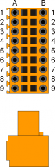 | 1B | 33 | 3 | Down |
| 26 | 1 | Up | 2A | 2B | 34 | 4 | ON | |
| 27 | 1 | Down | 3A | 3B | 35 | 4 | Up | |
| 28 | 2 | ON | 4A | 4B | 36 | 4 | Down | |
| 29 | 2 | Up | 5A | 5B | 37 | 5 | ON | |
| 30 | 2 | Down | 6A | 6B | 38 | 5 | Up | |
| 31 | 3 | ON | 7A | 7B | 39 | 5 | Down | |
| 32 | 3 | Up | 8A | 8B | 40 | 6 | ON | |
| V+ | +24 Volt | 9A | 9B | V+ | +24 Volt |
2.3.5 SLOT 4 (H1-P16 : Out +24 Volt, 500 mA)
| n.Out | Head | Description | Pin | Connector SLOT 4 | Pin | n.Out | Head | Description |
|---|---|---|---|---|---|---|---|---|
| 41 | 6 | Up | 1A | | 1B | 49 | 9 | ON |
| 42 | 6 | Down | 2A | 2B | 50 | 9 | Up | |
| 43 | 7 | ON | 3A | 3B | 51 | 9 | Down | |
| 44 | 7 | Up | 4A | 4B | 52 | 10 | ON | |
| 45 | 7 | Down | 5A | 5B | 53 | 10 | Up | |
| 46 | 8 | ON | 6A | 6B | 54 | 10 | Down | |
| 47 | 8 | Up | 7A | 7B | 55 | 11 | ON | |
| 48 | 8 | Down | 8A | 8B | 56 | 11 | Up | |
| V+ | +24 Volt | 9A | 9B | V+ | +24 Volt |
2.3.6 SLOT 5 (H1-P16 : Out +24 Volt, 500 mA)
| n.Out | Head | Description | Pin | Connector SLOT 5 | Pin | n.Out | Head | Description |
|---|---|---|---|---|---|---|---|---|
| 57 | 11 | Down | 1A | | 1B | 65 | 14 | Up |
| 58 | 12 | ON | 2A | 2B | 66 | 14 | Down | |
| 59 | 12 | Up | 3A | 3B | 67 | 15 | ON | |
| 60 | 12 | Down | 4A | 4B | 68 | 15 | Up | |
| 61 | 13 | ON | 5A | 5B | 69 | 15 | Down | |
| 62 | 13 | Up | 6A | 6B | 70 | 16 | ON | |
| 63 | 13 | Down | 7A | 7B | 71 | 16 | Up | |
| 64 | 14 | ON | 8A | 8B | 72 | 16 | Down | |
| V+ | +24 Volt | 9A | 9B | V+ | +24 Volt |
2.3.7 SLOT 6 (H1-P16 : Out +24 Volt, 500 mA)
| n.Out | Head | Description | Pin | Connector SLOT 6 | Pin | n.Out | Head | Description |
|---|---|---|---|---|---|---|---|---|
| 73 | 17 | ON | 1A | | 1B | 81 | 19 | Down |
| 74 | 17 | Up | 2A | 2B | 82 | 20 | ON | |
| 75 | 17 | Down | 3A | 3B | 83 | 20 | Up | |
| 76 | 18 | ON | 4A | 4B | 84 | 20 | Down | |
| 77 | 18 | Up | 5A | 5B | 85 | 21 | ON | |
| 78 | 18 | Down | 6A | 6B | 86 | 21 | Up | |
| 79 | 19 | ON | 7A | 7B | 87 | 21 | Down | |
| 80 | 19 | Up | 8A | 8B | 88 | 22 | ON | |
| V+ | +24 Volt | 9A | 9B | V+ | +24 Volt |
2.3.8 SLOT 7 (H1-P16 : Out +24 Volt, 500 mA)
| n.Out | Head | Description | Pin | Connector SLOT 7 | Pin | n.Out | Description |
|---|---|---|---|---|---|---|---|
| 89 | 22 | Up | 1A | | 1B | 97 | reserve |
| 90 | 22 | Down | 2A | 2B | 98 | reserve | |
| 91 | reserve | 3A | 3B | 99 | reserve | ||
| 92 | reserve | 4A | 4B | 100 | reserve | ||
| 93 | reserve | 5A | 5B | 101 | reserve | ||
| 94 | reserve | 6A | 6B | 102 | reserve | ||
| 95 | reserve | 7A | 7B | 103 | reserve | ||
| 96 | reserve | 8A | 8B | 104 | reserve | ||
| V+ | +24 Volt | 9A | 9B | V+ | +24 Volt |
2.4 RMC-3M-D5
| |
| General view |
|
| Bus composition |
2.4.1 RMC-3M-D5: CN1- Power supply (Power Input - 24 Vdc)
| CN 1 | Terminal | Symbol | Description | |
|---|---|---|---|---|
| | | 1 | | 0V power supply |
| 2 | GROUND | Ground-PE (segnali) | ||
| 3 | | Positive power supply |
2.4.2 RMC-3M-D5: CN2 - CN3 - CAN PORT
| | 1 | 0 Volt - Common CanOpen Port |
| 2 | CAN L | |
| 3 | CAN H |
2.4.2.0.1 Example of cable connection
2.4.2.1 Switch 1
| SW1 | DIP No. | Set | Function |
|---|---|---|---|
 | 1 | OFF | DIP 1-2: Transmission speed (500 Kbit/s ) |
| 2 | ON | ||
| 3 | OFF | DIP 3-8: Module address (address 2) |
|
| 4 | ON | ||
| 5 | OFF | ||
| 6 | OFF | ||
| 7 | OFF | ||
| 8 | OFF |
2.4.2.2 Switch 3
Check CAN connection to determine the activation of the termination resistor
| SW3 | Num. Dip | Name Dip | DIP setting | Function |
|---|---|---|---|---|
| | 1 | JP1 | ON | Termination CAN PORT |
| 2 | JP2 | ON | ||
| 3 | ||||
| 4 |
2.4.3 RMC-3M-D5: Digital inputs
2.4.4 SLOT 3 (H1- I1÷16)
| n.In | Sensor | Description | Pin | Connector SLOT 3 | Pin | Description | Sensor | n.In |
|---|---|---|---|---|---|---|---|---|
| +24V | Out 24 Volt | 1A | | 1B | Common 0Vdc | 0V | ||
| 33 | 1 | 2A | 2B | 9 | 41 | |||
| 34 | 2 | 3A | 3B | 10 | 42 | |||
| 35 | 3 | 4A | 4B | 11 | 43 | |||
| 36 | 4 | 5A | 5B | 12 | 44 | |||
| 37 | 5 | 6A | 6B | 13 | 45 | |||
| 38 | 6 | 7A | 7B | 14 | 46 | |||
| 39 | 7 | 8A | 8B | 15 | 47 | |||
| 40 | 8 | 9A | 9B | 16 | 48 |
2.4.5 SLOT 4 (H1- I17÷32)
| n.In | Sensor | Description | Pin | Connettore SLOT 4 | Pin | Description | Sensor | n.In |
|---|---|---|---|---|---|---|---|---|
| +24V | Out 24 Volt | 1A | | 1B | Common 0Vdc | 0V | ||
| 49 | 17 | 2A | 2B | 25 | 57 | |||
| 50 | 18 | 3A | 3B | 26 | 58 | |||
| 51 | 19 | 4A | 4B | 27 | 59 | |||
| 52 | 20 | 5A | 5B | 28 | 60 | |||
| 53 | 21 | 6A | 6B | 29 | 61 | |||
| 54 | 22 | 7A | 7B | 30 | 62 | |||
| 55 | 23 | 8A | 8B | 31 | 63 | |||
| 56 | 24 | 9A | 9B | 32 | 64 |
2.4.6 SLOT 5 (H1- I33÷48)
| n.In | Sensor | Description | Pin | Connettore SLOT 5 | Pin | Description | Sensor | n.In |
|---|---|---|---|---|---|---|---|---|
| +24V | Out 24 Volt | 1A | | 1B | Common 0Vdc | 0V | ||
| 65 | 33 | 2A | 2B | 41 | 73 | |||
| 66 | 34 | 3A | 3B | 42 | 74 | |||
| 67 | 35 | 4A | 4B | 43 | 75 | |||
| 68 | 36 | 5A | 5B | 44 | 76 | |||
| 69 | 37 | 6A | 6B | 45 | 77 | |||
| 70 | 38 | 7A | 7B | 46 | 78 | |||
| 71 | 39 | 8A | 8B | 47 | 79 | |||
| 72 | 40 | 9A | 9B | 48 | 80 |
2.4.7 SLOT 6 (H1- I49÷64)
| n.In | Sensor | Description | Pin | Connettore SLOT 7 | Pin | Description | Sensor | n.In |
|---|---|---|---|---|---|---|---|---|
| +24V | Out 24 Volt | 1A | | 1B | Common 0Vdc | 0V | ||
| 81 | 49 | 2A | 2B | 57 | 89 | |||
| 82 | 50 | 3A | 3B | 58 | 90 | |||
| 83 | 51 | 4A | 4B | 59 | 91 | |||
| 84 | 52 | 5A | 5B | 60 | 92 | |||
| 85 | 53 | 6A | 6B | 61 | 93 | |||
| 86 | 54 | 7A | 7B | 62 | 94 | |||
| 87 | 55 | 8A | 8B | 63 | 95 | |||
| 88 | 56 | 9A | 9B | 64 | 96 |
3. Support
Request for assistance
In order to be able to provide you a quick service, at the minimum cost, we need your help.
 | 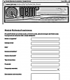 |
| Follow all the instructions provided in the manual MIMAT | If the problem persists, fill in the “Assistance request form” on the page Contacts of the site www.qem.it. Our technicians will obtain essential elements for understanding your problem. |
Repair
In order to provide you with an efficient service, please read and follow the instructions here reported
Shipping
It is recommended to pack the instrument with materials that can absorb any falls.
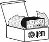 |  |  |
| Use the original packaging: it must protect the instrument during transport. | Attach: 1. A description of the anomaly; 2. Part of the wiring diagram where the instrument is inserted 3. Programming the instrument ( set up, work quotas, parameters …). | A thorough description of the problem will allow us to quickly identify and resolve your problem. Careful packaging will avoid further inconveniences. |