Indice
MDI_P1R44F-024: Installer Manual
1. Information
1.1 Release
| |
|||
| Document: | mdi_p1r44f-024 | ||
|---|---|---|---|
| Description: | Installation Manual p1r44f-024 | ||
| Editor: | Andrea Zarantonello | ||
| Approver: | Giuliano Tognon | ||
| Link: | https://www.qem.eu/doku/doku.php/strumenti/qmoveplus/c1r44/p1r44f-024/mdi_p1r44f-024 | ||
| Language: | English | ||
| Document Release | Description | Notes | Date |
| 01 | New manual | 12/22/2023 | |
Specifications
The copyright of this manual is reserved. No part of this document may be copied or reproduced in any form without the prior written permission of QEM.
QEM makes no representations or warranties regarding the contents and specifically disclaims any liability for fitness for any particular purpose. The information in this document is subject to change without notice. QEM assumes no responsibility for any errors that may appear in this document.
Registered Trademarks:
-
QEM® is a registered trademark.
2. Setup
2.1 Machine Overview
Machine top view:

| n: | Description: |
|---|---|
| 1 | Raw Slab |
| 2 | Conveyor Belt Encoder |
| 3 | Limit Switch Bar |
| 4 | Conveyor Belt direction |
| 5 | Moving Bridge |
| 6 | Polishing Heads |
| 7 | Infeed Roller |
2.2 Access to Setup
Access to the setup can be done from the MENU page by entering the password 035.

 →
→ 
 →
→ 
There is a dedicated setup for the correction of the head up/down movement, accessible by entering the password 123.
 →
→ 
2.2.1 Introduction to SETUP
List of parameters divided into
 | general parameters |
 | parameters associated with the heads |
 | parameters associated with the bridge |
 | parameters associated with the sensor bar |
 | parameters associated with the conveyor belt |
 | parameters associated with the head up/down valves |
2.3 Generic Setup

| Parameter Name | Unit of Measurement | Default | Range | Description |
|---|---|---|---|---|
| PG01 : LANGUAGE | - | ITA | 1 ÷ 2 | 1: ITALIAN 2: ENGLISH |
| PG02 : MAX CORRECTIONS | mm | 0 | 0-9999 | Maximum correction applicable for head up and down movement |
| PG03 : DECIMAL POINT | - | 1 | 0 ÷ 3 | It is the position of the decimal point in the display of measurements. |
| PG04 : PARTIAL LIFT TIMOUT | s | 0 | 99.9 | Timer after which the heads lift from a partial up movement. |
| PG05 : HORIZONTAL STEP | mm | 50.0 | - | Distance between the limit switches on the sensor bar. Allows detecting the shape of the slab. |
| PG06 : ORTHOGONAL STEP | mm | 50.0 | - | Space determined by the encoder. Allows detecting the shape of the slab. |
| PG07 : ENABLE BRIDGE SLAVE | - | OFF | ON - OFF | Enable/Disable slave bridge swing motor. Enable only if a second motor is used for bridge movement |
| PG08 : LINE MEASURE | mm | 1 | 0 ÷ 999999 | Indicates the distance, in measurement units, traveled by the conveyor belt to obtain the encoder pulses set in the pulse parameter. |
| PG09 : LINE PULSE | - | 1 | 0 ÷ 999999 | Indicates the pulses multiplied by 4 provided by the conveyor belt encoder to obtain the space set in the measure parameter. The ratio between measure and pulse is the encoder resolution and must have values between 1 and 0.000935. |
| PG10: SLAB ENTRY | - | LFT | LFT - RT | Indicates the slab entry position: LFT = slab enters the machine from the left RT = slab enters the machine from the right |
| PG11 : BRIDGE AUTO-LEARN | - | OFF | 0 ÷ 1 | Enables the option to automatically learn the minimum and maximum slab height to optimize bridge swing. |
| PG12 : ENABLE ABRASIVE MANAGEMENT | - | OFF | ON-OFF | Enables the reading of abrasive thickness and head height. Enable only if analog inputs are used for abrasive thickness measurement |
| PG14 : HEADS ENABLE/DISABLE | - | TOUCH | TOUCH - SELECTORS | Mode of enabling/disabling heads: TOUCH = enable/disable heads via touchscreen SELECTORS = enable/disable heads via selectors |
| PG15 : AUTO/MANUAL SELECTOR | - | ON | 0 ÷ 1 | Enables manual/auto selector. |
| PG16 : PRESTART TIME | s | 3.0 | 0 ÷ 9999.9 | Time between start command and actual machine start (during this time, the warning signal is active). If less than the motor activation time, the greater of the two is applied. |
| PG17 : LUBRICATION TIME ON | s | 0.0 | 0 ÷ 9999.9 | Lubrication ON time. |
| PG18 : LUBRICATION TIME OFF | s | 0.0 | 0 ÷ 9999.9 | Lubrication OFF time. |
| PG19 : MOTORS TIME ON | s | 1.000 | 0 ÷ 99.999 | Pause time between the activation of one motor and the next (in sequential activation). |
| PG20 : MOTORS TIME OFF | s | 0.200 | 0 ÷ 99.999 | Pause time between the deactivation of one motor and the next (in sequential deactivation). |
| PG21 : BELT EXIT MOTOR TIME | s | 0.000 | 0 ÷ 99.999 | Wait time to start sequential motor deactivation, starting when there are no more pieces on the conveyor belt. |
| PG22 : ABRASIVE THICKNESS WARNING | mm | 300 | 0 ÷ 999999 | Minimum abrasive thickness measurement. If the abrasive thickness is less than or equal to the set value, a warning is displayed. |
| PG23 : ABRASIVE THICKNESS ALARM | mm | 200 | 0 ÷ 999999 | Minimum abrasive thickness measurement. If the abrasive thickness is less than or equal to the set value, an alarm is displayed. |
| PG24 : ABRASIVE ALARM TIMEOUT | ms | 0 | 0 ÷ 999999 | Timer for which if the abrasive thickness is below the warning or alarm value for the set time, the respective message appears. |
| PG25 : HEADS OUTPUT | - | CONST | CONST ÷ PULSE | Operating mode of the heads activation output. CONST = the output remains active for the entire head usage time, PULSE = the output remains active for a set time (PG27). |
| PG26 : BELT OUTPUT | - | CONST | CONST ÷ PULSE | Operating mode of the conveyor belt activation output. CONST = the output remains active for the entire conveyor belt usage time, PULSE = the output remains active for a set time (PG27). |
| PG27 : PULSE TIME | s | 0.000 | 0 ÷ 99.999 | Activation time of the heads and conveyor belt outputs if they are enabled as pulse outputs. |
| PG28 : BELT DELAY | s | 0.000 | 0 ÷ 99.999 | Delay time for activating the conveyor belt after the bridge starts. |
| PG29 : MAX SLAB HEIGHT | mm | - | 0 ÷ 999.9 | Maximum slab height on entry |
| PG30 : ANTICIPATION SPACE | mm | 0.0 | -9999.9 ÷ 9999.9 | Anticipation space for the brush lowering. |
| PG31 : DELAY SPACE | mm | 0.0 | -9999.9 ÷ 9999.9 | Delay space for brush lifting. |
| PG32 : REFERENCE SPEED | m/' | 0.0 | 0 ÷ 9999.9 | Reference speed for the use of brush anticipation and delay. If set to 0, no speed proportionality is applied, and the values are used in a constant manner. |
| PG34 : RAMP TYPE | - | 1 | 0 ÷ 1 | Ramp type. Logic level 0 = linear ramp Logic level 1 = S-shaped ramp |
| PG35 : EDGE-HEAD DISTANCE | mm | - | 0 ÷ 99.999 | Distance between the edge and the head center |
| PG36 : BRIDGE-HEAD DISTANCE | mm | - | 0 ÷ 99.999 | Distance between the bridge homing sensor and the head center |
| PG37 : SENSOR-HEIGHT DISTANCE | mm | - | 0 ÷ 99.999 | Distance between the sensor bar and the slab height reading sensor |
2.4 Belt Setup
Belt Axis Resolution

| Parameter Name | Unit of Measure | Default | Range | Description | |
|---|---|---|---|---|---|
| MEASURE | mm | 0.1 | 0 to 99999.9 | Indicates the space, in units of measurement, traveled by the belt to obtain the encoder pulses set in the pulse parameter. | |
| PULSE | - | 1 | 0 to 999999 | Indicates the pulses multiplied by 4 provided by the belt encoder to obtain the space set in the measure parameter. The ratio between measure and pulse is the encoder resolution and must have values between 1 and 0.000935. | |
| + | JOG FORWARD | ||||
| - | JOG BACKWARD | ||||
2.5 Bridge Setup
 = GANTRY ENABLED (master and slave bridge move together)
 = GANTRY DISABLED (master and slave bridge move independently)

| Parameter Name | Unit of Measure | Default | Range | Description |
|---|---|---|---|---|
| PB01: TOLERANCE | mm | 5.0 | 0 to 99999.9 | Defines a tolerance range around the positioning dimensions. If the positioning falls within this range, it is considered correct. |
| PB02: ENABLE TIME | s | 0.200 | 0.000 to 9.999 | Advance enabling of the bridge movement. |
| PB03: DISABLE TIME | s | 0.200 | 0.000 to 9.999 | Delay in disabling the bridge movement. |
| PB04: MAX MASTER POSITION | mm | 99999.9 | -99999.9 to 99999.9 | Maximum position reachable by the master bridge. |
| PB05: MIN MASTER POSITION | mm | -99999.9 | -99999.9 to 99999.9 | Minimum position reachable by the master bridge. |
| PB06: ACCELERATION TIME | s | 1.00 | 0.00 to 9.99 | Time required to go from speed 0 to maximum speed. |
| PB07: DECELERATION TIME | s | 1.00 | 0.00 to 9.99 | Time required to go from maximum speed to speed 0. |
| PB08: REVERSAL TIME | s | 0.50 | 0.00 to 9.99 | Used to prevent mechanical stress due to too rapid changes in direction of movement. |
| PB09: DEACTIVATION TIME | s | 0 | 0 to 99999 | Rest time of the bridge beyond which the axis enabling output is deactivated. |
| PB10: OUTPUT MODE | - | STILL | MOVE, STILL | Axis enabling output operation mode.\ MOVE: The output activates before axis movement and deactivates after it has finished, following the timing set in parameters PB04 and PB05.\ STILL: The output activates before movement and deactivates only when the state enters emergency. |
| PB11: ABRASIVE CHANGE POSITION | mm | 0.0 | -99999.9 to 99999.9 | Bridge positioning when requested to interrupt the cycle for abrasive change. |
| PB12: MASTER PRESET POSITION | mm | 0.0 | -99999.9 to 99999.9 | Position loaded into the count when the axis activates and then releases the Homing sensor (master). |
| PB13: SLAVE PRESET POSITION | mm | 0.0 | -99999.9 to 99999.9 | Position loaded into the count when the axis activates and then releases the Homing sensor (slave). |
| PB14: PRESET SPEED | % | 5 | 1 to 100 | Speed for the homing sensor search. |
| PB15: SLOW PRESET SPEED | % | 2 | 1 to 100 | Speed for releasing the homing sensor. |
| PB16: MASTER PRESET DIRECTION | - | BACKWARD | FORWARD, BACKWARD | Direction in which to search for the homing sensor (master). |
| PB17: SLAVE PRESET DIRECTION | - | BACKWARD | FORWARD, BACKWARD | Direction in which to search for the homing sensor (slave). |
| PB18: GANTRY HOMING MODE | - | 2 | 1 to 2 | Gantry homing mode only if 2 motors are used for bridge movement (one master and one slave) Homing mode 1: positioning will be done by disengaging the slave axis Homing mode 2: positioning will be done with master and slave axes always engaged Refer to the operator's manual for more information |
| PB19: MAX MISALIGNMENT | mm | 1 | 0 to 999999.9 | Maximum misalignment (mm) between master bridge axis and slave bridge axis before sending an alarm signal. |
| PB20: MAX HOMING MISALIGNMENT | mm | 1 | 0 to 999999.9 | Maximum misalignment (mm) between master bridge axis and slave bridge axis before sending an alarm signal during the homing phase. |
| PB21: SLAVE HOMING OFFSET | mm | 0 | -99999.9 to 99999.9 | Displacement (mm) that the slave bridge axis must perform after homing. |
| PB22: MAX SLAVE POSITION | mm | 99999.9 | -99999.9 to 99999.9 | Maximum position reachable by the slave bridge (slave). |
| PB23: MIN SLAVE POSITION | mm | 99999.9 | -99999.9 to 99999.9 | Minimum position reachable by the slave bridge (slave). |
| PB24: MAX HOMING TIME | s | . | 99999 | Maximum time for performing homing. |
2.5.1 Bridge Buttons / Settings
Calibration pages are divided into:
 | setting the resolution of the master and slave axis |
 | calibration procedure for the master axis to adjust feedback and set offset and maximum speed |
 | calibration procedure for the slave axis to adjust feedback and set offset and maximum speed Enabled only if parameter PG 07 = ON |
 | manual jog procedure forward/backward for the slave axis Enabled only if parameter PG 07 = ON |
Bridge Axis Resolution

| Parameter Name | Unit of Measure | Default | Range | Description |
|---|---|---|---|---|
| MEASURE | mm | 0.1 | 0 to 99999.9 | Indicates the space, in units of measurement, traveled by the bridge to obtain the encoder pulses set in the pulse parameter. |
| PULSE | - | 1 | 0 to 999999 | Indicates the pulses multiplied by 4 provided by the bridge encoder to obtain the space set in the measure parameter. The ratio between measure and pulse is the encoder resolution and must have values between 1 and 0.000935. |
| | Gantry (master/slave connection) enable/disable button. Usable only if parameter PG 07 = ON |
|||
Bridge Calibration

| Parameter Name | Unit of Measure | Default | Range | Description |
|---|---|---|---|---|
| OUT VOLTAGE | V | 0.0 | -10.0 to 10.0 | Inverter/Driver control voltage |
| OFFSET | V | 0.0000 | -99.9999 to 99.9999 | Voltage value to obtain 0 Volts from the analog output |
| SPEED | mm/' | - | - | Bridge speed |
| MAX SPEED | mm/' | 5000 | 0 to 9999999 | Bridge speed with 10 Volt command |
| POSITION | mm | - | - | Master bridge position |
| MASTER POSITION | mm | - | - | Master bridge position |
| MISALIGNMENT | mm | - | - | Current misalignment between master and slave |
| DELTA | mm | 0.0 | - | Bridge pendulum space |
| SET SPEED | mm/' | 0 | - | Bridge speed |
| ACCELERATION TIME | s | 0.00 | - | Acceleration time |
| DECELERATION TIME | s | 0.00 | - | Deceleration time |
| FEEDFORWARD | % | 100.0 | 0.0 to 200.0 | The percentage coefficient that, multiplied by the speed, generates the feed-forward part of the control output. |
| PROP. GAIN | - | 0.000 | 0.000 to 9.999 | The coefficient that, multiplied by the tracking error, generates the proportional part of the control output during automatic master movement. |
| INTEGRAL TIME | s | 0.000 | 0.000 to 9.999 | The time that produces the integral coefficient of tracking error. The integration of this error multiplied by this coefficient generates the integral part of the control output. |
| MAX TRACKING ERROR | mm | 99.9 | 0.0 to 99999.9 | Defines the maximum acceptable deviation between the theoretical position and the actual position of the axis, beyond which an alarm is generated. |
| REVERSAL TIME | s | 1.0 | 1.0 | Defines the axis reversal time during calibration. |
| TRACKING ERROR | mm | - | - | The instantaneous value of the tracking error. |
| MAX AXIS ERROR + | Not-modifiable. Indicates in mm the maximum tracking error of the axis during positive movement. | |||
| MAX AXIS ERROR - | Not-modifiable. Indicates in mm the maximum tracking error of the axis during negative movement. | |||
| | Gantry (master/slave connection) enable/disable button. Usable only if parameter PG 07 = ON |

| Parameter Name | Unit of Measure | Default | Range | Description |
|---|---|---|---|---|
| OUT VOLTAGE | V | 0.0 | -10.0 to 10.0 | Inverter/Driver control voltage |
| OFFSET | V | 0.0000 | -99.9999 to 99.9999 | Voltage value to obtain 0 Volts from the analog output |
| SPEED | mm/' | - | - | Bridge speed |
| MAX SPEED | mm/' | 5000 | 0 to 9999999 | Bridge speed with 10 Volt command |
| POSITION | mm | - | - | Master bridge position |
| SLAVE POSITION | mm | - | - | Slave bridge position |
| MISALIGNMENT | mm | - | - | Current misalignment between master and slave |
| DELTA | mm | 0.0 | - | Bridge pendulum space |
| SET SPEED | mm/' | 0 | - | Bridge speed |
| ACCELERATION TIME | s | 0.00 | - | Acceleration time |
| DECELERATION TIME | s | 0.00 | - | Deceleration time |
| FEEDFORWARD | % | 100.0 | 0.0 to 200.0 | The percentage coefficient that, multiplied by the speed, generates the feed-forward part of the control output. |
| PROP. GAIN | - | 0.000 | 0.000 to 9.999 | The coefficient that, multiplied by the tracking error, generates the proportional part of the control output during automatic master movement. |
| INTEGRAL TIME | s | 0.000 | 0.000 to 9.999 | The time that produces the integral coefficient of tracking error. The integration of this error multiplied by this coefficient generates the integral part of the control output. |
| MAX TRACKING ERROR | mm | 99.9 | 0.0 to 99999.9 | Defines the maximum acceptable deviation between the theoretical position and the actual position of the axis, beyond which an alarm is generated. |
| REVERSAL TIME | s | 1.0 | 1.0 | Defines the axis reversal time during calibration. |
| PROP.GAIN SLAVE | - | The coefficient that, multiplied by the tracking error, generates the proportional part of the control output during automatic slave movement. | ||
| PROP.GAIN JOG M | - | The coefficient that, multiplied by the tracking error, generates the proportional part of the control output during master jog movement. | ||
| PROP. GAIN JOG S | - | The coefficient that, multiplied by the tracking error, generates the proportional part of the control output during slave jog movement. | ||
| TRACKING ERROR | mm | - | - | The instantaneous value of the tracking error. |
| MAX AXIS ERROR + | Not-modifiable. Indicates in mm the maximum tracking error of the axis during positive movement. | |||
| MAX AXIS ERROR - | Not-modifiable. Indicates in mm the maximum tracking error of the axis during negative movement. | |||
| | Gantry (master/slave connection) enable/disable button. Usable only if parameter PG 07 = ON |

The following page is for exclusive use by technical support. On this page, you can adjust the gain and feedforward at different points along the axis position.
Default values at 0.
Jog bridge slave

| Parameter name | Unit of measure | Default value | Range | Description |
| VEL JOG | % | 0.0 | 0 to 100 | Jog command speed in percentage |
| SLAVE POSITION | mm | - | - | Position of the slave bridge |
| MASTER POSITION | mm | - | - | Position of the master bridge |
| DISALIGNAMENT | mm | - | - | Current misalignment between master and slave |
| | Enable/disable gantry button (master/slave connection). Usable only if parameter PG 07 = ON |
2.6 Setup Heads


| Parameter Name | Unit of Measure | Default Value | Range | Description |
|---|---|---|---|---|
| PT01 / PT22 : DIAMETER | mm | 0.0 | 0 to 99999.9 | Diameter of the head. |
| PT23 / PT44 : ORTHOGONAL OFFSET | mm | 0.0 | 0 to 99999.9 | It is the distance between the working head and the bridge's centerline. |
| PT45 : PARTIAL RISE TIME | s | 0.500 | 0 to 999.999 | It is the excitation time of the output for partial rise. Valid for all heads. |
| PT89 / PT110 : MINIMUM RISE | s | 0.000 | 0 to 999.999 | Minimum rise value. Generates an alarm if the head performs a partial rise below the set value. |
2.7 Sensor Setup

![]() Enabled sensor
Enabled sensor
![]() Faulty sensor, reads 0 while the two adjacent sensors read 1
Faulty sensor, reads 0 while the two adjacent sensors read 1
![]() Faulty sensor, reads 1 while the two adjacent sensors read 0
Faulty sensor, reads 1 while the two adjacent sensors read 0
On this page, you can disable a sensor by clicking on it. A sensor should be disabled (green LED off) if it reads 1 instead of 0 (always active).
Caution: During each machine startup after a shutdown, all sensors are automatically enabled. Faulty sensors should be fixed as soon as possible.
| Parameter Name | Unit of Measure | Default Value | Range | Description |
|---|---|---|---|---|
| PS01 : NUMBER OF SENSORS | - | 32 | 8 to 64 | Number of sensors on the acquisition bar. |
| PS02 : SENSOR TYPE | - | NO | NO to NC | Logic of the slab acquisition inputs. NO = Normally Open NC = Normally Closed |
| PS03 : FALSE POSITIVE ERROR TOLERANCE | - | 0 | 0 to 1000 | Indicates the number of steps or scans required in the case of a serious error (sensor reads 1 instead of 0) before an alarm is triggered. Zero tolerance is a special value indicating that error checking is not performed, so with a value = 0, there will never be an alarm. |
| PS04 : FALSE NEGATIVE ERROR TOLERANCE | - | 0 | 0 to 1000 | Indicates the number of steps or scans required in the case of a solvable error (sensor reads 0 instead of 1) before a warning is triggered. Zero tolerance is a special value indicating that error checking is not performed, so with a value = 0, a warning will never occur. |
2.8 Corrections Setup

On this page, you can input permanent corrections for the rise(UP)/fall(DOWN) of the heads. Corrections can be horizontal or vertical, affecting all edges of the material.
| Positive values for rise | the head will rise later to polish the material |
| Negative values for rise | the head will rise earlier to polish the material |
| Positive values for fall | the head will descend earlier to polish the material |
| Negative values for fall | the head will descend later to polish the material |
| Maximum correction | value to input to determine the maximum achievable correction |
3. Support
For supplying you fast service, at the lowest cost, we need your support.
 | 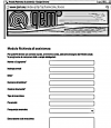 |
| Follow all instructions provided in the MIMAT manual | If the problem remains, fill out the “Request Form for assistance” on the page Contacts at www.qem.it site. Our technicians will get elements essential for the understanding of your problem. |
Repair
To provide you with an efficient service, please read and adhere to the instructions given here
Shipping
It is recommended to pack the instrument with materials that are able to cushion any falls.
 |  |  |
| Use the original package: it must protect the instrument during transport. | Attach: 1. A description of the anomaly; 2. A part of the electric scheme where the equipment is inserted 3. The planning of the equipment (set up, quotas of job, parameters…). 4. Request a quote for repair; if not required, the cost will be calculated in the final balance. | A full description of the problem, will help identify and resolve your problems fast. A careful packaging will avoid further inconveniences. |