目录
MDO_P1P20F - 022 : Operator Manual
1. Informations
1.1 Release
This document is valid except for errors or omissions.
| |
|||
| Document: | mdo_p1p20fh20-001 | ||
|---|---|---|---|
| Description: | Manual Operator p1p20f-022 | ||
| Editor: | Omar Sbalchiero | ||
| Approver | Gabriele Bazzi | ||
| Link: | https://www.qem.eu/doku/doku.php/en/strumenti/qmoveplus/j1p20/p1p20f-022/mdo_p1p20f-022 | ||
| Language: | English | ||
| Document release | Description | Note | Data |
| 01 | New manual | 31/08/2021 | |
1.1.1 Specifications
All rights reserved on this manual. No part of this document can be copied or reproduced in any form without prior written authorisation. QEM does not insure or guarantee its contents and explicitly declines all liability related to the guarantee of its suitability for any purpose. The information in this document can be changed without notice. QEM shall not be held liable for any error or omission in this document. QEM® is a registered trademark.Microsoft® and MS-DOS® are registered trademarks and Windows® is a trademark of Microsoft Corporation.
2. Description

The P1P20F - 022 software, controls the automation of machines sanders/edge-sanders.
Main features
-
control of 20 heads
-
control the sequential start of motors (to limit excessive power demand)
-
can manages the bridge movements
-
for each machining head, you can set processing advances/delays at the beginning/end of the piece
-
the ascent/descent controls of the sanding heads, are calculated automatically as the speed of the conveyor belt change
-
counts the processed meters and can work up to 30 pieces simultaneously
Other features
-
HMI with touchscreen
-
Function keys
-
Working program
-
Alarm messages
-
Warning messages
-
Reset defective pieces
-
Reset of all workpieces
-
Compensation of the offset of the piece presence limit switch
-
Mode of heads processing
-
Smoothing
-
Milling
-
Grinding
-
Brushing
-
Water jet
3. Main page

3.1 Control bars and informations
The bars at the top and bottom of each page provide the following informations:

A Machine status B Page name C Additional page description D Page number E Clock F Active alarm (red background) G Warning (azure background) 
Current conveyor belt speed N: Setting the conveyor belt speed P: Setting the bridge speed 
Bridge position.
N.B. The position of the Bridge is enabled only if the encoder is present on the axis of the Bridge
Machined linear meters 
Total number of pieces machined 
Number of parts currently being machined 
Last workpiece length 3.2 Main Page 2
Pressing the key
 , you can access the second main page:

in addition to the information on the main page, you can see:
-
Heads status
-
The current speeds of the conveyor belt and the bridge.
N.B. The the speed of the Bridge can be showed, only if the encoder is present on the axis of the Bridge -
The status of the part presence input
Pressing the key
 , for return to the main page.
3.3 Main Page 3
From the main page 2, pressing the key
, you can access the third main page:

In addition to the information on the main page, are showed:
-
The bridge speed and position.
-
With the keys
 and
and  you can to vary the back and forward limits of the Bridge.
 -
With the key
 you can to start the search for homing of the Bridge
Pressing the key
, you can return to the main page 2.
N.B. The Main Page “3” is enable only if is present the encoder on the Bridge axis.
3.4 Machine status
Simbols Descriptions 
Manual 
Emergency 
Automatic 
Mode of operation 
Calibration 
Not initialized 3.5 Common keys
Simbol Description 

Scroll through programs 
Save and exit: the setup values are saved in the internal memory and run 
open the program 
Forward page 
Backward page 
Exit without saving: the setup values entered are not saved and the values in the internal memory are reloaded. 
Access to the MENU page 
Access to the SETUP (protected with password) 
Access to the WORKING PROGRAMS 
Access to the TOTAL PIECES RESET 
Access to the PARTIAL PIECES RESET 
Access the the ALARMS 
Exit from the page 4. Main menu
For access from the MAIN PAGE press the key


Alarms 
Access to programs 
Functions menu 
Diagnostics 
Bridge homing 
Access to the setup 5. Utilization
5.1 Startup
If the Bridge encoder is installed and enabled, when switched on, the instrument show the Main Page 3 and and it is requested to start the homing search to calibrate the position of the Bridge Axis.
Pressing the key
for start the homing search.
To the end of the homing search, the instrument show directly the Main Page.
5.2 Working program
For access to the “Working program” section:
-
press the F3 funcion key

-
or access the MENU page, pressing the F1 key
 than press the key

To select one of the work programs listed, you must tap on the corresponding line.
 and
and 
To scroll through the list of work programmes. Each page can display 5 programs at a time.
It is possible to move directly to the desired page by editing it on the title bar.
Switching to the Work Cycle Editing Function. 
Opens the selected work program to edit it. 5.2.1 Edit Workin Program
 →
→ 

Unique Value
Copy the parameters of the first head to all Enabled HeadsAutomatic program: execute the points 1 - 2 - 3 - 4 :
-
To change the program enter the values in the various fields, using the virtual keyboard.
-
Type on the field “ UNIQUE VALUE” for copy the parameters of the first head on the all heads
-
Set machining parameters
-
After completing the parameter entry, pressing F7 key and the save the program are show
 →
→ 
Notes:
-
1 = sander, 2 = milling machine, 3 = grind, 4 = brush, 5 = water jet
-
if the heads are all of type 1 - 4 - 5, or all of the type 2, or all of the type 3, you can set “ all heads ”, or “ single head ”
-
if are set mix of types 1 - 2 - 3 then the choice “single heas” are disable.
5.2.2 Sander machine parameters
By default the machining parameters are all at 0.
Parameter name Units of measurement Range Description Advance(-)/Delay (+) head descent mm 0 ÷ 99999.0
Advance or delay spacehead descent from the beginning of the piece . Advance(+)/Delay (-) head ascent mm 0 ÷ 99999.0 head ascent from the end of the piece. .
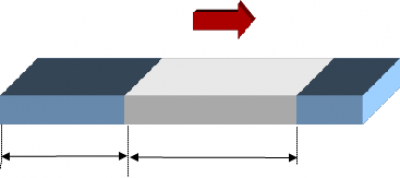
Polished piece only in the central part Piece entirely polished 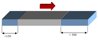

Advance(+)/Delay (-)
head ascent = +150Advance(-)/Dealy (+)
head descent = +300Advance(+)/Dealy (-)
head ascent = 000Advance(-)/Delay (+)
head descent = 0005.2.3 Milling machine parameters
Parameter name Units of measurement Range Description 
mm 0 ÷ 99999.0 Distance piece beginning / milling. It is the space between the beginning of the piece and the beginning of the milling process. 
mm 0 ÷ 99999.0 Distance piece ending / milling. It is the space between the end of the piece and the end of the milling working. 
mm 0 ÷ 99999.0 Milling length. It's the milling space. NB: If one of the two distance parameters is greater than zero, the other is automatically set to -1 (parameter value disabled).
Milling with reference from begin of workpiece Milling with reference from the end of the workpiece 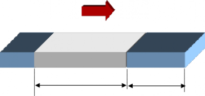
Milled space
Parameter:
milling lengthUnsead space
Parameter:
starting piece distanceUnsead space
Parameter:
end piece distanceMilled space
Parameter:
milling length5.2.4 Grinding wheel parameters
Parameter name Units of measurement Range Description 
mm 0 ÷ 99999.0 Worked linear meters. Space beyond which the grinding wheel wear compensation is activated. 
sec. 0 ÷ 99999.0 Head activation time. Activation time, the head performs a forward shift to compensate for the wear of the grinding wheel. 5.2.5 Brush parameters
The parameters are similar to the sander processing.
5.2.6 Water jet parameters
The parameters are similar to the sander processing.
6. Work functions
To select the desired work functions, press the key
 e poi sul tasto


Manual/Automatic page 
* Start: Automatic machine start-up with heads rotation
* Stop: Automatic machine start-up without heads rotation
Go to the Piece Reset page 6.1 Manual / Automatic
To select the function of choosing the working mode, presse the key

The following page is showed:


Operation mode selection MANUAL 
Operation mode selection AUTOMATIC 6.1.1 Manual
To select the MANUAL mode operation, press the key

The following page is Showed:

Description of possible operations in manual mode 
Press the keys  and
and  you can move the conveyor belt.
Pressing the keys and it's possible to move the Bridge.

 –> Back Limit Switch and Back Slowdown.
 –> Slowdown Forward and Limit Switch Forward.
N.B. Bride jog (MP-04 = 1)
Selection of the Head to be moved
N.B. In manual it is possible to move only one head at a time
Pressing the keys  and
and  it is possible to go up and descend the selected head
Pressing the keys and
and  you can turn on/off the spindle rotation of the selected head
6.1.2 Automatic
To select the AUTOMATIC mode operation, press the key

The instrument goes to the Main Page and is ready to acquire the parts in the machine.
6.2 Pieces reset
To select the pieces RESET, press the key

The following page is showed:


Reset of all pieces

Reset of selected pieces6.2.1 Reset of all pieces
To select the pieces RESET, press the key

The following page is showed:


Reset of all pieces
Note :
wait until the function is complete6.2.2 Reset of parts selections
To select the RESET of parts selection, press the key

The following page are showed:

IN PROGRESS –> Pieces inside the machine.
SELECTED –> Sum of selected pieces.
QI –> Space between the piece detection sensor (INP_09) and the start of the piece.
QF –> Space between the piece detection sensor (INP_09) and the end of the piece.
L –> Piece length.
HEADS –> <> The piece is between the two heads.Press the key
 to select the pieces present in the heads beyond the nr. 08.

Select the piece(s) to cancel. Press the key
The following page are showed:

Press the key
 , for reset the piece(s) to cancel.
Note: wait until the Reset is complete.
7. Diagnostic
For access to diagnostic, from the MENU page press the key


From this page you can access the various diagnostic sections:

Digital inputs 
Digital outputs 
Counters 
Analog inputs/outputs 
CAN connection informations 
System informations To return on the MENU press the key

7.1 Digital inputs
For acces to the diagnostic page of the Digital Inputs, press the key


For return to the DIAGNOSTIC menu, press the key
7.2 Digital outputs
For access to the diagnostic page of the Digital Outputs, press the key


For return to the DIAGNOSTIC menu, press the key
7.3 Counters
For acces to the diagnostic page of the Counters, press the key

For return to the DIAGNOSTIC menu, press the key
7.4 Analog outputs
For access to the Diagnostic page of the Analog Outputs, press the key

The analog output is indicated in Volt.
For return to the DIAGNOSTIC menu, press the key
7.5 CAN Connection Informations
For access to the diagnostic page of the CanOpen Connection, press the key

For return to the DIAGNOSTIC menu, press the key
7.6 System Informations
For access to the diagnostic page of the “System Informations”, press the key

Fw name firmware and checksum Aux fw firmware of the I/O module Task time CPU cycle time : Minimum, Middle, Maximum CPU time CPU time in Run state (hh:mm) Touch screen Test touch For return to the DIAGNOSTIC menu, press the key
8. Warning messages
Message Description Too many parts in the machine In the machine there are more than 30 pieces Waiting for auxiliary activation… Waiting for auxiliary activation (with parameter MP-08 enable)(I4 = ON) Abrasive replacement dimension positioning… The bridge is controlled in the abrasive replacement position Auxiliaries disabled Auxiliaries disabled (I4 = OFF) Attenzion!!! Motors off. Conveyor belt Start attempt with motors off 9. Alarms
For access to the ALARMS page, press the key

Press the key
 for cancel the alarm
Message Cause Input Pressed emergency Check the emergency line I01 Fault Inverter Check inverter I12 Conveyor belt encoder break Check conveyor belt encoder (Active only with parameter MP-03 > 2). Thermal protections Check thermal protections I06 Carter Check perimeter protections I07 Lack of air Check the pressure switch I08 The “Conveyor belt encoder break” message is automatically generated, if within 5 seconds a space of more than 2 units of measurement has not been cover,
the message is generated if the instrument detects a speed of less than 60mm per minute9.1 Alarm history
For access to the ALARMS, press the key


After removing the causes of the alarm, press (x 3 sec.) the key
to delete
Maximum 60 alarms.
10. Assistance
For supplying you fast service, at the lowest cost, we need your support.

Follow all instructions provided in the MIMAT manual If the problem remains, fill out the “Request Form for assistance” on the page Contacts at www.qem.it site.
Our technicians will get elements essential for the understanding of your problem.Repair
To provide you with an efficient service, please read and adhere to the instructions given here
Shipping
It is recommended to pack the instrument with materials that are able to cushion any falls.


Use the original package: it must protect the instrument during transport. Attach:
1. A description of the anomaly;
2. A part of the electric scheme where the equipment is inserted
3. The planning of the equipment (set up, quotas of job, parameters…).
4. Request a quote for repair; if not required, the cost will be calculated in the final balance.A full description of the problem, will help identify and resolve your problems fast. A careful packaging will avoid further inconveniences. -