Table of Contents
MCE_P1P44F-010: Connections
 |  |
1. Informations
1.1 Release
| |
|||
| Document: | mce_p1p44f-010 | ||
|---|---|---|---|
| Description: | p1p44f-010 Electrical Connections Manual | ||
| Editor: | Michele Sandri | ||
| Approver | Gabriele Bazzi | ||
| Link: | http://www.qem.eu/doku/doku.php/en/strumenti/qmoveplus/j1p44/p1p44f-010/mce_p1p44f-010 | ||
| Language: | English | ||
| Document release | Description | Note | Date |
| 01 | New manual | 17/02/2020 | |
| 02 | Add the Alarm 2 output on the second RMC-1S module | 09/07/2020 | |
| 03 | Can speed modifity to 500Kb | 17/02/2021 | |
| 04 | Add the I70 input and O63 output for hydraulic brakes (wedges) | 31/03/2021 | |
1.1.1 Specifications
The copyright of this manual is reserved. No part of this document can be copied or reproduced in any form without the prior written permission of the QEM.
QEM has no assurances or guarantees on the content and specifically disclaims any liability inherent in the guarantees of eligibility for any particular purpose. The information in this document is subject to change without notice. QEM does not take any responsibility for any errors that may appear in this document.
Trademarks:
-
QEM® is a registered trademark.
2. Hardware and connections
2.1 Instrument J1-P44-FB20
 |
|
 |
|
 | J1-P44-Fx:Installation and Maintenance Manual |
2.1.1 Power supply
2.1.1.1 CN1
The instrument should be powered at 24Vdc, provide an external fuse in series to the positive conductor +24Volt.
| PIN | ID | DESCRIPTION | |
|---|---|---|---|
 | 1 | +24V | Positive Power Supply Input +24Vdc |
| 2 | PE | Ground-PE | |
| 3 | 0V | Common Power Supply 0Vdc |
2.1.2 Connectivity
N. 1 PROG PORT → Serial with TTL logical standard for programming
N. 1 ETHERNET PORT
N. 1 USB port to save/load data from external memory
N. 1 CAN port connecting to external I/O modules
2.1.2.1 CN5
| PIN | ID | DESCRIPTION | |
|---|---|---|---|
 | 1 | 0V | Common CAN |
| 2 | CAN_L | Communication low signal | |
| 3 | CAN_H | Communication high signal |
2.1.2.1.1 J1-P44/RMC-1S/RMC-1S example of connections

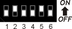
2.1.2.1.2 CAN port settings
| SW1 | Num. Dip | Set |
|---|---|---|
 | 1 | X |
| 2 | X | |
| 3 | X | |
| 4 | OFF | |
| 5 | ON | |
| 6 | X | |
| 7 | X | |
| 8 | X |
2.1.3 Digital inputs
| S = State | A = Action | ID |
|---|---|---|
| NO = Normally Open | I = Impulsive | ID = Software |
| NC = Normally Closed | C = Continuous |
2.1.3.1 CN7
| PIN | ID | DESCRIPTION | S | A | |||
|---|---|---|---|---|---|---|---|
 | 1 | 0V | Common of digital inputs | ||||
| 2 | I1 | Jog | X Axis | Forward | NO | I | |
| 3 | I2 | Backward | |||||
| 4 | I3 | Y Axis | Forward | ||||
| 5 | I4 | Backward | |||||
| 6 | I5 | Z Axis | Ascent | ||||
| 7 | I6 | Descent | |||||
| 8 | I7 | W Axis | Clockwise rotation | ||||
| 9 | I8 | Anti-clockwise rotation | |||||
2.1.3.1.1 Connections example

2.1.3.2 CN6
| PIN | ID | DESCRIPTION | S | A | |||
|---|---|---|---|---|---|---|---|
| | 1 | 0V | Common of digital inputs | ||||
| 2 | I9 | Manual / Automatic | OFF = Manual, ON = Automatic | NO | C | ||
| 3 | I10 | Start | I | ||||
| 4 | I11 | Stop | NC | C | |||
| 5 | I12 | Start disk rotation | NO | I | |||
| 6 | I13 | Stop disk rotation | NC | C | |||
| 7 | I14 | Slow/Fast Selector | OFF = slow, ON = fast | NO | |||
| 8 | I15 | Emergency | NC | ||||
| 9 | I16 | Available | - | - | |||
2.1.3.2.1 Connections example

2.1.3.3 CN15
| PIN | ID | DESCRIPTION | S | A | ||||
|---|---|---|---|---|---|---|---|---|
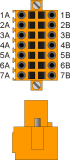 | 1A | +24V | Out +24Vdc | |||||
| 2A | PHA2 | JOG | H Axis | Forward | NO | I | ||
| 3A | PHB2 | Backward | ||||||
| 4A | Z2 | Y-Axis zeroing | ||||||
| 5A | 0V | n | Common of counter inputs - Internally connected to the 0Volt (PIN 3 - CN1) Connect to PIN 5B | |||||
| 6A | Connect to PIN 6B | |||||||
| 7A | Connect to PIN 7B | |||||||
2.1.3.3.1 Connections example

2.1.4 Counter inputs
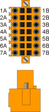
2.1.4.1 CN14
| PIN | ID | DESCRIPTION | |||
|---|---|---|---|---|---|
| | 1A | +24V | Encoder Power Supply Output | ||
| 2A | PHA1 | A Phase | Asse H | ||
| 3A | PHB1 | B Phase | |||
| 4A | Z1 | Z Phase | |||
| 5A | 0V | n | Common of counter inputs - Internally connected to the 0Volt (PIN 3 - CN1) Connect to PIN 5B |
||
| 6A | Connect to PIN 6B | ||||
| 7A | Connect to PIN 7B | ||||
2.1.4.1.1 Connection example

2.1.5 Digital outputs
| S = State | ID |
|---|---|
| OFF | ID = Software |
| ON |
2.1.5.1 CN9
| PIN | ID | DESCRIPTION | S | ||
|---|---|---|---|---|---|
 | 1 | V+ | Input of Power Supply outputs O1÷O4 (12÷28V dc) | ||
| 2 | O1 | Automatic Cycle | OFF | ||
| 3 | O2 | Allarm | |||
| 4 | O3 | Stopped Disk | |||
| 5 | O4 | Overcurrent Disk | |||
| 6 | V+ | Input of Power Supply outputs O5÷O8(12÷28V dc) | |||
| 7 | O5 | Buzzer | OFF | ||
| 8 | O6 | Raised bridge | |||
| 9 | O7 | Available | - | ||
| 10 | O8 | Available | - | ||
| 11 | V- | Input of Power Supply outputs (0V dc) | |||
2.1.5.1.1 Connections example

2.1.5.2 CN8
| PIN | ID | DESCRIPTION | S | ||
|---|---|---|---|---|---|
| 1 | V+ | Input of Power Supply outputs O9÷O12(12÷28V dc) | ||
| 2 | O9 | Available | - | ||
| 3 | O10 | Available | - | ||
| 4 | O11 | Available | - | ||
| 5 | O12 | Available | - | ||
| 6 | V+ | Input of Power Supply outputs O13÷O16(12÷28V dc) | |||
| 7 | O13 | Available | - | ||
| 8 | O14 | Available | - | ||
| 9 | O15 | Available | - | ||
| 10 | O16 | Available | - | ||
| 11 | V- | Input of Power Supply outputs (0V dc) | |||
2.1.6 Analog inputs
2.1.6.1 CN13
| PIN | ID | DESCRIPTION | |||
|---|---|---|---|---|---|
 | 1 | VREF | Reference voltage Output to 2,5Volt | ||
| 2 | AI1 | Speed Potentiometer | Asse X | Avanti | |
| 3 | AI2 | Indietro | |||
| 4 | AI3 | Available | |||
| 5 | GAI | Common of analog inputs | |||
2.1.6.1.1 Connections example

2.1.6.2 Setting of analog inputs
| SW4 | Num. Dip | Set |
|---|---|---|
 | 1 | OFF |
| 2 | OFF | |
| 3 | OFF | |
| 4 | OFF | |
| 5 | X | |
| 6 | X |
2.1.7 Analog outputs
2.1.7.1 CN12
| PIN | ID | DESCRIPTION | |
|---|---|---|---|
 | 1 | GAO | Common of analog outputs |
| 2 | AO1 | H Axis (0-10 Vdc o +/-10V) | |
| 3 | AO2 | Cutting Disk (0-10 Vdc) | |
| 4 | GAO | Common of analog outputs | |
| 5 | AO3 | Available | |
| 6 | AO4 | Available |
2.1.7.1.1 Connections example

2.2 RMC-1SC01E1/MG2/24Vdc Expansion (1° Module)
 |
|
 |
|
| | RMC-1SC01:Installation and Maintenance Manual |
2.2.1 Power Supply
2.2.1.1 CN1
The instrument should be powered at 24Vdc, provide an external fuse in series to the positive conductor +24Volt.
| PIN (NUMBER) | ID | DESCRIPTION | |
|---|---|---|---|
 | 1 (1) | 0V | Common of Power Supply 0V |
| 2 (2) | PE | Ground-PE | |
| 3 (3) | +24V | Positive of Power Supply Input +24V |
2.2.2 Connectivity
2.2.2.1 CN2
| PIN (NUMBER) | ID | DESCRIPTION | |
|---|---|---|---|
| | 1 (4) | 0V | Common CAN |
| 2 (5) | CAN_L | Communication CAN low signal | |
| 3 (6) | CAN_H | Communication CAN high signal |
2.2.2.2 CN3
| PIN (NUMBER) | ID | DESCRIPTION | |
|---|---|---|---|
| | 1 (7) | 0V | Common CAN |
| 2 (8) | CAN_L | Communication CAN low signal | |
| 3 (9) | CAN_H | Communication CAN high signal |
2.2.2.2.1 Connections example
2.2.2.2.2 Terminating Resistance Setting
Setting of terminating resistances for the Canbus line.
| SW1 | N. Dip | DIP Settings | Function |
|---|---|---|---|
 | 1 | / | without |
| 2 | / | ||
| 3 | OFF | Resistances Not Inserted | |
| 4 | OFF |
2.2.2.2.3 DIP-SWITCH SW2
Functions Description
| SW2 | N. DIP | Function | |
|---|---|---|---|
 | Selecting the Transmission Speed of the Canbus | 1 | OFF |
| 2 | ON | ||
| Baud-Rate | 500Kb | ||
| Selecting the address of the Canbus slave module | 3 | ON | |
| 4 | OFF | ||
| 5 | OFF | ||
| 6 | OFF | ||
| ID | 1 |
2.2.3 Digital inputs
| S = State | A = Action | ID |
|---|---|---|
| NO = Normally Open | I = Impulsive | ID = Software |
| NC = Normally Closed | C = Continuous |
2.2.3.1 CN6
| PIN (NUMBER) | ID | DESCRIPTION | S | A | |||
|---|---|---|---|---|---|---|---|
 | 1 (34) | I51 | Emergency | NC | C | ||
| 2 (35) | I52 | Limit switch | X Axis | Forward | |||
| 3 (36) | I53 | Backward | |||||
| 4 (37) | I54 | Y Axis | Forward | ||||
| 5 (38) | I55 | Backward | |||||
| 6 (39) | I56 | Z Axis | Top | ||||
| 7 (40) | I57 | Bottom | |||||
| 8 (41) | I58 | Stateflow | |||||
| 9 (42) | PL1 | Polarizer | |||||
| 10 (43) | I59 | Zero Cam | X Axis | NO | C | ||
| 11 (44) | I60 | Y Axis | |||||
| 12 (45) | I61 | Z Axis | |||||
| 13 (46) | I62 | W Axis | |||||
| 14 (47) | I63 | W and H fault inverters 1) | NC | ||||
| 15 (48) | I64 | Disk fault inverter | |||||
| 16 (49) | I65 | Thermal switch series | |||||
| 17 (50) | I66 | Moving disk | NO | ||||
| 18 (51) | PL2 | Polarizer | |||||
2.2.3.1.1 NPN logic connections example

2.2.3.1.2 PNP logic connections example

We suggested to choose the connection with PNP logic
2.2.4 Counter inputs
2.2.4.1 CN7
| PIN (NUMBER) | ID | Description | |||
|---|---|---|---|---|---|
 | 1A (52A) | Internal bridge 1A -1B | |||
| 2A (53A) | PHA3 | A Phase | X Axis | PNP Push-Pull 12-24V1) | |
| 3A (54A) | PHB3 | B Phase | |||
| 4A (55A) | Z3 | Z Pulse | |||
| 5A (56A) | 0V | Common encoder input | |||
| 6A (57A) | 0V | ||||
| 7A (58A) | 0V | ||||
| 1B (52B) | Internal bridge 1A -1B | ||||
| 2B (53B) | PHA3+ | A+ Phase | X Axis | Line Driver only 5V | |
| 3B (54B) | PHB3+ | B+ Phase | |||
| 4B (55B) | Z3+ | Z+ Pulse | |||
| 5B (56B) | PHA3- | A- Phase | |||
| 6B (57B) | PHB3- | B- Phase | |||
| 7B (58B) | Z3- | Z- Pulse | |||
Terminal 5B (56B): connect to the 5A terminal (56A)
Terminal 6B (57B): connect to the 6A terminal (57A)
Terminale 7B (58B): connect to the 7A terminal (58A)
2.2.4.1.1 Connections example

2.2.4.2 CN8
| PIN (NUMBER) | ID | Description | |||
|---|---|---|---|---|---|
| | 1A (59A) | Internal bridge 1A -1B | |||
| 2A (60A) | PHA4 | A Phase | Y Axis | PNP Push-Pull 12-24V1) | |
| 3A (61A) | PHB4 | B Phase | |||
| 4A (62A) | Z4 | Z Pulse | |||
| 5A (63A) | 0V | Common encoder input | |||
| 6A (64A) | 0V | ||||
| 7A (65A) | 0V | ||||
| 1B (59B) | Internal bridge 1A -1B | ||||
| 2B (60B) | PHA4+ | A+ Phase | Y Axis | Line Driver only 5V | |
| 3B (61B) | PHB4+ | B+ Phase | |||
| 4B (62B) | Z4+ | Z+ Pulse | |||
| 5B (63B) | PHA4- | A- Phase | |||
| 6B (64B) | PHB4- | B- Phase | |||
| 7B (65B) | Z4- | Z- Pulse | |||
Terminal 5B (63B): connect to the 5A terminal 5A (63A)
Terminal 6B (64B): connect to the 6A terminal (64A)
Terminal 7B (65B): connect to the 7A terminal (65A)
2.2.4.2.1 Connections example

2.2.5 Analog outputs / Analog inputs
2.2.5.1 CN9
| PIN (NUMBER) | ID | Description | |
|---|---|---|---|
 | 1A (66A) | AO5 | X Axis (0-10 Vdc or +/-10V) |
| 2A (67A) | GAO | Common analog outputs | |
| 3A (68A) | n.c. | ||
| 4A (69A) | Vref | ||
| 5A (70A) | Sel.1 Curr. 1) | ||
| 6A (71A) | Sel.1 Volt 2) | ||
| 7A (72A) | AI4 | Disk motor absorption (0-10Vdc) | |
| 8A (73A) | GAI | Common analog inputs | |
| 1B (66B) | AO6 | Y Axis (0-10 Vdc or +/-10V) | |
| 2B (67B) | GAO | Common analog outputs | |
| 3B (68B) | n.c. | ||
| 4B (69B) | Vref | ||
| 5B (70B) | Sel.2 Curr. 3) | ||
| 6B (71B) | Sel.2 Volt 4) | ||
| 7B (72B) | AI5 | RPM disk (0-10Vdc) | |
| 8B (73B) | GAI | Common analog inputs |
2.2.5.1.1 Connection example

2.2.6 Digital outputs
| S = State | ID |
|---|---|
| OFF | ID = Software |
| ON |
2.2.6.1 CN4
| PIN (NUMBER) | ID | DESCRIPTION | S | |||
|---|---|---|---|---|---|---|
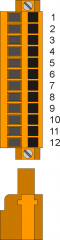 | 1 (10) | V+ | Input of Power Supply outputs O33÷O36 (12÷28V dc) | |||
| 2 (11) | O33 | Water | OFF | |||
| 3 (12) | O34 | Laser | ||||
| 4 (13) | O35 | X Axis | Forward | |||
| 5 (14) | O36 | Backward | ||||
| 6 (15) | V- | Input of Power Supply outputs (0V dc) | ||||
| 7 (16) | V+ | Input of Power Supply outputs O37÷O40 (12÷28V dc) | ||||
| 8 (17) | O37 | Y Axis | Forward | OFF | ||
| 9 (18) | O38 | Backward | ||||
| 10 (19) | O39 | Z Axis | Ascent | |||
| 11 (20) | O40 | Descent | ||||
| 12 (21) | V- | Input of Power Supply outputs (0V dc) | ||||
2.2.6.1.1 Connection example

2.2.6.2 CN5
| CN5 | PIN (NUMBER) | ID | DESCRIPTION | S | ||
|---|---|---|---|---|---|---|
| | 1 (22) | V+ | Input of Power Supply outputs O41÷O44 (12÷28V dc) | |||
| 2 (23) | O41 | W Axis | Clockwise | OFF | ||
| 3 (24) | O42 | Counter clokwise | ||||
| 4 (25) | O43 | Brake | X Axis | 1) | ||
| 5 (26) | O44 | Y Axis | ||||
| 6 (27) | V- | Input of Power Supply outputs (0V dc) | ||||
| 7 (28) | V+ | Input of Power Supply outputs O45÷O48 (12÷28V dc) | ||||
| 8 (29) | O45 | Brake | Z Axis | 2) | ||
| 9 (30) | O46 | W Axis | ||||
| 10 (31) | O47 | End program | OFF3) | |||
| 11 (32) | O48 | Machine OK | ON | |||
| 12 (33) | V- | Input of Power Supply outputs (0V dc) | ||||
2.2.6.2.1 Connection example

2.3 RMC-1SC01E1/MG2/24Vdc Expansion (2° module)
| |
|
| |
|
| | RMC-1SC01:Installation and Maintenance Manual |
2.3.1 Power Supply
2.3.1.1 CN1
The instrument should be powered at 24Vdc, provide an external fuse in series to the positive conductor +24Volt.
| PIN (NUMBER) | ID | DESCRIPTION | |
|---|---|---|---|
| | 1 (1) | 0V | Common of Power Supply 0V |
| 2 (2) | PE | Ground-PE | |
| 3 (3) | +24V | Positive of Power Supply Input +24V |
2.3.2 Connectivity
2.3.2.1 CN2
| PIN (NUMBER) | ID | DESCRIPTION | |
|---|---|---|---|
| | 1 (4) | 0V | Common CAN |
| 2 (5) | CAN_L | Communication CAN low signal | |
| 3 (6) | CAN_H | Communication CAN high signal |
2.3.2.1.1 Connection example
2.3.2.1.2 Terminating Resistance Setting
Setting of terminating resistances for the Canbus line.
| SW1 | N. Dip | DIP Settings | Function |
|---|---|---|---|
| | 1 | / | without |
| 2 | / | ||
| 3 | ON | Resistances Inserted | |
| 4 | ON |
2.3.2.1.3 DIP-SWITCH SW2
Descrizione funzionalità
| SW2 | N. DIP | Function | |
|---|---|---|---|
| | Selecting the Transmission Speed of the Canbus | 1 | OFF |
| 2 | ON | ||
| Baud-Rate | 500Kb | ||
| Selecting the address of the Canbus slave module | 3 | OFF | |
| 4 | ON | ||
| 5 | OFF | ||
| 6 | OFF | ||
| ID | 2 |
2.3.3 Digital inputs
| S = State | A = Action | ID |
|---|---|---|
| NO = Normally Open | I = Impulsive | ID = Software |
| NC = Normally Closed | C = Continuous |
2.3.3.1 CN6
| PIN (NUMBER) | ID | DESCRIPTION | S | A | |||
|---|---|---|---|---|---|---|---|
| | 1 (34) | I67 | Zero Cam | H Axis | NO | C | |
| 2 (35) | I68 | Limit switch | H Axis | Forward | NC | ||
| 3 (36) | I69 | Backward 1) | |||||
| 4 (37) | I70 | Pressure switch | W and H axes | Connect in parallel If active, the W or H axes can be moved | NO | - | |
| 5 (38) | I71 | Available | - | - | |||
| 6 (39) | I72 | 45° dowel pins | Dowel pins multiple W position 45° inserted | NO | C | ||
| 7 (40) | I73 | Generic dowel pins | Generic W position dowel pins inserted | ||||
| 8 (41) | I74 | Active auxiliaries | NC | ||||
| 9 (42) | PL1 | Polarizer | |||||
| 10 (43) | I75 | Active barriers | NC | C | |||
| 11 (44) | I76 | Disk absorption alarm | |||||
| 12 (45) | I77 | Air pressure switch | |||||
| 13 (46) | I78 | Oil pressure switch | |||||
| 14 (47) | I79 | Bridge lifting | |||||
| 15 (48) | I80 | Fault | X Axis | ||||
| 16 (49) | I81 | Y Axis | |||||
| 17 (50) | I82 | Z Axis | |||||
| 18 (51) | PL2 | Polarizer | |||||
2.3.3.1.1 NPN logic connections example

2.3.3.1.2 PNP logic connections example

We suggested to choose the connection with PNP logic
2.3.4 Counter inputs
2.3.4.1 CN7
| PIN (NUMBER) | ID | Description | |||
|---|---|---|---|---|---|
| | 1A (52A) | Internal bridge 1A -1B | |||
| 2A (53A) | PHA5 | A Phase | Z Axis | PNP Push-Pull 12-24V1) | |
| 3A (54A) | PHB5 | B Phase | |||
| 4A (55A) | Z5 | Z Pulse | |||
| 5A (56A) | 0V | Common encoder input | |||
| 6A (57A) | 0V | ||||
| 7A (58A) | 0V | ||||
| 1B (52B) | Internal bridge 1A -1B | ||||
| 2B (53B) | PHA5+ | A+ Phase | Z Axis | Line Driver only 5V | |
| 3B (54B) | PHB5+ | B+ Phase | |||
| 4B (55B) | Z5+ | Z+ Pulse | |||
| 5B (56B) | PHA5- | A- Phase | |||
| 6B (57B) | PHB5- | B- Phase | |||
| 7B (58B) | Z5- | Z- Pulse | |||
Terminal 5B (56B): connect to the 5A terminal (56A)
Terminal 6B (57B): connect to the 6A terminal (57A)
Terminal 7B (58B): connect to the 7A terminal (58A)
2.3.4.1.1 Push Pull encoder connection example

2.3.4.2 CN8
| PIN (NUMBER) | ID | Description | |||
|---|---|---|---|---|---|
| | 1A (59A) | Internal bridge 1A -1B | |||
| 2A (60A) | PHA6 | A Phase | W Axis | PNP Push-Pull 12-24V1) | |
| 3A (61A) | PHB6 | B Phase | |||
| 4A (62A) | Z6 | Z Pulse | |||
| 5A (63A) | 0V | Common encoder input | |||
| 6A (64A) | 0V | ||||
| 7A (65A) | 0V | ||||
| 1B (59B) | Internal bridge 1A -1B | ||||
| 2B (60B) | PHA6+ | A+ Phase | W Axis | Line Driver only 5V | |
| 3B (61B) | PHB6+ | B+ Phase | |||
| 4B (62B) | Z6+ | Z+ Pulse | |||
| 5B (63B) | PHA6- | A- Phase | |||
| 6B (64B) | PHB6- | B- Phase | |||
| 7B (65B) | Z6- | Z- Pulse | |||
Terminal 5B (63B): connect to the 5A terminal (63A)
Terminal 6B (64B): connect to the 6A terminal (64A)
Terminal 7B (65B): connect to the 7A terminal (65A)
2.3.4.2.1 Push Pull encoder connection example

2.3.5 Analog outputs / Analog inputs
2.3.5.1 CN9
| PIN (NUMBER) | ID | Description | |
|---|---|---|---|
| | 1A (66A) | AO7 | Z Axis (0-10 Vdc o +/-10V) |
| 2A (67A) | GAO | Common analog outputs | |
| 3A (68A) | n.c. | ||
| 4A (69A) | Vref | ||
| 5A (70A) | Sel.1 Curr. 1) | ||
| 6A (71A) | Sel.1 Volt 2) | ||
| 7A (72A) | AI6 | Available | |
| 8A (73A) | GAI | Common analog inputs | |
| 1B (66B) | AO8 | W Axis (0-10 Vdc o +/-10V) | |
| 2B (67B) | GAO | Common analog outputs | |
| 3B (68B) | n.c. | ||
| 4B (69B) | Vref | ||
| 5B (70B) | Sel.2 Curr. 3) | ||
| 6B (71B) | Sel.2 Volt 4) | ||
| 7B (72B) | AI7 | Disponibile | |
| 8B (73B) | GAI | Common analog inputs |
2.3.5.1.1 Connection example

2.3.6 Digital outputs
| S = State | ID |
|---|---|
| OFF | ID = Software |
| ON |
2.3.6.1 CN4
| PIN (NUMBER) | ID | DESCRIPTION | S | |||
|---|---|---|---|---|---|---|
| | 1 (10) | V+ | Input of Power Supply outputs O49÷O52 (12÷28V dc) | |||
| 2 (11) | O49 | H Axis | Forward | OFF | ||
| 3 (12) | O50 | Backward | ||||
| 4 (13) | O51 | Brake | 1) | |||
| 5 (14) | O52 | Slowdown | Y Axis | OFF | ||
| 6 (15) | V- | Input of Power Supply outputs (0V dc) | ||||
| 7 (16) | V+ | Input of Power Supply outputs O53÷O56 (12÷28V dc) | ||||
| 8 (17) | O53 | Slowdown | W Axis | OFF | ||
| 9 (18) | O54 | Last cut | ||||
| 10 (19) | O55 | 45° dowel pins | Dowel pins 45° or multiple inserted | |||
| 11 (20) | O56 | Generic dowel pins | Dowel pins generic position inserted | |||
| 12 (21) | V- | Input of Power Supply outputs (0V dc) | ||||
2.3.6.1.1 Connection example

2.3.6.2 CN5
| CN5 | PIN (NUMBER) | ID | DESCRIPTION | S | ||
|---|---|---|---|---|---|---|
| | 1 (22) | V+ | Input of Power Supply outputs O41÷O44 (12÷28V dc) | |||
| 2 (23) | O57 | Piece blocker | Lock the pieces during cutting | OFF | ||
| 3 (24) | O58 | Lubrication | ||||
| 4 (25) | O59 | Disk inverter startup | In setup, choose if to use as a disk startup or motion consent |
|||
| 5 (26) | O60 | Reset inverter | Active for 2 seconds at alarm reset | |||
| 6 (27) | V- | Input of Power Supply outputs (0V dc) | ||||
| 7 (28) | V+ | Input of Power Supply outputs O45÷O48 (12÷28V dc) | ||||
| 8 (29) | O61 | Slowdown | H Axis | OFF | ||
| 9 (30) | O62 | Alarm 2 | Activates with the O2 Alarm output | |||
| 10 (31) | O63 | Hydraulic brake control unit W and H Axes | It activates to extract the wedges and remains active during the movement of the axes | |||
| 11 (32) | O64 | Available | - | |||
| 12 (33) | V- | Input of Power Supply outputs (0V dc) | ||||
2.3.6.2.1 Connection example

3. Assistance
For supplying you fast service, at the lowest cost, we need your support.
 |  |
| Follow all instructions provided in the MIMAT manual | If the problem remains, fill out the “Request Form for assistance” on the page Contacts at www.qem.it site. Our technicians will get elements essential for the understanding of your problem. |
Repair
To provide you with an efficient service, please read and adhere to the instructions given here
Shipping
It is recommended to pack the instrument with materials that are able to cushion any falls.
 |  |  |
| Use the original package: it must protect the instrument during transport. | Attach: 1. A description of the anomaly; 2. A part of the electric scheme where the equipment is inserted 3. The planning of the equipment (set up, quotas of job, parameters…). 4. Request a quote for repair; if not required, the cost will be calculated in the final balance. | A full description of the problem, will help identify and resolve your problems fast. A careful packaging will avoid further inconveniences. |