 | Le caratteristiche elettriche sono riportate nel paragrafo Caratteristiche elettriche. Gli esempi di collegamento sono riportati nel paragrafo Esempi di collegamento |
|---|
| CN23 | Morsetto | Simbolo | Descrizione | Indirizzo | |
|---|---|---|---|---|---|
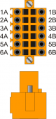 | 1A | - | n.c. | ||
| 2A | DIR1+ | Uscita DIREZIONE 1 | Push-Pull Line Driver | 3.PULSE01 | |
| 3A | STEP1+ | Uscita STEP 1 | |||
| 4A | DIR2+ | Uscita DIREZIONE 2 | 3.PULSE02 | ||
| 5A | STEP2+ | Uscita STEP 2 | |||
| 6A | 0V | Comune delle uscite stepper | |||
| 1B | - | n.c. | |||
| 2B | DIR1- | Uscita complementare DIREZIONE 1 | Uscite complementari per l'utilizzo nei drive con ingressi Line-Driver | ||
| 3B | STEP1- | Uscita complementare STEP 1 | |||
| 4B | DIR2- | Uscita complementare DIREZIONE 2 | |||
| 5B | STEP2- | Uscita complementare STEP 2 | |||
| 6B | 0V | Comune delle uscite stepper | |||
| CN24 | Morsetto | Simbolo | Descrizione | Indirizzo | |
|---|---|---|---|---|---|
| | 1A | - | n.c. | ||
| 2A | DIR3+ | Uscita DIREZIONE 3 | Push-Pull Line Driver | 3.PULSE03 | |
| 3A | STEP3+ | Uscita STEP 3 | |||
| 4A | DIR4+ | Uscita DIREZIONE 4 | 3.PULSE04 | ||
| 5A | STEP4+ | Uscita STEP 4 | |||
| 6A | 0V | Comune delle uscite stepper | |||
| 1B | - | n.c. | |||
| 2B | DIR3- | Uscita complementare DIREZIONE 3 | Uscite complementari per l'utilizzo nei drive con ingressi Line-Driver | ||
| 3B | STEP3- | Uscita complementare STEP 3 | |||
| 4B | DIR4- | Uscita complementare DIREZIONE 4 | |||
| 5B | STEP4- | Uscita complementare STEP 4 | |||
| 6B | 0V | Comune delle uscite stepper | |||
| CN25 | Morsetto | Simbolo | Descrizione | Indirizzo | |
|---|---|---|---|---|---|
| | 1A | - | n.c. | ||
| 2A | DIR5+ | Uscita DIREZIONE 5 | Push-Pull Line Driver | 3.PULSE05 | |
| 3A | STEP5+ | Uscita STEP 5 | |||
| 4A | - | n.c. | |||
| 5A | - | n.c. | |||
| 6A | 0V | Comune delle uscite stepper | |||
| 1B | - | n.c. | |||
| 2B | DIR5- | Uscita complementare DIREZIONE 5 | Uscite complementari per l'utilizzo nei drive con ingressi Line-Driver | ||
| 3B | STEP5- | Uscita complementare STEP 5 | |||
| 4B | - | n.c. | |||
| 5B | - | n.c. | |||
| 6B | 0V | Comune delle uscite stepper | |||