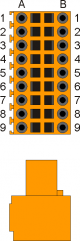
Composizione bus gamma H9
SLOT 3 (H1-TT0)
| Pin | Nome Name | Descrizione Description | Indirizzo Address |
|
|---|---|---|---|---|
 | 1A | COM1 | Digital output 1-8 common voltage (12÷28 dc volts) | |
| 2A | O1 | Digital output 1 | X.OUT01 | |
| 3A | O2 | Digital output 2 | X.OUT02 | |
| 4A | O3 | Digital output 3 | X.OUT03 | |
| 5A | PE | Earth | ||
| 6A | TC1+ | Thermocouple 1 positive input | X.AI01 | |
| 7A | TC1- | Thermocouple 1 negative input | ||
| 8A | TC2+ | Thermocouple 2 positive input | X.AI02 | |
| 9A | TC2- | Thermocouple 2 negative input | ||
| 1B | I1 | Digital input I1 | X.INP01 | |
| 2B | I2 | Digital input I2 | X.INP02 | |
| 3B | I3 | Digital input I3 | X.INP03 | |
| 4B | O4 | Digital output 4 | X.OUT04 | |
| 5B | PE | Earth | ||
| 6B | TC3+ | Thermocouple 3 positive input | X.AI03 | |
| 7B | TC3- | Thermocouple 3 negative input | ||
| 8B | TC4+ | Thermocouple 4 positive input | X.AI04 | |
| 9B | TC4- | Thermocouple 4 negative input |
N.B.: X.AI5 valore temperatura ambiente
SLOT 4 (H1-MH0)
| Pin | Nome Name | Descrizione Description | Indirizzo Address |
|
|---|---|---|---|---|
| | 1A | +24V | OUT 24Volt | |
| 1B | ||||
| 2A | PHA1 | “A” channel bidirectional counter 1 | X.CNT01 \ X.INP06 | |
| 3A | PHA2 | “A” channel bidirectional counter 2 | X.CNT02 \ X.INP09 | |
| 2B | PHB1 | “B” channel bidirectional counter 1 | X.CNT01 \ X.INP07 | |
| 3B | PHB2 | “B” channel bidirectional counter 2 | X.CNT02 \ X.INP10 | |
| 4A | PHZ1 | “Z” channel bidirectional counter 1 | X.INP08 | |
| 4B | PHZ2 | “Z” channel bidirectional counter 2 | X.INP11 | |
| 5A | 0 V | Encoders & digital input 0 Volts | ||
| 5B | ||||
| 6A | - | Non utilizzato | ||
| 6B | - | Non utilizzato | ||
| 7A | VM+ | Alimentazione motori (18÷28 dc volts) | ||
| 7B | VM- | |||
| 8A | M1A | Uscite motore 1 | X.AN01 | |
| 8B | M1B | |||
| 9A | M2A | Uscite motore 2 | X.AN02 | |
| 9B | M2B |
Segnali comando motori
| Nome Name | Descrizione Description | Tipo Type | Indirizzo Address |
|---|---|---|---|
| FLT01 | Fault motore 1 | Input | X.INP04 |
| DIR01 | Direzione motore 1 | Output | X.OUT05 |
| MOV01 | Movimento motore 1 | Output | X.OUT06 |
| ENA01 | Abilitazione motore 1 | Output | X.OUT07 |
| FLT02 | Fault motore 2 | Input | X.INP05 |
| DIR02 | Direzione motore 2 | Output | X.OUT08 |
| MOV02 | Movimento motore 2 | Output | X.OUT09 |
| ENA02 | Abilitazione motore 2 | Output | X.OUT10 |
SLOT 5 (H1-MH0)
| Pin | Nome Name | Descrizione Description | ||
|---|---|---|---|---|
| | 1A | +24V | OUT 24Volt | |
| 1B | ||||
| 2A | PHA1 | “A” channel bidirectional counter 1 | X.CNT03 \ X.INP14 | |
| 3A | PHA2 | “A” channel bidirectional counter 2 | X.CNT04 \ X.INP17 | |
| 2B | PHB1 | “B” channel bidirectional counter 1 | X.CNT03 \ X.INP15 | |
| 3B | PHB2 | “B” channel bidirectional counter 2 | X.CNT04 \ X.INP18 | |
| 4A | PHZ1 | “Z” channel bidirectional counter 1 | X.INP16 | |
| 4B | PHZ2 | “Z” channel bidirectional counter 2 | X.INP19 | |
| 5A | 0 V | Encoders & digital input 0 Volts | ||
| 5B | ||||
| 6A | - | Non utilizzato | ||
| 6B | - | Non utilizzato | ||
| 7A | VM+ | Alimentazione motori (18÷28 dc volts) | ||
| 7B | VM- | |||
| 8A | M1A | Uscite motore 1 | X.AN03 | |
| 8B | M1B | |||
| 9A | M2A | Uscite motore 2 | X.AN04 | |
| 9B | M2B |
Segnali comando motori
| Nome Name | Descrizione Description | Tipo Type | Indirizzo Address |
|---|---|---|---|
| FLT01 | Fault motore 1 | Input | X.INP12 |
| DIR01 | Direzione motore 1 | Output | X.OUT11 |
| MOV01 | Movimento motore 1 | Output | X.OUT12 |
| ENA01 | Abilitazione motore 1 | Output | X.OUT13 |
| FLT02 | Fault motore 2 | Input | X.INP13 |
| DIR02 | Direzione motore 2 | Output | X.OUT14 |
| MOV02 | Movimento motore 2 | Output | X.OUT15 |
| ENA02 | Abilitazione motore 2 | Output | X.OUT16 |
SLOT 6 (H1-I16)
| Pin | Nome Name | Descrizione Description | Indirizzo Address |
|
|---|---|---|---|---|
| | 1A | +24V | Out 24 Volt | |
| 1B | 0V | |||
| 2A | I1 | Digital input 1 | X.INP20 | |
| 3A | I2 | Digital input 2 | X.INP21 | |
| 4A | I3 | Digital input 3 | X.INP22 | |
| 5A | I4 | Digital input 4 | X.INP23 | |
| 6A | I5 | Digital input 5 | X.INP24 | |
| 7A | I6 | Digital input 6 | X.INP25 | |
| 8A | I7 | Digital input 7 | X.INP26 | |
| 9A | I8 | Digital input 8 | X.INP27 | |
| 2B | I9 | Digital input 9 | X.INP28 | |
| 3B | I10 | Digital input 10 | X.INP29 | |
| 4B | I11 | Digital input 11 | X.INP30 | |
| 5B | I12 | Digital input 12 | X.INP31 | |
| 6B | I13 | Digital input 13 | X.INP32 | |
| 7B | I14 | Digital input 14 | X.INP33 | |
| 8B | I15 | Digital input 15 | X.INP34 | |
| 9B | I16 | Digital input 16 | X.INP35 |
SLOT 7 (H1-P16)
| Pin | Nome Name | Descrizione Description | Indirizzo Address |
|
|---|---|---|---|---|
| | 1A | O1 | Digital output 1 | X.OUT17 |
| 2A | O2 | Digital output 2 | X.OUT18 | |
| 3A | O3 | Digital output 3 | X.OUT19 | |
| 4A | O4 | Digital output 4 | X.OUT10 | |
| 5A | O5 | Digital output 5 | X.OUT21 | |
| 6A | O6 | Digital output 6 | X.OUT22 | |
| 7A | O7 | Digital output 7 | X.OUT23 | |
| 8A | O8 | Digital output 8 | X.OUT24 | |
| 1B | O9 | Digital output 9 | X.OUT25 | |
| 2B | O10 | Digital output 10 | X.OUT26 | |
| 3B | O11 | Digital output 11 | X.OUT27 | |
| 4B | O12 | Digital output 12 | X.OUT28 | |
| 5B | O13 | Digital output 13 | X.OUT29 | |
| 6B | O14 | Digital output 14 | X.OUT20 | |
| 7B | O15 | Digital output 15 | X.OUT31 | |
| 8B | O16 | Digital output 16 | X.OUT32 | |
| 9A | COM1 | Digital output 1-8 common voltage (12÷28 dc volts) | ||
| 9B | COM2 | Digital output 9-16 common voltage (12÷28 dc volts) |