This is an old revision of the document!
AN007 - Application examples of the HMI2 device
In this chapter we will analyze some programming examples useful to be able to perform basic functionality with the help of the HMI2 device. How will only use an D221 hardware platform, but the applicability of such examples, with any small changes, is extended to all microQMove hardware. It's a good idea, before using this device, define a constant value series (in the CONST section of the configuration unit of the Qcl application) to be inserted in the module configuration to improve readability and maintenance of the application developed.
;*******************************************************
;Definition of values associated with the keys
;*******************************************************
CONST

KEY_ENTER 1           ; enter key
KEY_CLEAR 8           ; clear key
KEY_PLUS  4           ; + key
KEY_MINUS 32          ; - key
KEY_F     16          ; F key

;*******************************************************
;Definition of values associated with the leds
;*******************************************************

LED_L1  2             ; L1 led
LED_L2  4             ; L2 led
LED_L3  8             ; L3 led
LED_L4  16            ; L4 led
LED_F   512           ; F key led
LED_AL  1             ; ALARM led

;*************************************************************
;Definition of values associated with the display characters
;*************************************************************

CHAR_     35          ; display code for the <space> character
CHAR_0    0           ; display code for the 0 character
CHAR_1    1           ; display code for the 1 character
CHAR_2    2           ; display code for the 2 character
CHAR_3    3           ; display code for the 3 character
CHAR_4    4           ; display code for the 4 character
CHAR_5    5           ; display code for the 5 character
CHAR_6    6           ; display code for the 6 character
CHAR_7    7           ; display code for the 7 character
CHAR_8    8           ; display code for the 8 character
CHAR_9    9           ; display code for the 9 character
CHAR_A    10          ; display code for the a character
CHAR_B    11          ; display code for the b character
CHAR_C    12          ; display code for the c character
CHAR_D    13          ; display code for the d character
CHAR_E    14          ; display code for the e character
CHAR_F    15          ; display code for the f character
CHAR_G    16          ; display code for the g character
CHAR_H    17          ; display code for the h character
CHAR_I    18          ; display code for the i character
CHAR_J    28          ; display code for the j character
CHAR_K    40          ; display code for the k character
CHAR_L    19          ; display code for the l character
CHAR_M    43          ; display code for the m character
CHAR_N    20          ; display code for the n character
CHAR_O    21          ; display code for the o character
CHAR_P    22          ; display code for the p character
CHAR_Q    23          ; display code for the q character
CHAR_R    24          ; display code for the r character
CHAR_S    5           ; display code for the s character
CHAR_T    25          ; display code for the t character
CHAR_U    26          ; display code for the u character
CHAR_V    34          ; display code for the v character
CHAR_W    28          ; display code for the w character
CHAR_Y    27          ; display code for the y character
CHAR_UP   40          ; display code for the upper segment character
CHAR_CENTER   33      ; display code for the central segment character
CHAR_LOWER    36      ; display code for the lower segment character
CHAR_UPCEN    39      ; display code for the upper & middle segments character
CHAR_LOWCEN   37      ; display code for the lower & middle segments character
CHAR_LOWUP    42      ; display code for the lower & upper segments character
CHAR_LOWUPCE  38      ; display code for the lower & upper & middle segments character
CHAR_NONE     0       ; display code for the NONE (none char showed) character
CHAR_POINT    &H80    ; bits that enable the decimal point
This methodology is important to apply it to all parameters formats from bit fields such as scflags or deflags; in this case we define for example:
SCRA_ENABLE   1       ; Bit screenA enabling viewing
SCRB_ENABLE   2       ; Bit screenB enabling viewing
SCRC_ENABLE   4       ; Bit screenC enabling viewing
SCRA_DISSIGN  8       ; Bit screenA disable sign
SCRB_DISSIGN  16      ; Bit screenB disable sign
SCRC_DISSIGN  32      ; Bit screenC disable sign
SCRA_DISLZB   64      ; Bit Leading zero blank (LZB) screenA disable
SCRB_DISLZB   128     ; Bit Leading zero blank (LZB) screenB disable
SCRC_DISLZB   256     ; Bit Leading zero blank (LZB) screenC disable

DE_ENABLE     1       ; Bit dataentry enable
DE_DISSIGN    4       ; Bit sign disable in data entry
DE_ENALIM     16      ; Bit enabling control limits
Insert then the HMI2 device with sampling time of 5ms in the specific section:
INTDEVICE

dvHMI		HMI2 	5
In the following examples, the device will always be dvHMI.
Wait for a KeyPress or more keys for some time
You want to write a Qcl program wait for the keystroke F for executing a subroutine. Simply verify that the key parameter having the bit for the F key active:
MAIN:
  IF ( dvHMI:key ANDB KEY_F )
    CALL MyFUNC
  ENDIF
  WAIT 1
  JUMP MAIN

SUB MyFUNC
  ;-------------------------
  ;subroutine code
  ;-------------------------
ENDSUB
This code does not ensure that it is only pressed the F button: the MyFUNC function may also be called if they were pressed together with F key also other keys. To ensure the exclusivity of the pressure of F the code becomes:
IF ( dvHMI:key EQ KEY_F )
	CALL MyFUNC
ENDIF
You want now write code that listens for the both pressure of the CLEAR and ENTER keys for at least 2 seconds:
IF ( dvHMI:key EQ (KEY_ENTER+KEY_CLEAR) )
	IF tm01:remain EQ 0	;check expired timer
		CALL MyFUNC
	ENDIF
ELSE
	tm01=2000           ;timer is reloaded
ENDIF
Create a recursive view
You want to write a program that enables a Qcl recursive view on the leftmost 4 display with sign and 2 decimal places. We decide for ease to use screenA. We must first set the number of characters you want to shown bearing in mind that the sign is a character; we can therefore say that the number of characters is the number of digits of the display that are occupied and manipulated by the view. The maximum and minimum values that will allow us to shown are 9999 and -999. If the data to be showed is less than this minimum value or greater than this maximum value, the display shows the out of range characters $$$$.
We'll set:
dvHMI:ncharA = 4
We will put our view on the leftmost display setting the offset value to:
dvHMI:offsA = dvHMI:numdis - 4
We set decimal point position to 2:
dvHMI:decptA = 2
Enable recursive view screenA by setting the corresponding enable of the scflags variable:
dvHMI:scflags = SCRA_ENABLE
Executing the above statement We automatically disabled the other two recursive views and we have enabled the display of the sign on screenA. In case we wanted to preserve the States of other screenB and screenC views we should have written:
dvHMI:scflags = dvHMI:scflags ORB SCRA_ENABLE	  ;screenA enable
dvHMI:scflags = dvHMI:scflags ANDB SCRA_DISSIGN  ;screenA sign enable
Finally, you can simply update the screenA variable with the value you want to shown and normally contained in another variable of our program (in the example, suppose we use a variable with the count name):
dvHMI:screenA = count
The update operation of screenA must be continuously performed by our program with the refresh rate more appropriate for reasons of functionality that the programmer has planned for that variable.
Create a text view
You want to write a Qcl program that writes on display “HELLO” right-aligned. To do this, just set the variables associated with the digit of the display the code of the character that you want to shown. We will therefore have:
;Print "HELLO"
dvHMI:dis6 = CHAR_
dvHMI:dis5 = CHAR_
dvHMI:dis4 = CHAR_H
dvHMI:dis3 = CHAR_E
dvHMI:dis2 = CHAR_L
dvHMI:dis1 = CHAR_L
dvHMI:dis0 = CHAR_O
 | Note: In order to work properly, must not be active recursive views that overwrite all or part of interested digit by our “HELLO”. Check that in thescflags parameter the 0,1 and 2 bits are to 0 or force them to that value. |
|---|
Create multiple recursive views mixed with text displays
 Si voglia creare una visualizzazione composta da due testi fissi e due valori ricorsivi. A titolo di esempio si pensi di visualizzare un tempo espresso in secondi ed un numero di programma. La visualizzazione voluta potrebbe essere: “t51 Pr2” dove “t” indica il tempo, “51” è il valore del tempo, “Pr” è un testo che indica il programma, “2” indica il numero del programma.
Innanzitutto stampiamo i testi:
dvHMI:dis6 = CHAR_T
dvHMI:dis3 = CHAR_
dvHMI:dis2 = CHAR_P
dvHMI:dis1 = CHAR_R
Impostiamo poi i dati per la visualizzazione numerica del tempo tramite la screenA.
dvHMI:ncharA = 2
dvHMI:offsA = 4
dvHMI:decptA = 1
dvHMI:scflags = dvHMI:scflags ORB SCRA_DISSIGN
Impostiamo poi i dati per la visualizzazione numerica del programma tramite la screenB.
dvHMI:ncharB = 1
dvHMI:offsB = 0
dvHMI:decptB = 0
dvHMI:scflags = dvHMI:scflags ORB SCRB_DISSIGN
Abilitiamo le due visualizzazioni:
dvHMI:scflags = dvHMI:scflags ORB SCRA_ENABLE ORB SCRB_ENABLE
Poi ricorsivamente aggiorneremo i dati della visualizzazione:
dvHMI:screenA = glTime
dvHMI:screenB = glProgram
Creare una introduzione dati semplice
Si voglia scrivere un programma Qcl che permetta all'utente di introdurre un valore su una variabile, ad esempio una utilizzata per memorizzare un conta pezzi. Innanzitutto dovremo dichiarare tale variabile, ad esempio cntPieces nell'apposita sezione della unit di configurazione. Supponiamo che si voglia visualizzare il messaggio “CP” sulla parte sinistra del display ad indicare l'introduzione del conta pezzi, e che il valore da introdurre sia di 4 caratteri e posizionato sulla parte più a destra del display. Il data entry occuperà i display dis0, dis1, dis2, dis3 mentre il messaggio verrà scritto in dis5 e dis6.
dvHMI:dis6 = CHAR_C
dvHMI:dis5 = CHAR_P
dvHMI:deoffs = 0
dvHMI:denchar = 4
La posizione del punto decimale sarà ovviamente posta a 0 ed eseguiremo la copia del valore del conta pezzi attuale nel parametro devalue per far sì che all'ingresso dell'introduzione dati compaia tale valore sul display.
dvHMI:dedecpt = 0
dvHMI:devalue = cntPieces
Infine abiliteremo l'introduzione dati con l'apposito flag, disabiliteremo il segno (un conta pezzi non potrà essere negativo) e attiveremo la procedura d'introduzione con il comando DATAENTRY:
dvHMI:deflags = DE_ENABLE ORB DE_DISSIGN
DATAENTRY dvHMI
A questo punto comincerà a lampeggiare sul display il digit più significativo del valore di cntPieces e sarà necessario attendere che l'utente introduca il dato e lo confermi con il tasto ENTER. Successivamente si dovrà leggere il dato introdotto (nel parametro devalue) e copiarlo nella nostra variabile del conta pezzi cntPieces. Lo stato st_dentry ci permette di sapere se il data entry è attivo quindi attendiamo che questo vada a 0 per poi fare le operazioni di copia:
WHILE (dvHMI:st_dentry)
	WAIT 1
ENDWHILE
cntPieces = dvHMI:devalue
A questo punto la variabile cntPieces è aggiornata con il valore introdotto dall'utente.
Creare una introduzione dati complessa
Si voglia scrivere un programma Qcl che permetta all'utente di introdurre un valore su una variabile, come già fatto nell'esempio precedente, ma con le seguenti caratteristiche aggiuntive:
-
controllare che il dato sia compreso tra 1 e 1000 ed in caso contrario visualizzare “Error” per 1 secondo e ripetere l'introduzione dati
-
se viene premuto il tasto F si esca dall'introduzione dati senza memorizzare il dato introdotto e venga stampato per un secondo il messaggio “Exit F”
-
se viene premuto il tasto CLEAR si esca dall'introduzione dati senza memorizzare il dato introdotto e venga stampato per un secondo il messaggio “Exit C”
-
stampare per un secondo il messaggio “MOdiFY” se il dato in introduzione è stato modificato
Controllo limiti dato
Per abilitare il controllo dei limiti del dato introdotto è necessario abilitare tale funzionalità ponendo a 1 l'apposito bit del parametro deflags ed impostare nei parametri deuplim e delowlim i valori dei limiti superiore ed inferiore. Rispetto al codice del precedente esempio dovremo aggiungere, prima del comando DATAENTRY, le seguenti istruzioni Qcl:
dvHMI:deuplim = 1000
dvHMI:delowlim = 1
e sostituire l'istruzione di impostazione del parametro deflags con:
dvHMI:deflags = DE_ENABLE ORB DE_DISSIGN ORB DE_ENALIM
Configurare uno o più tasti di uscita dal data entry
Per abilitare l'uscita dal data entry con un tasto è necessario impostare il parametro deExKeymask cioè la maschera per i tasti di uscita. Per abilitare un tasto a funzionare come tasto di uscita dal data entry, è sufficiente attivare il bit corrispondente del parametro sopracitato. Quindi se vogliamo far si che si esca dal data entry con i tasti F e CLEAR serve inserire la seguente istruzione Qcl prima del comando DATAENTRY:
dvHMI:deExKeymask = KEY_CLEAR ORB KEY_F
Verificare se il dato introdotto è nei limiti
All'uscita dal data entry (quindi con lo stato st_dentry = 0), è sufficiente controllare il valore degli stati st_uplim e st_lowlim per sapere se il dato introdotto è superiore ai limiti impostati. Se st_uplim vale 1 significa che il valore introdotto è maggiore del limite superiore, mentre se st_lowlim vale 1 significa che il valore introdotto è minore del limite inferiore. Quindi controlleremo tali stati e faremo una chiamata alla subroutine ERROR (che si occuperà di visualizzare il messaggio di errore per 1 secondo) nel caso di superamento dei limiti.
;Controllo limiti dati
IF ( dvHMI:st_uplim OR dvHMI:st_lowlim )
	CALL ERROR				;stampa messaggio d'errore
	JUMP Dentry				;ritorno introduzione datai
ENDIF
Controllare il tasto di uscita dal data entry
Controllando il parametro deExitKey e gli stati st_modified ed st_exitcmd, è possibile capire in quale modo si è usciti dal data entry. La seguente tabella riassume le possibili condizioni:
| deExitKey | st_exitcmd | Descrizione |
|---|---|---|
| 0 | 0 | Uscita con conferma tramite pressione del tasto ENTER o tramite comando EXITDEC |
| 0 | 1 | Uscita senza conferma tramite domando EXITDE |
| !=0 | X | Uscita senza conferma tramite pressione del tasto identificato dal valore del parametro deExitKey |
Verificare se il dato è stato modificato
Per verificare se il dato introdotto è stato modificato basta semplicemente controllare lo stato st_modified. Esso assume valore 1 se il valore introdotto è diverso dal valore che aveva il parametro devalue prima del comando DATAENTRY.
Il programma completo sarà quindi:
LABEL0:

	dvHMI:dis6 = CHAR_C
	dvHMI:dis5 = CHAR_P
	dvHMI:dis4 = CHAR_
	dvHMI:deoffs = 0
	dvHMI:denchar = 4
	dvHMI:dedecpt = 0
	dvHMI:devalue = cntPieces
	dvHMI:deuplim = 1000
	dvHMI:delowlim = 1
	dvHMI:deExKeymask = KEY_CLEAR	ORB KEY_F
	dvHMI:deflags = DE_ENABLE ORB DE_DISSIGN ORB DE_ENALIM
	DATAENTRY dvHMI

	WHILE (dvHMI:st_dentry)
		WAIT 1
	ENDWHILE

	IF dvHMI:deExitKey
		;--Uscita da data entry con tasti d'uscita
		dvHMI:dis6 = CHAR_E
		dvHMI:dis5 = CHAR_H
		dvHMI:dis4 = CHAR_I
		dvHMI:dis3 = CHAR_T
		dvHMI:dis2 = CHAR_
		dvHMI:dis1 = CHAR_
		IF dvHMI:deExitKey EQ KEY_F
			dvHMI:dis0 = CHAR_F		;Pressione tasto F
		ELSE
			IF dvHMI:deExitKey EQ KEY_CLEAR
				dvHMI:dis0 = CHAR_C	;Pressione tasto CLEAR
			ENDIF
		ENDIF
	ELSE
		;--Uscita da data entry con conferma
		;--Controllo limiti
		IF ( dvHMI:st_uplim OR dvHMI:st_lowlim )
			CALL ERROR				;stampa mesaggio d'errore
			JUMP LABEL0				;ritorna all'introduzione dati
		ENDIF
		;--Verifica se i dati sono stati modificati
		IF dvHMI:st_modified
			dvHMI:dis6 = CHAR_	;stampa messaggio "MODIFY"
			dvHMI:dis5 = CHAR_M
			dvHMI:dis4 = CHAR_O
			dvHMI:dis3 = CHAR_D
			dvHMI:dis2 = CHAR_I
			dvHMI:dis1 = CHAR_F
			dvHMI:dis0 = CHAR_Y
			tm01 = 1000
			WAIT tm01
		ENDIF
		cntPieces = dvHMI:devalue		;memorizza valore introdotto
	ENDIF

MAIN:
	WAIT 1
	JUMP MAIN


SUB ERROR
	dvHMI:dis6 = CHAR_	          ;stampa messaggio "ERROR"
	dvHMI:dis5 = CHAR_E
	dvHMI:dis4 = CHAR_R
	dvHMI:dis3 = CHAR_R
	dvHMI:dis2 = CHAR_O
	dvHMI:dis1 = CHAR_R
	dvHMI:dis0 = CHAR_
	tm01 = 1000
	WAIT tm01
ENDSUB

END
Creare una visualizzazione mista non ricorsiva
Si voglia creare una visualizzazione di un messaggio composto dalla stringa “Error” e da un numero identificativo dell'errore che appaia quando si verifica un errore, mentre normalmente venga visualizzato, in maniera ricorsiva, il valore di un conteggio. Per realizzare questo, sfruttiamo il funzionamento di sola visualizzazione di un valore numerico presente nella funzionalità del comando DATAENTRY ed abilitata impostando a 0 il bit DE_ENABLE del parametro deflags. Per semplicità, realizzeremo una condizione fittizia di errore tramite la fine di un timer caricato a 5 sec. Come vedremo, sarà importante ricordarsi di disabilitare la visualizzazione ricorsiva prima di visualizzare il messaggio di errore, altrimenti il risultato non sarà quello che ci si aspetta.
Il codice risulta essere:
MAIN:

	;stampa "C"
	dvHMI:dis6 = CHAR_C

	;configura e abilita screenA
	dvHMI:ncharA = 6
	dvHMI:offsA = 0
	dvHMI:decptA = 0
	dvHMI:scflags = dvHMI:scflags ORB SCRA_ENABLE

	tm01 = 5000		;utilizzo del timer per causare un errore

LOOP:

	dvHMI:screenA = (dvHMI:screenA + 1) % 999999

	;Errore?
	IF tm01
		;disabilita screenA
		dvHMI:scflags = dvHMI:scflags ANDB ( NOT SCRA_ENABLE )
		CALL ERROR
		errNum = errNum + 1
		JUMP MAIN
	ENDIF

    WAIT 1
    JUMP LOOP

SUB ERROR
	;stampa "ERROR"
	dvHMI:dis6 = CHAR_E
	dvHMI:dis5 = CHAR_R
	dvHMI:dis4 = CHAR_R
	dvHMI:dis3 = CHAR_O
	dvHMI:dis2 = CHAR_R


	;stampa errore con identificativo
	dvHMI:deoffs = 0
	dvHMI:denchar = 2
	dvHMI:dedecpt = 0
	dvHMI:devalue = errNum
	dvHMI:deflags = DE_DISSIGN
	DATAENTRY dvHMI

	;attesa 2 secondi
	tm01 = 2000
	WAIT tm01

ENDSUB

END
Diagnostica Ingressi
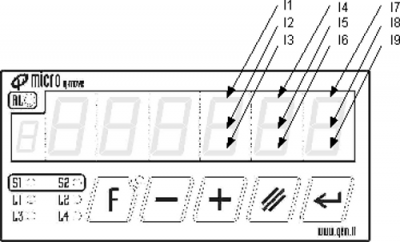
Si voglia creare una visualizzazione che rappresenti lo stato di 9 ingressi digitali. Lo stesso esempio potrà essere poi utilizzato per la rappresentazione di uscite digitali. Assegneremo perciò, ad ogni ingresso, uno dei segmenti di ciascuno dei tre digit più a destra e lo attiveremo quando il corrispondente ingresso sarà attivo.
La figura mostra l'assegnamento scelto per gli ingressi ed i segmenti dei digit del display:
Innanzitutto dichiareremo, nella unit di configurazione, 9 variabili di dimensione FLAG il cui valore simulerà lo stato dei 9 ingressi digitali.
GLOBAL
gfInp01			F
gfInp02			F
gfInp03			F
gfInp04			F
gfInp05			F
gfInp06			F
gfInp07			F
gfInp08			F
gfInp09			F
Dichiareremo poi anche un array global da 8 elementi che servirà per contenere i codici dei caratteri da stampare per ogni combinazione degli ingressi.
ARRGBL
	diagnTab		B	8			;tabella caratteri per diagnostica
Infatti per ogni gruppo di tre ingressi associati ad uno dei tre digit sul display avremo 8 possibili combinazioni. La tabella riassume, ad esempio, per la combinazione degli ingressi I7,I8 ed I9, i possibili lo stati del digit associato:
| I7 | I8 | I9 | Display |
|---|---|---|---|
| 0 | 0 | 0 | |
| 0 | 0 | 1 | |
| 0 | 1 | 0 | - |
| 0 | 1 | 1 | = |
| 1 | 0 | 0 | |
| 1 | 0 | 1 | ~ |
| 1 | 1 | 0 | * |
| 1 | 1 | 1 | $ |
Servirà infine anche la definizione di alcune costanti da utilizzare come maschera per bit generici di un byte:
CONST

;-- Generic bit field mask ---------
B_00            &H01      ; value for bit 00
B_01            &H02      ; value for bit 01
B_02            &H04      ; value for bit 02
B_03            &H08      ; value for bit 03
B_04            &H10      ; value for bit 04
B_05            &H20      ; value for bit 05
B_06            &H40      ; value for bit 06
B_07            &H80      ; value for bit 07
Il codice completo per ottenere la funzione di diagnostica è:
;inizializza tabella
  	diagnTab[1] = CHAR_
  	diagnTab[2] = CHAR_UP
  	diagnTab[3] = CHAR_CENTER
  	diagnTab[4] = CHAR_UPCEN
  	diagnTab[5] = CHAR_LOWER
  	diagnTab[6] = CHAR_LOWUP
  	diagnTab[7] = CHAR_LOWCEN
  	diagnTab[8] = CHAR_LOWUPCE

	;stampa messaggio "INP."
	hmi:dis6 = CHAR_I
	hmi:dis5 = CHAR_N
	hmi:dis4 = CHAR_P ORB CHAR_POINT

MAIN:
  hmi:dis2 = diagnTab[(gfInp01 * B_00 + gfInp02 * B_01 + gfInp03 * B_02) + 1]
  hmi:dis1 = diagnTab[(gfInp04 * B_00 + gfInp05 * B_01 + gfInp06 * B_02) + 1]
  hmi:dis0 = diagnTab[(gfInp07 * B_00 + gfInp08 * B_01 + gfInp09 * B_02) + 1]

  WAIT 1
  JUMP MAIN
END