This is an old revision of the document!
AN008 - Example of using and calibrating the JOINT device
JOINT can be considered a device that combines the functionality of three EANPOS device to control respectively three axes that are called X, Y and Z. Therefore placements are made using a control of P.I.D. type as for the EANPOS device.
The novelty item than the simple single-axis positioner is the ability to make interpolated movements: by this we mean draw arcs precisely to join such as two line segments.
In this section we want to describe the first steps that will make the userin its first approach to the device. You also want to provide a simple example using the JOINT device so that the user has a starting point from which to develop your application.
We can divide in the following sections, the proceed of the operation:
-
device declaration in the configuration unit
-
introduction of parameters in order to correctly calibrate inputs and outputs
-
development of the application according to the needs
Device declaration in the configuration unit
As was already explained in the description of the JOINT device,You must program properly the unit application configuration. It is very important to the part of code that declares the device, here you should indicate the hardware resources to use to ensure proper operation. It will be the responsibility of the programmer to pick and choose the most appropriate inputs and outputs.For example with the following line of code:
;---------------------------------
;  Internal device declaration
;---------------------------------
INTDEVICE
..
<Axis> JOINT 0002 3 20000
                    1.CNT01 1 1.INP01 1.AN01
                    1.CNT02 2 1.INP02 1.AN02
                    2.CNT01 3 2.INP01 2.AN01
                    3.OUT01 3.OUT02 3.OUT03 3.OUT04
You define a JOINT device with name “Asse” were the sampling time is 2 ms. Later he introduced the number of axes that you want to control (3 in this case) and the size of the internal buffer that you use to make the calculations of the interpolation.
This is followed by three rows that are inserted the configuration parameters of the axes (respectively X, Y and Z) as should be done for an EANPOS device. There are: the hardware address of bi-directional meter for the acquisition of the position, the digital address for interruption and a digital address for enable to be used in the homing procedure and finally the address of the analog output for control of the drive connected to the motor you intend to move. This configuration is repeated for the remaining two axes (if you are using 3, otherwise you use currency symbol X or X.Xas usual if you do not use any resource).
Finally you have the ability to declare 4 digital outputs that you can use with this device.
An application that has just inside the device Declaration in the configuration unit and a qcl unit that it does not run anything (excluding the forced WAIT) already allows to perform the first operations using the capabilities of the device. In fact after downloading the application tool and have done work, It can change the parameters,observe the States or give commands to devices using the appropriate monitor from QView.
This is very convenient in the early stages of planning When you just want to make some runs or debugged phase.
Correct device parameterization
 | Note: In this document the various parameters and commands refer to a generic axis, so you have to remember to use parameters and commands related to the axis that you want to control |
|---|
Once declared hardware resources properly to use you need to set some parameters depending on the components that are attached to the Qmove product to properly configure each axis. The operations will be repeated for the three axes. The parameters taken from the EANPOS device have the same name with postponed a letter indicating the axis you are configuring.
Measure and pulse introduction
Let us consider the case the bi-directional transducer is a digital encoder. Suppose that the encoder is directly keyed on an engine that is to move an axis. You will need to set the correctly the measure and pulse parameters so that the latter can interpret the pulses arriving at QMove, the tool will then calculate the position of the axis. The measure and pulse introduction establishes a correspondence between a space in a unit of your choice and a certain number of pulses. In the event that the user already knows the space covered in a round encoder then you'll proceed directly to projecting values.
Let's clarify this concept with an example: If the encoder emits 1000 pulses/Rev and you know that the axis moves about 5 cm when the encoder execute exactly one round then you can insert the following values:
Axis:measurex = 50;
Axis:pulsex = 4000
The measure value introduced it also involves choosing a unit of measure of mm for measuring positions, in the pulse parameter introduces a value equal to the number of encoder impulses multiplied by 4 (the number of fronts generated by the encoder). It is remember that the measure/pulse relationship must be have a value between 0.00935 and 1. It is important to emphasize that the values described above are taken as reference: It is not necessary to introduce the parameters taking as reference a encoder turn as we will describe below.
When the user does not know in advance the measurement parameters, will still be able to make the correct calibration by following these steps:
-
give the command to INIT at device, verify that the st_init status switch to 1
-
through the “monitor device” of QView see on the pc the value of posit parameter
-
sets measure and pulse both to 1 value
-
move the axis manually having him make a move a position easily measurable
-
read the posit value
-
now insert the desired measurement unit the measured value in the measure parameter and the value of the posit parameter in the pulse parameter
The encoder resolution is now correctly set.
A further important operation is set the maxpos and minpos parameters that define respectively the maximum and the minimum position accessible from an axis.
Choice of speed unit measure
The instantaneous speed unit measure of the axis is choice by unitvel and decpt parameters. You can select the unit of time of speed with the unitvel parameter: If this is equal to 0 then the speed is measured in Um/min, if it is equal to 1 then is measured in Um/s. The decpt parameter instead determines whether multiple speed-measuring of the basic measure unit Um. For example, if hte basic measure unit Um=mm, and unitvel=1 you get the speed indicator in the vel variable in:
mm/s (with decpt = 0),
cm/s (with decpt = 1),
dm/s (with decpt = 2),
m/s (with decpt = 3).
Then you need to set the proper display on the terminal operator to adjust the correct decimal point position.
Analogue output calibration
 | Attention: Before executing actual placements verify the connections and mechanic parts. |
|---|
We review the case that your device uses an analogue output implemented with a DAC system: this will assume 16 bit resolution input discrete values (so between -32768 and 32767) to give analog voltage output range ±10V. With the calibration function this analog output can be controlled with a constant value in order to test links and functionality.
Preliminary motion
This section describes the operations to be execute to verify the accuracy of the connections and the functionality of the system.
-
give the INIT command to device, verify that the st_init status switch to 1
-
give the RESUME command to remove a possible emergency condition (st_emrg = 1)
-
enable axis calibration status give the CALON command, the st_cal status switch to 1
-
in these conditions you can set the analog voltage through the vout parameter: the value is expressed in tenths of a Volt (therefore the range of values entered is ±100). It is recommended to introduce low values (5, 10, 15 …)
-
because now the device is used as “voltage generators” the axis should start moving. If this is not the case you should verify the connections. When the axis is moving the frq parameter indicates the frequency of one of the input signals to the bi-directional meter, vel indicates the speed of the axis as posit the position according to the selected unit of measure. If giving positive voltage the position decreases You must reverse the phases of transducer (or moving the cables, or with the CNTREV command) or reverse the direction of the drive
-
if output voltage 0 V you notice that the axis is moving due to offset voltages, these can be compensate using the offset parameter. For an optimal result of the calibration, the operation must be performed with the system in temperature
-
Now you can disable calibration status with the command CALOFF (the st_cal state switch to 0).
Analog output parameterization (setting maxvel parameter)
The device generates the voltage value of the analog output based on a proportion between maximum axis speed and maximum output voltage. To do this you need to set the maxvel parameter, that is the speed at which it moves the axis when maximum voltage is given to the drive. Obviously the axis must have a symmetrical behavior compared to the zero value of analog voltage, so the speed must be the same (in module) To the maximum voltage both positive and negative.
To know the maximum speed there are two ways: the “theoretical method” you should know the maximum speed of the motor (declared maximum laps) from which you can easily obtain the linear speed.
If you do not know the maximum declared speed of the motor you must proceed in this way:
-
enter in the calibration mode (as described above)
-
if possible, provide maximum voltage to the drive and read the value of vel parameter
-
you can also provide a lower voltage and calculate the maximum speed with the proportion vout : 10 V = vel : maxvel
Now you can then enter the value of the maximum speed in the maxvel parameter.
First movement
| Attention: Before moving the axis, check the correct operation of the emergency devices and protection. |
|---|
The procedures described here have allowed to complete the first phase of the device parameterization. Now it is possible to execute a simple movement of the axis. For example, follow these steps:
-
give the INIT command to device, verify that the st_init status switch to 1
-
move the axis to a position for execute a space without bump the limit switches
-
set the parameter that defines the time used by the axis takes to reach the maximum speed from 0 (and vice versa) taccdec=50
-
set the positioning speed with the setvel parameter
-
set the position quota with the setpos parameter
-
set the feedfw parameter to 1000 (100%)
-
reset any emergency status with the RESUME command
-
start positioning with the START command, to stop the movement give the STOP command (or EMRG).
This first movement was performed without activating the ring of space reaction, so any error introduced by offset voltage values or from external agents is not corrected.
Using the RECDATA device to calibrate the PID controller
When the programmer intends to fine tune the parameters of the PID controller, he can use an internal device that allows you to record data of the type: position in primary pulses, Axis Virtual Positions, analog outputs, following error, inputs and outputs states. This tool is called RECDATA and use the RAM of the QMove CPU, therefore, when it is used, The use of the data memory must not exceed the 50% of the total.
The effects of the PID Regulation produce very difficult events to appreciate with the naked eye, the RECDATA device It becomes very useful when you want to calibrate parameters such as pgain, integt or derivt. The events such as overshoot or a slowdown due to excessive value of the integral time must be keep in consideration in the parameterization phase.
Because the RECDATA device use is simple, it's sufficient to declare it in the configuration unit with a line of the type:
;---------------------------------
; Internal device declaration
;---------------------------------
INTDEVICE
Recorder  RECDATA  TCamp  QCTL1  QCTL2  IOutA1  IOutA2  IntL1  IntL2  Ing1  Ing2  Out1  Out2
The device is particularly suitable to monitor the device parameters in fact it allows you to view: The position values in primary pulses (directly taking data from the bidirectional transducer), the theoretical position values that the speed profile generator is producing, the values of an analog output. The user can then notice if the parameters he has entered are correct for his needs.
A more detailed description of the RECDATA device you can find it in the appropriate section, Here we limit ourselves to list the steps to follow to use it:
-
device declaration in the configuration unit entering as inputs and outputs parameters also used by the JOINT device
-
give the STARTR command in the moment that you want to start recording, and STOPR When you want to stop
-
to completed operations from the QView “Monitor” select “Device Panels”, and from there the value for the RECDATA device
-
in the windos that will open are available several options, The most important task to do is give the “Start data acquiring” command
-
on cartesian axes, at the end of loading, will compare the value of the monitored parameters
| Note: The RECDATA device records a significant amount of data inside the RAM of the QMove, at the time of acquisition by the PC the transfer takes place via serial. This operation may be very long due to the low speed of the serial comunication protocol. The user can then take some precautions such as: - Record only those variables that actually need to be monitored - Lower the sampling time of the RECDATA device. |
|---|
Sviluppo di un applicativo per effettuare un posizionamento in interpolazione
Nella sezione precedente è stato spiegato quali sono i primi passi da seguire. Tale esempio impiega solo un ristretto spettro dei parametri impostabili del device, in questa sezione inseriamo un codice di esempio, dettagliatamente commentato, da cui l'utilizzatore può prendere spunto per sviluppare un applicativo.
Il modo in cui il device va dichiarato è spiegato precedentemente, e perciò in questa sezione è omessa la unit di configurazione. Vedi qui.
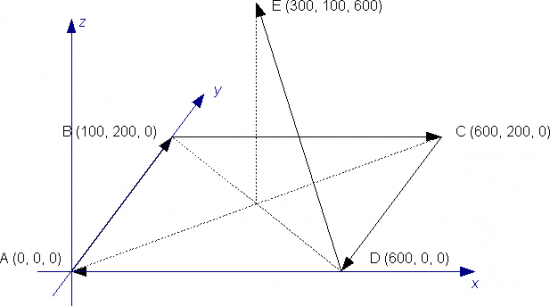
Supponiamo di dovere effettuare dei posizionamenti con interpolazione di tre assi secondo il percorso indicato in figura, analizziamo quale potrebbe essere il codice del programma.
;*************************************************************************************
; Unit di configurazione (sono riportate solo le dichiarazioni di variabili e
; sono omesse le dichiarazioni del bus e del device)
;*************************************************************************************
;---------------------------------------------
;  Definizione Array GLOBAL
;---------------------------------------------
ARRGBL
awPosX    W   5                 ;quote di posizionamento asseX
awPosY    W   5                 ;quote di posizionamento asseY
awPosZ    W   5                 ;quote di posizionamento asseZ
awCodeSt  W   5                 ;codici passo in interpolazione
;-------------------------------------------------------------------------------------
; Definizione Variabili SYSTEM
;-------------------------------------------------------------------------------------
SYSTEM

;-------------------------------------------------------------------------------------
; Definizione Variabili GLOBAL
;-------------------------------------------------------------------------------------
GLOBAL
gbi B

;-------------------------------------------------------------------------------------
; Definizione Variabili INPUT
;-------------------------------------------------------------------------------------
INPUT
ifStart  F 1.INP01

;-------------------------------------------------------------------------------------
; Definizione Variabili OUTPUT
;-------------------------------------------------------------------------------------
OUTPUT


;*************************************************************************************
; Unit qcl
;*************************************************************************************

;************************
; parametrizzazione assi
;************************
;****AsseX****
Asse:measurex = 10000
Asse:pulsex = 40000            ;come calcolare measure e pulse è spiegato nel paragrafo apposito.*
Asse:maxvelx = 100000          ;come calcolare maxvel è spiegato nel paragrafo apposito.*
Asse:mxrlvelx = 15000          ;velocità massima raggiungibile in interpolazione
Asse:maxposx = 1000            ;Quota massima
Asse:minposx = -100            ;Quota minima
Asse:maxfollerrx = 10000       ;Errore di inseguimento massimo
Asse:unitvelx = 0              ;Unità di tempo della velocità (velocità in Um/min)
Asse:decptx = 0                ;Cifre decimali nel calcolo della velocità
Asse:rampmodex = 0             ;Tipo di rampe utilizzate (in questo caso stesso tempo di accelerazione
                               ;o decelerazione da velocità zero a velocità massima)
Asse:taccdecx = 100            ;Tempo di accelerazione e di decelerazione (durante movimenti non interpolati)
Asse:tinvx = 0                 ;Tempo di inversione asse
Asse:tollx = 5                 ;Tolleranza (impostata in Um)
Asse:toldlyx = 10              ;Tempo di ritardo attivazione stato di tolleranza
Asse:offsetx = 0               ;Tensione di offset
Asse:pgainx = 10               ;Guadagno proporzionale
Asse:feedfwx = 1000            ;Feedforward
Asse:integtx = 0               ;Tempo integrale
Asse:derivtx = 0               ;Tempo derivativo

;****AsseY****
Asse:measurey = 10000
Asse:pulsey = 40000            ;come calcolare measure e pulse è spiegato nel paragrafo apposito.*
Asse:maxvely = 100000          ;come calcolare maxvel è spiegato nel paragrafo apposito.*
Asse:mxrlvely = 15000          ;velocità massima raggiungibile in interpolazione
Asse:maxposy = 1000            ;Quota massima
Asse:minposy = -100            ;Quota minima
Asse:maxfollerry = 10000       ;Errore di inseguimento massimo
Asse:unitvely = 0              ;Unità di tempo della velocità (velocità in Um/min)
Asse:decpty = 0                ;Cifre decimali nel calcolo della velocità
Asse:rampmodey = 0             ;Tipo di rampe utilizzate (in questo caso stesso tempo di accelerazione
                               ;o decelerazione da velocità zero a velocità massima)
Asse:taccdecy = 100            ;Tempo di accelerazione e di decelerazione (durante movimenti non interpolati)
Asse:tinvy = 0                 ;Tempo di inversione asse
Asse:tolly = 5                 ;Tolleranza (impostata in Um)
Asse:toldlyy = 10               ;Tempo di ritardo attivazione stato di tolleranza
Asse:offsety = 0               ;Tensione di offset
Asse:pgainy = 10               ;Guadagno proporzionale
Asse:feedfwy = 1000            ;Feedforward
Asse:integty = 0               ;Tempo integrale
Asse:derivty = 0               ;Tempo derivativo

;****AsseZ****
Asse:measurez = 10000
Asse:pulsez = 40000            ;come calcolare measure e pulse è spiegato nel paragrafo apposito.*
Asse:maxvelz = 100000          ;come calcolare maxvel è spiegato nel paragrafo apposito.*
Asse:mxrlvelz = 15000          ;velocità massima raggiungibile in interpolazione
Asse:maxposz = 1000            ;Quota massima
Asse:minposz = -100            ;Quota minima
Asse:maxfollerrz = 10000       ;Errore di inseguimento massimo
Asse:unitvelz = 0              ;Unità di tempo della velocità (velocità in Um/min)
Asse:decptz = 0                ;Cifre decimali nel calcolo della velocità
Asse:rampmodez = 0             ;Tipo di rampe utilizzate (in questo caso stesso tempo di accelerazione
                               ;o decelerazione da velocità zero a velocità massima)
Asse:taccdecz = 100            ;Tempo di accelerazione e di decelerazione (durante movimenti non interpolati)
Asse:tinvz = 0                 ;Tempo di inversione asse
Asse:tollz = 5                 ;Tolleranza (impostata in Um)
Asse:toldlyz = 10              ;Tempo di ritardo attivazione stato di tolleranza
Asse:offsetz = 0               ;Tensione di offset
Asse:pgainz = 10               ;Guadagno proporzionale
Asse:feedfwz = 1000            ;Feedforward
Asse:integtz = 0               ;Tempo integrale
Asse:derivtz = 0               ;Tempo derivativo

;****Parametri device****
Asse:setveli = 10000           ;Velocità in interpolazione
Asse:maxveli = 15000           ;Velocità massima in interpolazione
Asse:tacci = 100               ;Tempo di accelerazione di interpolazione
Asse:prgmode = 0               ;impostazione delle quote come assolute


;****Inizializzazione del device****
INIT Asse                     ;Inizializza il device
WAIT Asse:st_init             ;Attendi che il device sia inizializzato
CNTUNLOCKX Asse               ;Sblocca acquisizione posizione asse X
WAIT NOT Asse:st_cntlockx     ;Attendi che l'acquisizione della posizione sia sbloccato
CNTUNLOCKY Asse               ;Sblocca acquisizione posizione asse Y
WAIT NOT Asse:st_cntlocky     ;Attendi che l'acquisizione della posizione sia sbloccato
CNTUNLOCKZ Asse               ;Sblocca acquisizione posizione asse Z
WAIT NOT Asse:st_cntlockz     ;Attendi che l'acquisizione della posizione sia sbloccato
CNTDIRX Asse                  ;Imposta il senso dell'acquisizione di posizione asse X
WAIT NOT Asse:st_cntrevx      ;Attendi che sia impostato il senso dell'acquisizione di posizione
CNTDIRY Asse                  ;Imposta il senso dell'acquisizione di posizione asse Y
WAIT NOT Asse:st_cntrevy      ;Attendi che sia impostato il senso dell'acquisizione di posizione
CNTDIRZ Asse                  ;Imposta il senso dell'acquisizione di posizione asse Z
WAIT NOT Asse:st_cntrevz      ;Attendi che sia impostato il senso dell'acquisizione di posizione
REGONX Asse                   ;Abilita la regolazione asse X
WAIT NOT Asse:st_regoffx      ;Attendi l'abilitazione alla regolazione
REGONY Asse                   ;Abilita la regolazione asse Y
WAIT NOT Asse:st_regoffx      ;Attendi l'abilitazione alla regolazione
REGONZ Asse                   ;Abilita la regolazione asse Z
WAIT NOT Asse:st_regoffx      ;Attendi l'abilitazione alla regolazione
RESUMEX Asse                  ;Togli l'asse x da eventuale stato di emergenza
WAIT NOT Asse:st_emrgx        ;Attendi che l'asse non sia in emergenza
RESUMEY Asse                  ;Togli l'asse y da eventuale stato di emergenza
WAIT NOT Asse:st_emrgx        ;Attendi che l'asse non sia in emergenza
RESUMEZ Asse                  ;Togli l'asse z da eventuale stato di emergenza
WAIT NOT Asse:st_emrgx        ;Attendi che l'asse non sia in emergenza
LOOPONX Asse                  ;Aggancia loop di reazione dell'asse x
WAIT Asse:st_looponx          ;Attendi che sia agganciato il loop di reazione dell'asse
LOOPONY Asse                  ;Aggancia loop di reazione dell'asse y
WAIT Asse:st_looponx          ;Attendi che sia agganciato il loop di reazione dell'asse
LOOPONZ Asse                  ;Aggancia loop di reazione dell'asse z
WAIT Asse:st_looponx          ;Attendi che sia agganciato il loop di reazione dell'asse

;***********************************************
; impostazione del programma di posizionamenti
;***********************************************
;coordinate asse X
awPosX[1] = 0
awPosX[2] = 100
awPosX[3] = 600
awPosX[4] = 500
awPosX[5] = 300

;coordinate asse Y
awPosY[1] = 0
awPosY[2] = 200
awPosY[3] = 200
awPosY[4] = 0
awPosY[5] = 100

;coordinate asse Z
awPosZ[1] = 0
awPosZ[2] = 0
awPosZ[3] = 0
awPosZ[4] = 0
awPosZ[5] = 600

;codici passo in intepolazione
awCodeSt[1] = 0
awCodeSt[1] = 0
awCodeSt[1] = 0
awCodeSt[1] = 3000        ;attesa di 1 secondo dopo il 4 posizionamento
awCodeSt[1] = 10001       ;accensione dell'uscita 1 al termine dell'ultimo posizionamento

;*************************************
; scrittura dei passi nel programma
;*************************************
Asse:stepnum = 1          ;memorizzo una coordinata alla volta
FOR (gbi=1, gbi LE 5, 1)
  Asse:stepin = gbi
  Asse:codex1 = awPosX[gbi]     ;coordinata asse X
  Asse:codey1 = awPosY[gbi]     ;coordinata asse Y
  Asse:codez1 = awPosZ[gbi]     ;coordinata asse Z
  Asse:codestp1 = awCodeSt[gbi] ;codice passo in interpolazione
  Asse:stepout = 0
  WRITESTEP Asse
  WAIT Asse:stepout EQ Asse:stepin
NEXT

;ora è completa la tabella del programma dei posizionamenti

Asse:stepbeg = 1      ;passo di inizio programma
Asse:stepend = 5      ;passo di fine programma
Asse:setveli = 8000   ;velocità di interpolazione

MAIN:
IF ifStart        ;se do il comando di start da ingresso digitale
  STARTPRG Asse
ENDIF
Come calcolare measure e pulse è spiegato nel paragrafo apposito.
Per effettuare dei posizionamenti semplici le operazioni da svolgere sono le stesse che sono state analizzate nella descrizione del device EANPOS.