This is an old revision of the document!
DEVICE CAMMING3
0.1 Introduction
The camming, is a technique applicable to motion control servo axes and allows you to solve applications where one or more slave axes have spaces, uneven, too staying in sync with respect to the position of a reference axis called “master”. The master axis can be a real or virtual axis (the master simulated).
Typical applications are:
-
Cuts and processes on the fly, both linear and circular, on plastic, sheet metal, cardboard.
-
Packaging in place of mechanical cams.
-
In the winding of cable, wire, etc. with wiring-guide.
-
In textiles and in feeding the “grinding machine” for layering of fabrics or pasta.
-
In screen printing or flexo printing plates.
-
In the lines of “transport product” for spacing and/or synchronization of the materials movement.
The absolute position that must assume the slave axis is always expressed as a function of position absolute master axis and this Association is placed in a specific table called “cam table”.
The “cam table” consists of 128 sectors; each sector consists of:
CodeG = operating instruction of the sector in use.
CodeQm = incremental position of the master, in units; are accepted only positive increments.
CodeQs = incremental position of the slave, in units; both positive and negative increments are accepted.
CodeM = general numeric code that can be used by the PLC logic.
CodeQma = special operating instructions auxiliary master quota used.
CodeQsa = special operating instructions auxiliary slave used quota.
The codeG operative instructions associated with each sector of the cam, you can be defined how motion law (acceleration, deceleration, constant speed…) the slave axis must move along the space established in codeQs at the same time as the master runs through the space defined as codeQm.
Until the master is moving at constant velocity, the space covered by the master axis is directly proportional to the time spent and the codeQs e codeQm spaces being always defined in the same amount of time even the law of motion applied to the slave axis, within the sector, is applicable in direct proportion to the space covered by the master in the sector; the master and the slave are therefore linked in space between them.
If the speed constant chosen for the master is the maximum you can evaluate immediately what the maximum accelerations, decelerations and speeds that will be the slave axis.
This procedure allows you to formulate the law of motion of the slave axis as a function of time to evaluate the dynamic performance required by your application and then apply the the same law of motion as a function of space covered by the master during the execution of the cam.
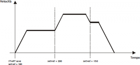
To simplify the calculation of the absolute positions of the master and the slave It is assumed that the master is moving at a constant speed whereby the axes positions can be represented in a Cartesian diagram Speed / Time. Below is a simple example of compiling the “cam table”.
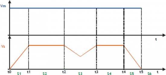
In order to can run a cam as in the example, you have to fill in the “cam table” as follows:
| Sector | CodeG | CodeQm | CodeQs | |
|---|---|---|---|---|
| S1 | 132 | 100 | 50 | Acceleration sector with Vs = Vm at the end of the sector |
| S2 | 133 | 200 | 200 | Intermediate sector at constant speed |
| S3 | 134 | 160 | 120 | Compensation sector with initial velocity = final velocity |
| S4 | 133 | 150 | 150 | Intermediate sector at constant speed |
| S5 | 135 | 90 | 45 | Deceleration sector with Vs = 0 at the end of the sector |
| S6 | 136 | - | - | Finish command cam |
QEM is available to help customers in the of the “cam table” compilation.
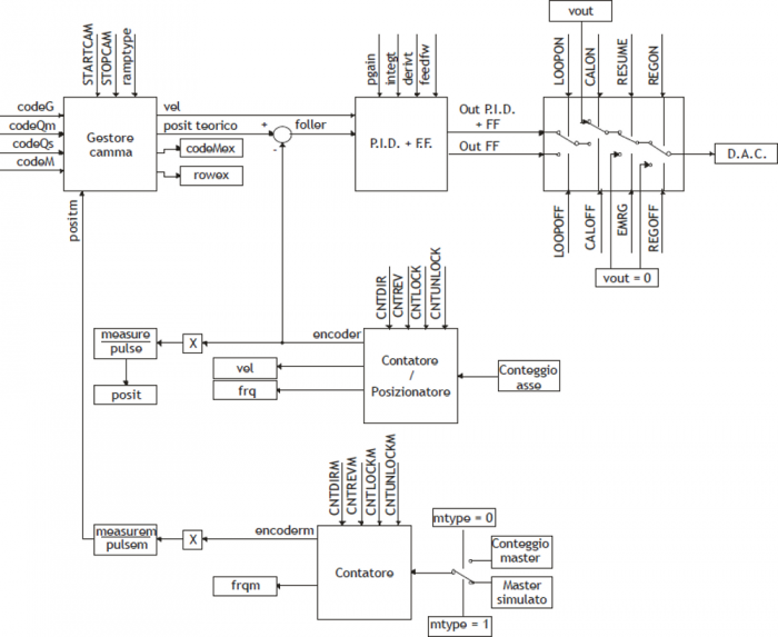
The device can be divided into two main parts:
A slave axis positioner with trapezoidal or selectable planetary ramps.
Analog cam generator.
Basic block diagram is as follows:
0.2 Installation
0.2.1 Device declaration in the configuration file (.CNF)
In the configuration file (.CNF), the BUS section must be declared so that they are present the hardware resources required for the implementation of the device CAMMING3. There must be at least two bidirectional counter and a 16-bit resolution analog output. In the INTDEVICE section of the .CNF file must be to add the following definition:
;-------------------------------
; Internal device declaration
;-------------------------------
INTDEVICE

<nome_device>  CAMMING3  TCamp  CountS  CountMA  CountMB  IntL  IAZero IntLM  IAZeroM  InG  InGInt  IoutA  Out
 | It is necessary that each definition appears on the same line and in the same sequence. The resources for the device that are not used must be indicated by a red X in place of their physical address. |
|---|
Where:
| INTDEVICE | Is a keyword indicating the beginning of the definition of internal device. |
| device_name | Is the device name. |
| CAMMING2 | Is the keyword that identifies the device described in this document. |
| TCamp | Sample time device (1÷250 ms). |
| CountS | Bidirectional counter Slave address |
| CountMA | Bidirectional counter Master address “A” |
| CountMB | Bidirectional counter Master address “B” |
| IntL | Number of the interrupt line dedicated to the encoder zero pulse Slave during the activity phase of presets. Allowed values: 1÷8 (to prevent the device uses this resource, Enter the X character). |
| IAZero | Slave zero pulse enable input (to prevent the device uses this resource, Enter the X.X character) |
| IntLM | Number of the interrupt line dedicated to the Master encoder zero pulse during the research phase of presets. Allowed values: 1÷8 (to prevent the device uses this resource, Enter the X character). |
| IAZeroM | Enable input zero-pulse master (to prevent the device uses this resource, Enter the X.X character) |
| InG | Entry for generic function as described in the section of the table input configuration (to prevent the device uses this resource, Enter the X.X character) |
| InGInt | Number of the interrupt line dedicated to a generic function as described in the section of the table input configuration. Allowed values: 1÷8 (to prevent the device uses this resource, Enter the X character). |
| IoutA | Hardware address of the DAC from analog output Slave. |
| Out | Output for generic function as described in section output configuration table (to prevent the device uses this resource, Enter the X.X character) |
0.2.1.1 Example
;---------------------------------
; Internal device declaration
;---------------------------------
INTDEVICE
AxisX  CAMMING3  2  2.CNT01  2.CNT02  1.CNT01  1  2.INP01  2  2.INP02  2.INP03  5  2.AN01  2.OUT01
0.2.1.1.1 Application example
You take as an example a CAMMING2 device configured as in the START-UP and with parameterisation of the axis (set-up) already written.
The task is first initialized the device and then run a interrupt input which shows its status on an exit.
The task will be carried out:
;-------------------------------------
; CAMMING3 device management
;-------------------------------------
INIT AxisX                      : Initializes the axis
WAIT AxisX:st_init              ; Wait until the axle is initialized
LOOPON AxisX                    ; Hooks the control loops
WAIT AxisX:st_loopon            ; Wait for the axis has hooked the
                                ; control loops
CALOFF AxisX                    ; Exit from calibration
                                ; of the axis
WAIT NOT AxisX:st_cal           ; Wait until the device is not in
                                ; calibration
CNTUNLOCK AxisX                 ; Unlocks the master counter
WAIT NOT AxisX:st_cntlock       ; Wait until the counter master is
                                ; unlocked
CNTDIR AxisX                    ; Sets the right direction of increase
                                ; slave counter
WAIT NOT AxisX:st_cntrev        ; Wait until the slave counter is
                                ; set in the sense of increase
CNTUNLOCKM AxisX                ; Unlocks the master counter
WAIT NOT AxisX:st_cntlockm      ; Wait until the counter master is
                                ; unlocked
CNTDIRM AxisX                   ; Sets the right direction master
                                ; counter increment
WAIT NOT AxisX:st_cntrevm       ; Wait until the counter master is
                                ; set in the sense of increase
REGON AxisX                     ; Unlock the adjusting
WAIT NOT AxisX:st_regoff        ; Wait for the regulation unlocking

MAIN:

IF AxisX:st_int                 ; If the interrupt line is active
  AxisX:funOut = 2              ; activates output
ELSE
  AxisX:funOut = 1              ; disables the output
ENDIF

ENDIF                           ; END

WAIT 1
JUMP MAIN
END
0.2.1.2 Calcolo della risoluzione
The CAMMING3 device lets the installer can work with unfinished encoder resolutions by setting the data as space covered in a round encoder (measure) and number of pulses/Rev encoder (pulse).
The relationship between the measure and pulse is the encoder resolution and must have values between 1 and 0.000935.
0.2.1.2.1 Definitions:
1) The measure paramenter is placed in units without decimal points (for example 100.0 millimeters is inserted 1000 tenths of a millimeter).
2) The pulse parameter is inserted 4 encoder bitrate (for example if connected an encoder with 1024 pulses round, is inserted 4096, If the measure is calculated on a encoder round).
0.2.1.2.2 Example:
You have to control a rotating table that have the accuracy of 0,1° with the 1024 pulses round encoder mounted directly to the motor; you will set the following values:
measure = 3600
pulse = 4096
0.2.1.3 Decimal point
If for the selected unit of measure is also provided for the presence of a decimal point positions must be represented as an integer and represent space on the drive measurement without decimal point. The resolution must be calculated using the same method and in the parameter measure the magnitude without decimal point. The decimal point will then be inserted into the representation of the value-time viewers (ex. as properties in the HMI). This parameter can take 0÷3 values.
0.2.1.4 Speed
The speeds are always expressed in whole units of measure in the unit of time choice. From this it emerges that the device must know the location of the decimal point of the unit of measure and this is done with the decpt parameter.
0.2.1.5 Main controls
This section describes only the use of a number of some commands; for descriptions of all the set commands, refer to the following chapters.
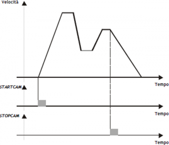
The two main controls are what give start and break execution of cam: STARTCAM and STOPCAM. There are also a series of commands dedicated to emergency response, the loop control, START and STOP the axis.
STARTCAM
The STARTCAM command, the slave axis attaches to master and will follow the trend described in the cam always starting from the first sector. You cannot take a STARTCAM during the execution of the (st_camex = 1) cam; ihis control is left to the programmer.
The cam will pop out automatically if it encounters a END instruction or you can stop it in flight by using the STOPCAM.
0.2.1.5.1 STOPCAM
If the cam is running (st_camex = 1), Once received the STOPCAM command the slave axis is released immediately by the master, brings his speed to zero following the deceleration ramp set (tdec parameter) and remaining in reaction to space. The deceleration ramp is asynchronous with respect to the master.
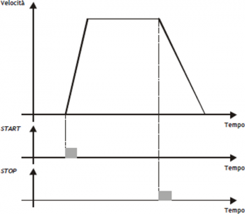
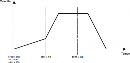
0.2.1.5.2 START
At the START command, the slave axis is positioned to the dimension declared in the setpos variable with the speed set in setvel; the placement will run using the acceleration ramp set in tacc parameter and the deceleration ramp set in parameter tdec. The type of ramp used (trapezoidal or epicycloidal) is inserted in the ramptype parameter.
0.2.1.5.3 STOP
If during the placement (not during the execution of a cam) you must stop the axis with a deceleration ramp, It will simply give the STOP command the axis decelerates to a stop with the ramp in the tdec parameter.
0.2.1.6 Change speed and moving ramp time
When positioning it is possible to vary the speed of the axis without affecting the location to get to. This can lead to an increase or a decrease in velocity, even in several places of the same positioning. This is accomplished with new writing in the setvel parameter. No gear is always available except during the deceleration ramp and is reported (st_chvel = 1)
When positioning can be varied even acceleration/deceleration times. For example, the device can start a placement at a rate very short and once they reach the speed set, varied tacc parameter and executed a change of speed with a very long ramp.
For special applications and trapezoidal ramps, ramp time can be varied even during a change of speed, in this case the new time is put into execution immediately.
0.2.1.6.1 EMRG
This command puts the axis in emergency conditions; the st_emrg state is set to one. If the emergency command is sent to the axis during a placement, movement is stopped without deceleration ramp, the analog output will be set to zero volts and you dropped the reaction of space. If the cam is active (st_camex = 1), the movement is interrupted without deceleration ramp, the analog output will be set to zero volts, space reaction is released and the cam (st_camex = 0).
With st_emrg = 1 (emergency condition), you cannot move the axis.
0.2.1.6.2 RESUME
This command will reset the emergency condition; the axis comes in reaction to space and waits for a command to be able to move (does not automatically resume interrupted positioning).
0.2.1.6.3 LOOPOFF
The LOOPOFF command removes the reaction of space without stopping the axis. With st_loopon = 0 the axis handling axis commands but accepts all placements will be performed without reaction of space. A placement made reaction loop-free is comparable to a positioning run without proportional gain (is not guaranteed to arrive in position).
0.2.1.6.4 LOOPON
The LOOPON command closes the ring of space without stopping the axis. With st_loopon = 1 the axis is moved using the P.I.D. control features.
Following is a table summarizing the conditions necessary for the axis in reaction to space and to perform placements.
| Loopon | Emrg | Space reaction | Possibility of movement |
|---|---|---|---|
| YES | NO | YES | YES |
| YES | YES | NO | NO |
| NO | NO | NO | YES |
| NO | YES | NO | NO |
0.2.1.7 Description of epicycloidal motion
The epicycloidal motion is used to move the axes without sudden variations of speed. The time of positioning of an axis moved by trapezoidal ramps is the same compared to the same axis moved by epicycloidal ramps, but ramps vary the shear rate (acceleration) with up to half of the ramp itself.
For comparison shows the difference of the development of the acceleration in the two cases: with linear ramp (trapezoidal) and with ramp reducers.
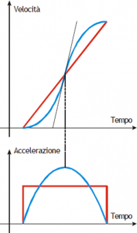
The same goes for the deceleration ramp.
Epicycloidal movement has the ability to behave in different ways in the event of a reduction in profile (rtype) and in the case of stop during acceleration (stopt) If the cam is not running (st_camex = 0).
0.2.1.8 Profile reduction
| The profile reduction is used only if you are doing a placement and not if you're running a cam (st_camex = 0). |
|---|
If the cam is not running (st_camex = 0) and space to go is less than that which allows to reach the speed set by the acceleration and deceleration ramps, you pass in the phase called “profile reduction”.
You can keep fixed the time of ramps, decreasing gradients of the ramps and the speed in proportion (rtype parameter set to 0).
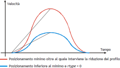
You can also decrease the time of the ramps while maintaining the gradient of constant acceleration and decrease speed in proportion (rtype parameter set to 1).
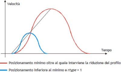
With the rtype parameter set to 0 xtend considerably the time needed to placements with loss of productivity of the machine, instead of setting it to 1 in case of short placements shorter, but keeping the constant gradient you lose the beneficial effect of the epicycloidal action.
0.2.1.9 Type of stop during acceleration ramp
| The type of stop while the ramps is only used if you are doing a placement and not if you're running a cam (st_camex = 0). |
|---|
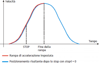
In the event that the cam is not running (st_camex = 0) and we should curb the axis during acceleration with STOP commnand You must choose whether to complete the flight, or if you want to abort the flight and consequently change the epicycloidal action.
In case you set the stopt parameter to 0 is first completed the acceleration ramp and then performed the deceleration ramp.
In case you set the parameter stopt to 1 stops the acceleration ramp and started immediately the deceleration ramp set.
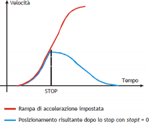
You immediately notice that there is a substantial difference between the setting of stopt to 0 or to 1.
To make the choice of what type of stop use, one must remember that in case of emergency stop the emergency command exists that instantly locks and without ramp positioning.
0.2.1.10 Analogue output calibration
| Before starting actual placements you must make sure that electrical connections and mechanical appliances have not cause malfunctions. |
|---|
For the management of the axis, the device uses a ± 10 V analogue output range and 16-bit signed resolution; this calibration function with analog output can be driven with a constant value in order to test links and functionality.
0.2.1.10.1 Preliminary motion
-
Remove the emergency condition with the RESUME command.
-
The state st_emrg = 0
-
Enable calibration axis status with the CALON command; the st_cal state must therefore be 1.
-
You can now set the analog voltage with the vout parameter; the value is expressed in tenths of volt (-100 ÷ 100 = -10 ÷ 10 V). It is recommended to introduce low values (5, 10, 15… equal to 0.5, 1, 1,5 V).
-
When the axis is moving the frq parameter indicates the frequency in Hz of the sphases of the transducer.
-
The posit parameter that displays the position varies indicating the space covered by the axis. If setting a positive voltage will count decrements, it is necessary to invert the phases of the transducer or reverse the direction in driving.
-
You can reverse the direction of the count using the CNTREV command.
-
If with output voltage to zero the axis is not stationary, adjust the offset parameter to correct the voltage until movement does not stop. The input value (each bit corresponds to 0.3 mV), will be added algebraically to the value of the analogue output; This operation allows to compensate for any drift of electronic component, both in QMOVE outgoing and to driver input. The value is expressed in bits with sign.
For an optimal result of calibration this operation must be performed with the system to temperature capacity. -
To disable calibration status send the CALOFF command.
-
The state st_cal = 0
0.2.1.10.2 Output setting
The device generates the voltage value of the analogue output based on a ratio between the maximum velocity of the axis and the maximum output voltage. Proportionality is obtained with the maxvel parameter, that represents the speed of the axis on the analog voltage (10 V). Obviously the axle must behave symmetrical analog voltage to zero, therefore the speed must be the same on both the positive and negative voltage at maximum.
Prior to determining the value of maximum velocity,we must establish the unit of time to use for the representation of the speed in the device; the unitvel parameter defines the unit of time of speed (Um/min or Um/s).
0.2.1.10.3 Metodo teorico per la determinazione della velocità massima
The theoretical method is a calculation that was performed on the basis of maximum motor speed. Once established the maximum revolutions per minute that are declared in the motor, We get the maximum velocity is expressed in the unit of measure the unit of time chosen. Enter the maximum velocity value calculated in the maxvel parameter.
0.2.1.10.4 Practical method for determining the maximum speed
The practical approach is based on the reading of the speed detected by the device in the vel parameter, giving the drive a known voltage. To provide the voltage to drive the device should be placed in a position of calibration as described in the previous paragraph. If the system permits, give the drive a voltage of 10 V and read the speed value in the vel parameter. If, on the other hand, provides a part of the output voltage (1, 2, … 5 V), calculate the maximum velocity with a proportion.
Enter the value found by maximum velocity in the maxvel parameter.
0.2.1.11 Movement
| Before handling the Board, check the proper operation of emergency equipment and protection. |
|---|
The procedures described here have allowed us to complete the first phase of parameterizing device. Now you can run simple movement of the axis.
-
Move the axis in a position whereby it can fulfill a certain area without touching the maximum and minimum quota limits.
-
Set the current position to zero axis, by setting the parameter posit = 0.
-
Set up the parameters that define the position of the limit switches software: minpos = 0 and maxpos the value of the maximum stroke of the axis.
-
Set the parameter that defines the axis time to reach the maximum speed tacc = 100. This parameter is expressed in hundredths of a second (100 = 1 sec.)
-
Set the speed of positioning with the setvel parameter.
-
Set the target quota with the setpos parameter.
-
Set the parameter feedfw = 1000 (100%)
-
If the device is in emergency state (st_emrg = 1) give the RESUME command.
-
Start positioning with the START command. To stop the movement give the EMRG command.
This first movement was done without speed feedback space. The placement may have been executed with some error introduced by the non-linearity of the components or an imperfection in the calibration of the maximum speed. Enabling space feedback this error goes away.
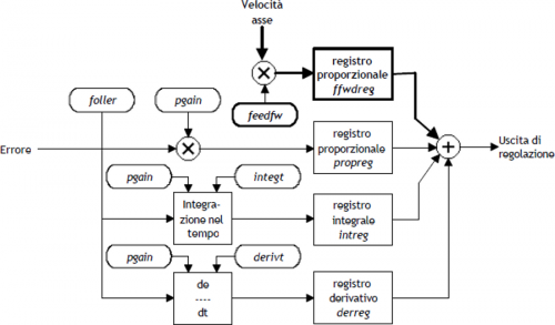
0.2.1.12 PID+FF Calibration
The placement runs in the preceding paragraph has been made without considering any position errors.
To check the correct position of the axis in continuously and automatically, You must have the position feed-back; for this reason introduces the control algorithm PID + FF including proportional shares, integral, derivative and feed-forward; the value of the analog output is given by the summation of feed forward, proportional, derivative and integrative actions.
This section describes a series of actions to adjust the parameters that affect this control.
In order to achieve a satisfactory adjustment is sufficient to use only the actions feedforward and proportional; integral and derivative actions are used only for adjustments under special conditions.
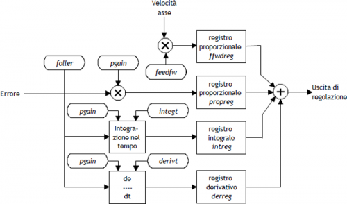
0.2.1.12.1 Feed forward action
The feed-forward helps make the system more ready on placements, providing the analogue output voltage proportional to the theoretical speed of positioning. In practice it is the component which you performed the placements of the previous chapter.
The contribution of this action can be adjusted with the parameter feedfw; This parameter is expressed as 1/1000 speed theoretical portion; so, to introduce such as 98.5% you must set 985 (thousandths).
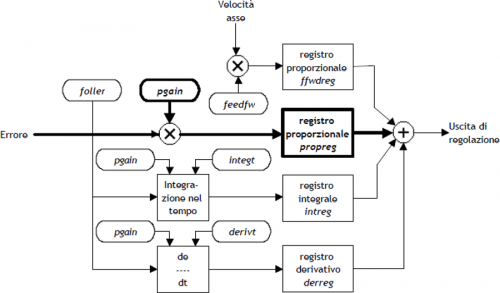
0.2.1.12.2 Proportional action
This action provides an output proportional to the instantaneous axis position error. The extent of the proportional action is defined by the pgain parameter that defines the sensitivity of the system.
The pgain parameter is introduced in thousandths; the unit value of the gain (1000) provides an analog output to maximum value (10 V) concerning the maximum speed error. For maximum speed error means the space taken by axis - at the maximum speed - for the duration of the sampling time of the device.
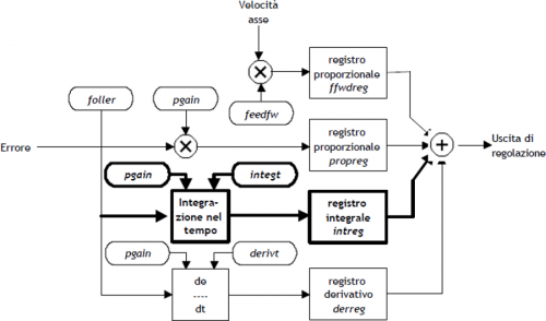
0.2.1.12.3 Integral action
Integrates the position error of the system over time set in integt parameter updating the release until the error is not canceled. If it drops the integration time of the error, the system retrieves the error faster, but can become unstable, tending to swing.
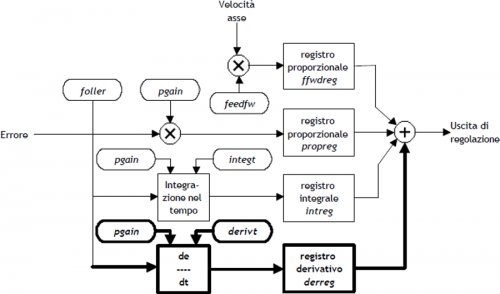
0.2.1.12.4 Derivative action
Anticipates the change of the motion of the system by delete the overshoot positioning. The size of change is calculated over time set in derivt parameter. When the time of derivation of error is higher, more faster is the transient error recovery system, but if you enter a value that is too high the system becomes unstable, tending to fluctuate.
0.2.1.13 Movement application
In order to move the slave axis must first declare the parameterization of axis. Once this stage is thought to want to move the slave axis with jog manuals using Inp01 input for moving forward and the Inp02 input to move it back.
As an example, consider a device configured as in START UP. The task is first initialized the device and then run the manual jog.
;----------------------------------------------------
; Manual jog management
;----------------------------------------------------

INIT AxisX                          : Initializes the axis
WAIT AxisX:st_init                  ; Wait until the axle is initialized
LOOPON AxisX                        ; Hooks the control loops
WAIT AxisX:st_loopon                ; Wait for the axis has hooked the
                                    ; control loops
CALOFF AxisX                        ; Exit from calibration
                                    ; of the axis
WAIT NOT AxisX:st_cal               ; Wait until the device is not in
                                    ; calibration
CNTUNLOCK AxisX                     ; Unlocks the master counter
WAIT NOT Axis:st_cntlock            ; Wait until the counter master is
                                    ; unlocked
CNTDIR AxisX                        ; Sets the right direction of increase of
                                    ; slave counter
WAIT NOT AxisX:st_cntrev            ; Wait until the counter is slave
                                    ; set in the sense of increase
CNTUNLOCKM AxisX                    ; Unlocks the master counter
WAIT NOT AxisX:st_cntlockm          ; Wait until the counter master is
                                    ; unlocked
CNTDIRM AxisX                       ; Sets the right direction of increase of
                                    ; master counter
WAIT NOT AxisX:st_cntrevm           ; Wait until the counter master is
                                    ; set in the sense of increase
REGON AxisX                         ; Unlock the adjusting
WAIT NOT AxisX:st_regoff            ; Wait the unlocked of the regulation
MAIN:

IF Inp01 AND Inp02                  ; If the Inp01 and the
                                    ; Inp02 inputs are active
  IF NOT AxisX:st_still             ; If the axis is not stationary
    STOP AxisX                      ; Stop the axis
  ENDIF
ENDIF

IF Inp01 AND NOT Inp02              ; I the Inp01 input is
                                    ; active and the
                                    ; Inp02 input are deactivate
  IF AxisX:st_still                 ; If the axis is stopped
    AxisX:setvel=AxisX:maxvel/10    ; I set the speed of
                                    ; manual movement
    MANFW AxisX                     ; Forward manual
  ENDIF
ELSE
  IF NOT Inp02                      ; If the Inp02 input
                                    ; is deactive
    IF NOT AxisX:st_still           ; If the axis is not stationary
       STOP AxisX                   ; Stop the axis
    ENDIF
  ENDIF
ENDIF

IF Inp02 AND NOT Inp01              ; If the Inp02 input
                                    ; is active and the Inp01
                                    ; input is deactivate
  IF AxisX:st_still                 ; If the axis is stopped
    AxisX:setvel=AxisX:maxvel/10    ; I set the speed of
                                    ; manual movement
    MANBW AxisX                     ; Backward manual
  ENDIF
ELSE                                ; Otherwise
  IF NOT Inp01                      ; If the Inp01 input is
                                    ; deactive
  IF NOT AxisX:st_still             ; If the axis is not stationary
     STOP AxisX                     ; Stop the axis
  ENDIF
ENDIF                               ; END

WAIT 1
JUMP MAIN
END
0.2.1.14 The sector structure
The device does not have inside datagroup or array data where you can contain various types of cams, so, if you need to manage different cams according to the type of work, you must place the CPU tools and download data on the device whenever there is a need.
Example:
This example handles the cam programming with data entered in the second program of a datagroup. The device is configured as described in the startup.
;--------------------------------------------------
; Configuration file
;--------------------------------------------------

;--------------------------------------------------
; Global Variables
;--------------------------------------------------

GLOBAL
gfProgram F ;Enabling cam programming

;--------------------------------------------------
; System Variables
;--------------------------------------------------

SYSTEM
sbPuntProg B ;Program number that you want to put into execution

;--------------------------------------------------
; Datagroup Variables
;--------------------------------------------------

DATAGROUP
dgCamma

DATAPROGRAM 10 ;10 available programs
ddlCode L ;program code

STEP 128 ;128 available program step
ddbCodeG B ;G code
ddlCodeQs L ;Qs code
ddlCodeQs L ;Qm code
ddlCodeM L ;M code
ddlCodeQma L ;auxiliary Qm code
ddlCodeQsa L ;auxiliary Qs code

;--------------------------------------------------
; Cam programming tasks
;--------------------------------------------------
MAIN:
   .
   .
   sbPuntProg = 2 ;Setting the program pointer
   .
   .

;--------------------------------------------------
; Programming of the CAMMING2 device
;--------------------------------------------------
IF gfProgram
   AxisX:codeG1     = ddbCodeG [sbPuntProg , 1] ;Sector 1
   AxisX:codeQm1    = ddlCodeQm [sbPuntProg , 1] ;Sector 1
   AxisX:codeQs1    = ddlCodeQs [sbPuntProg , 1] ;Sector 1
   AxisX:codeQma1   = ddlCodeQma [sbPuntProg , 1] ;Sector 1
   AxisX:codeQsa1   = ddlCodeQsa [sbPuntProg , 1] ;Sector 1
   AxisX:codeM1     = ddlCodeM [sbPuntProg , 1] ;Sector 1
   AxisX:codeG2     = ddbCodeG [sbPuntProg , 2] ;Sector 2
   AxisX:codeQm2    = ddlCodeQm [sbPuntProg , 2] ;Sector 2
   AxisX:codeQs2    = ddlCodeQs [sbPuntProg , 2] ;Sector 2
   AxisX:codeQma2   = ddlCodeQma [sbPuntProg , 2] ;Sector 2
   AxisX:codeQsa2   = ddlCodeQsa [sbPuntProg , 2] ;Sector 2
   AxisX:codeM2     = ddlCodeM [sbPuntProg , 2] ;Sector 2

   .
   .

   AxisX:codeG128 = ddbCodeG [sbPuntProg , 128] ;Sector 128
   AxisX:codeQm128 = ddlCodeQm [sbPuntProg , 128] ;Sector 128
   AxisX:codeQs128 = ddlCodeQs [sbPuntProg , 128] ;Sector 128
   AxisX:codeQma128 = ddlCodeQma [sbPuntProg , 128] ;Sector 128
   AxisX:codeQsa128 = ddlCodeQsa [sbPuntProg , 128] ;Sector 128
   AxisX:codeM128 = ddlCodeM [sbPuntProg , 128] ;Sector 128

   gfProgram = 0
ENDIF
0.3 The sectors
The CAMMING3 device manages cam sectors scheduled incremental, within which shows the space ahead from the master and the space to take the slave. A cam is composed of several sectors which may be accelerating, decelerating, or dedicated to operations such as speed change, for example, the power factor correction counter or loop cam.
Each sector of the cam must contain information about:
-
codeG sector type
-
codeQm master quota (Attention: insert only positive values)
-
codeQs slave quota
-
codeQma auxiliary master quota (Attention: insert only positive values)
-
codeQsa auxiliary slave quota
-
codeM Code of general use, which is indicated by the codeMex variable. Typically contains the tools the state, cam special states, etc.
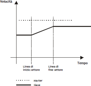
0.3.1 The sector of acceleration
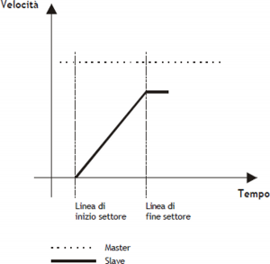
The sector of acceleration is used with slave axis stopped (slave zero speed, regardless of the speed of the master); at the end of the sector the speed of the slave is the same as that of the master.
Typical cases of acceleration are shown in A, B, C and D pictures.
In the example of A picture, at the end of the sector to be equal to that of the speed of the slave master; the law that binds the space master and slave is:
Slave space = 1/2 Master space
More smaller will be the space master considered more greater will be the acceleration gradient of the slave, which we can derive from the formula:
Time acc. slave = Master space in the sector of acc. / Maximum master speed
| In case you are facing this kind of acceleration we recommend using codeG = 132 code. |
|---|
| Picture A |
 |
Programming example:
-
codeG 132
-
codeQm Master space
-
codeQs Slave space
-
codeQma Not use
-
codeQsa Nont used
-
codeM generic code
In case you want to use the epicycloidal ramps to accelerate with the same functions described for 132 sector, simply program the sector as described above and planning codeG = 232.
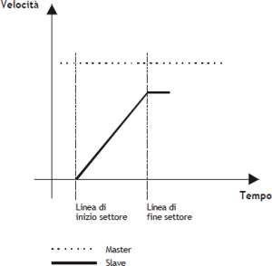
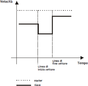
In the example of B picture, at the end of the field the speed of the slave is in proportion to the speed of the master (the proportion will be called K), the law that binds the master and slave space space is:
Slave space = K/2 Master space
More smaller will be the space master who considers, more greater will be the acceleration gradient of the slave, that we can derive from the formula:
Time of slave acc. = Master space in the acc. sector / Maximum speed master
| In case you are faced with this type of acceleration is required using codeG = 131 code. |
|---|
| Picture B |
 |
Programming example:
-
codeG 131
-
codeQm Master space
-
codeQs Slave space
-
codeQma Not used
-
codeQsa Not used
-
codeM generic code
| If you wish to use the epicycloidal ramps, we recommend using codeG = 231 code. |
|---|
In case you want to use the epicloidal ramps to accelerate with the same functions described for 131, simply program the field as described above and planning codeG = 231.
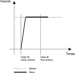
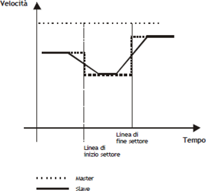
In the picture C example, more acceleration are needed, and you cannot set Master/Slave quotes of finished value. 150 sector is basically the sum of two sectors: 131 and 133. This sector is used when you know the spaces next to the field of acceleration and you want one slave very small accelerative space, even less than the unit of measurement.
The sector 150 uses the following parameters:
-
codeG : sector code (150)
-
codeQma : master space within which the slave must be at a certain speed, which we call the synchronization.
-
codeQm and codeQs : where the division indicates the relationship between the slave and master (synchronization report). These spaces will be made after accelerative section.
-
codeQsa : indicates the space into encoder pulses that must take the slave in the acceleration phase to reach the sync speed.
More smaller will be the space master who considers himself, more greater will be the acceleration gradient of the slave, who do we get from the formula:
Time of Slave acc. = Master space on the acc. sector / Maximum master speed
| In case you are faced with this type of acceleration is required using code codeG = 150. |
|---|
| Picture C |
 |
Programming example:
-
codeG 150
-
codeQm Master Space
-
codeQs Slave Space
-
codeQma Master Space in acceleration
-
codeQsa Slave SPace in acceleration (bit * 4)
-
codeM generic code
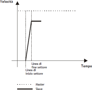
In the picture D example, more acceleration are needed, and you cannot set Master/Slave quotes of finished value. 152 sector is basically the same the sector 131. This sector is used when you know the synchronization report and you want one slave very small, even smaller than the space inertial measurement unit.
152 sector takes advantage of the following parameters:
-
codeG : sector code (152)
-
codeQma : master space within which the slave must be at a certain speed, which we call the synchronization.
-
codeQm and codeQs : where the division indicates the relationship between the slave and master (synchronization report).
-
codeQsa : indicates the space into encoder pulses that must take the slave in the acceleration phase to reach the sync speed.
More smaller will be the space master who considers himself, more greater will be the acceleration gradient of the slave, who do we get from the formula:
Time of Slave acc. = Master space on the acc. sector / Maximum master speed
| In case you are faced with this type of acceleration is required using code codeG = 152. |
|---|
| Picture D |
 |
Programming example:
-
codeG 152
-
codeQm Master Coefficient
-
codeQs Slave Coefficient
-
codeQma Master Space in acceleration
-
codeQsa Slave Space in acceleration (bit * 4)
-
codeM generic code
| If you wish to use the epicycloidal ramps, we recommend the use of the code codeG = 252. |
|---|
In case you want to use the epicycloidal ramps to accelerate with the same functions described for 152 sector, simply program the sector as described above and planning the code codeG = 252.
0.3.2 The deceleration sector
In case you need to stop the slave axis (regardless of its speed), remaining engaged with the cam (zero speed regardless of the speed of the master), it can be used the deceleration sector.
In the picture E example, at the end of the sector, the speed of the slave will be zero; la law that binds the space master and slave (the proportion between the master and the slave speed will be called K) is:
Slave space = K/2 Master space
More smaller is the space master who considers himself, more greater will be the degree of deceleration of the slave, which you can obtain from:
Time of Slave dec. = Master space in the dec. sector / Maximum master speed
| In case you find a this deceleration is obligatory the use the code codeG = 135. |
|---|
| Picture E |
 |
Programming example
-
codeG 135
-
codeQm Master space
-
codeQs Slave space
-
codeQma Not used
-
codeQsa Not used
-
codeM generic code
| If you wish to use the epicycloidal ramps, we recommend the use the code codeG = 235. |
|---|
In case you want to use the epicycloidal ramps to accelerate with the same functions described for the sector 135, simply program the field as described above and planning codeG = 235.
In the picture F example, syou need strong deceleration, and you cannot set Master/Slave dimensions of finished value. The 151 sector is basically the sum of two sectors: 133 and 135. This sector is used when you know the spaces before the deceleration area and want a space decelerativo slave very small, even smaller than the unit of measurement.
151 sector makes use of the following parameters:
-
codeG : sector code (151)
-
codeQma : master space within which the slave must be from a certain speed, which we call the zero speed synchronization.
-
codeQm and codeQs : where the division indicates the relationship between the slave and master (synchronization report). These spaces are made before decelerative section.
-
codeQsa : indicates the space into encoder pulses that must cover the slave during deceleration.
More smaller is the space master who considers himself, more greater will be the degree of deceleration of the slave, which we can derive from the formula:
Time of Slave dec. = Master space in dec. sector / Maximum master speed
:^info:^In case you find a this deceleration is obligatory the use the code codeG = 151.
| Picture F |
 |
Programming example
-
codeG 151
-
codeQm Master space
-
codeQs Slave space
-
codeQma Master space decelerating
-
codeQsa Slave space in decelerating (bit * 4)
-
codeM generic code
0.3.3 Speed change sector
| In order to do this operation there are two types of codes (codeG = 133 and codeG = 134) which differ only in the choice of the speed that you want to give to the slave at the end of the speed change sector. |
|---|
Speed change sector can be used:
-
Whenever the slave axis must reach speeds (nonzero), starting at a different speed (also non-zero).
-
Whenever the slave axis must maintain a constant speed.
In the example the speed of the slave is the same as that of the master (at the beginning of speed change sector). In case the speed is different you need to consider, in the follow formulas, the master and slave relationship of constant speed at the beginning of the sector.
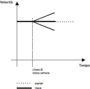
The codeG = 133 provides that the speed of the slave at the end of the sector can be different from the initial and final speed of the slave (of end time sector), will depend exclusively on the master/slave relationship of spaces (see picture G).
We have three cases:
1)Master/slave relationship < 1 Speed of the slave at the end of the sector > of the master speed
2)Master/slave relationship = 1 Speed of the slave at the end of the sector = of the master speed
3)Master/slave relationship > 1 Speed of the slave at the end of the sector < of the master speed
The speed at the end of the sector is given by the formula:
Slave Speed = Master Speed + { [ 2 (Slave Space - Master Space) / Master Space ] x 100 } %
| Picture G |
 |
Programming example:
-
codeG 133
-
codeQm Master Space
-
codeQs Slave Space
-
codeQma Not used
-
codeQsa Not used
-
codeM generic code
| If you wish to use the epicycloidal ramps, we recommend the use the code codeG = 233. |
|---|
In case you want to use the epicycloidal ramps to accelerate with the same functions described for the sector 133, simply program the sector as described above and planning codeG = 233.
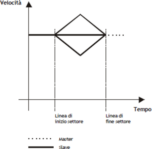
The codeG = 134 provides that the speed of the slave at the end of the sector is the same as the speed at half the slave sector will depend exclusively on the relationship of the master/slave spaces (see picture H). We have three cases:
1) Master/slave relationship < 1 Speed of the slave in the middle of the sector > of the master speed
2) Master/slave relationship = 1 Speed of the slave in the middle of the sector = of the master speed
3) Master/slave relationship > 1 Speed of the slave in the middle of the sector < of the master speed
The speed in the middle of the sector will be given by the formula:
Slave Speed = Master Speed + { [ 2 (Slave Space - Master Space) / Master Space ] x 100 } % x (Master Speed)
| Picture H |
 |
Programming example:
-
codeG 134
-
codeQm Master Space
-
codeQs Slave Space
-
codeQma Not used
-
codeQsa Not used
-
codeM generic code
| If you wish to use the epicycloidal ramps, we recommend the use the code codeG = 234. |
|---|
In case you want to use the epicycloidal ramps to accelerate with the same functions described for the sector 134, simply program the sector as described above and planning codeG = 234.
If you are programming a sector 133, 134, 233 or 234 with master and slave space to 0, it is considered as a non-operating sector (codeG = 130).
In the picture I example, wants to change speed to the slave, and it is not possible to set a Master/Slave relationship of finite value. The sector 153 is the same as sector 133. This sector is used when you know the synchronization report and you want one slave very small inertial space, sometimes even lower than the unit.
The sector 153 uses the following parameters:
-
codeG : sector code (153)
-
codeQma : master space within which the slave must be at a certain speed, which we call the synchronization.
-
codeQm and codeQs : whose division indicates the ratio between the slave and master (rapporto di sincronizzazione).
-
codeQsa : the device indicates the space in which the slave route encoder pulses to reach the sync speed after acceleration phase.
| In case you are using this type of transmission speed, we recommend the use of the code codeG = 153. |
|---|
| Picture I |
 |
Programming example:
-
codeG 153
-
codeQm Master Coefficient
-
codeQs Slave Coefficient
-
codeQma Space Master in acceleration
-
codeQsa Space Slave in acceleration (bit * 4)
-
codeM generic code
In case you want to use the epicycloidal ramps to accelerate with the same functions described for the sector 154, simply program the sector as described above and planning codeG = 253.
In the example of L picture, you want to bring the slave at a speed without having to run a connection ramp. The sector 154 unlike all other, forces the initial velocity equal to the final speed while maintaining a constant speed between two points. This sector can be used as the starting sector of the cam (starting without acceleration), as intermediate sector or final sector (stop without ramp).
The sector 154 uses the following parameters:
-
codeG : sector code (154)
-
codeQma : Softening sector type
-
codeQm and codeQs : whose division indicates the relationship between the slave and master (synchronization relationship). These spaces are performed during the sector.
-
codeQsa : if set to 0 indicates that the next sector is an area of movement, if set to 1 indicates that the next sector does not provide for movement (deceleration with zero ramp).
| In case you have to use this type of movement is obligatory the use of the code codeG = 154. |
|---|
| Picture L |
 |
Programming example:
-
codeG 154
-
codeQm Master Space
-
codeQs Slave Space
-
codeQma Softening sector type
-
codeQsa
0 = next sector of movement
1 = stationary axis in the next sector
2 = Gearing axis -
codeM generic code
0.3.4 Softening sector type
From the graph in Picture L speed steps can be seen in the change between one sector and the subsequent. To eliminate the steps has been included exchange softening sector function which plan to put a ramp smoothing between the two sectors so as to make it less “rough” switching between one sector and the subsequent.
Programming the softening can be done by simply entering in codeQma, taking advantage of the half, a third, a fourth or a fifth of the smallest sector. Softening only runs between two adjacent 154 sectors, without having put no codeG different (counter change, jump, etc.).
| Picture M |
 |
The codeQma has the following meaning:
-
0 = No softening
-
1 = Soften 1/2 smaller sector
-
2 = Soften 1/3 smaller sector
-
3 = Soften 1/4 smaller sector
-
4 = Soften 1/5 smaller sector
In case you want to use the ramps to epicycloidal speed variations, respect the same functions described for 154 sector, simply program the sector as described above and use the code G=254.
0.3.4.1 Sector set as "Gearing"
To schedule a sector as gearing you must program the parameters as described below:
codeG1 = 154
codeQma1 = 0
codeQsa1 = 2
codeQm1 = numerator of the speed ratio
codeQs1 = denominator of thespeed ratio
Once given the command of the Startcam, the only editable values are codeQs and codeQsa, If other values are changed with the cam running could result in the error 5 and the device goes into emergency.
The relationship between codeQm and codeQs points, respectively, the Master/Slave relationship electric Gearing, and in particular this report can be changed dynamically (with cam running) acting only on the parameter codeQs. These parameters follow always the law of minimum space at sampling time (that is, the space made by the master in a sampling time of the device, must be less than the maximum speed set to codeQm), so, in order to avoid errors on the cam, it is better to set sufficiently high values; example, the ratio is 1:1 the values might be codeQm = 1000 and codeQs = 1000.
The new speed of the Slave due to the new ratio is reached immediately from the axis without any ramp, so if you want to have a smooth change of speed you should gradually change the relationship until you reach the desired.
If you set the value 0 or 1 on codeQsa you go on to the next sector (If you have not planned any sector later to stop the device simply give a Stop-cam).
During this last feature parameters posit and positm lose their meaning as they are continuously reported at a value corresponding to half of the spaces planned in codeQm and codeQs.
0.3.5 The Start sector synchronized to the Master
Many times there is a need to start the slave on the master known, but there is the possibility to connect to a proximity sensor. The only constraint is that the sector containing the codeG 160 must be the first sector of cam motion and cannot be placed in the loop. At the STARTCAM command, the st_camex state goes to 1 and the the movement of the Slave axis begins only at Master quota (expressed in units of measurement) set in the sector 160 and from there will follow the trend described in the following sectors.
If the STARTCAM command is given with the above-quota master count, is set the warning 9; under these conditions the Master counting must become less than the quota set for it to be in the right situation of the system.
You can't get into a sector with codeG = 160 coming from a jump or a loop cam (error 7).
Programming example:
-
codeG 160
-
codeQm STARTCAMMA quota expressed in units of measurement
-
codeQs Not used
-
codeQma Not used
-
codeQsa Not used
-
codeM Not used
0.3.6 The end cam sector
The exchange end cam sector (codeG = 136), is used whenever one has to conclude the cam (disengage the cam) stopping the slave axis in reaction to space on the last point of the cam. The slave axis must be stopped at the time of the release of the cam, pwhereby it is assumed that the previous sector contains the code of the deceleration (codeG = 135).
After this area the cam is released and, to reattach it, you have to send the STARTCAM command.
Programming example:
-
codeG 136
-
codeQm Not used
-
codeQs Not used
-
codeQma Not used
-
codeQsa Not used
-
codeM Not used
0.3.7 Absolute jump sector
The absolute jump sector (codeG = 137), is used to jump to a sector (defined in the codeQm) in order to change the fly cam performance according to the conditions established by the programmer.
The most common situation for using this feature is that a portion of the cam that needs to be repeated several times.
Keep in mind that the counts are not updated, and then in the long run can go into overflow. Therefore, use the update count fields in the field that precedes the one containing the codeG = 137.
Programming example:
-
codeG 137
-
codeQm Sector number to jump
-
codeQs Not used
-
codeQma Not used
-
codeQsa Not used
-
codeM Not used
0.3.8 Conditional jump sector
The conditional jump sector (codeG = 190), is used to make a jump to a sector (defined in the codeQm) for a number of times (defined in the codeQs) after that you move on to the next sector. The count of the number of the jumps performed is available in codeQma.
Care must be taken that the counts are not updated, and then in the long run can go into overflow. Therefore, use the update count sector in the field that precedes the one containing the codeG = 190.
Programming example:
-
codeG 190
-
codeQm Sector number to jump
-
codeQs Number of times
-
codeQma Jump number viewing
-
codeQsa Not used
-
codeM Not used
0.3.9 Loop cam sector
The loop sector cam (codeG = 138), is used to repeat the cam running from the sector number one, eliminating by removing both master and slave counts.
We recommend using this code in repeated endlessly cams that have no problems with subtraction of counts.
Programming example:
-
codeG 138
-
codeQm Not used
-
codeQs Not used
-
codeQma Not used
-
codeQsa Not used
-
codeM Not used
0.3.10 Not operative sector
The not operative sector (codeG = 130), is used to reserve areas to perform functions only under special conditions defined by the programmer.
For example you may consider a cam for the flying saw, in which you have to reserve the sectors to be used in case, mechanically, you cannot make the cut master space reserved for this operation.
Programming example:
-
codeG 130
-
codeQm Not used
-
codeQs Not used
-
codeQma Not used
-
codeQsa Not used
-
codeM Not used
0.3.11 Definition of area sampled zero sectors
All sectors that require no space master to be processed are called “zero-sampling”; specifically, are all NOP, JUMP, LOOP and END sectors.
A sector zero sampling is also considered the codeG = 133 se programmato come:
-
codeG = 133
-
codeQm = 0
-
codeQs = 0
It is not possible to sequence more than 9 zero sampling areas.
0.3.12 Update count sectors
The update count is used to make an exchange of the count, to values that may indicate the actual physical location of the axis. The most typical case is the circular axis (from 0° to 360°): whenever you reach 360° you must subtract a circle. To make an update count there are multiple codes of subtraction or bit encoder count setting, whether that unit of measure. For how it is structured the device, it is not possible to sequence more than 4 sectors count update. The following table containing the description of what happens during the update count based on the code used.
| codeG | Execute operations |
|---|---|
| 139 | Subtraction by count master value contained in the codeQm (expressed in units of measurement). Subtraction from the slave count value contained in codeQs (expressed in units of measurement). |
| 140 | Forcing master count to the value that is contained in codeQm (expressed in units of measurement). |
| 141 | Forcing the slave to the count value in codeQs (expressed in units of measurement). |
| 142 | Forcing master count to the value that is contained in codeQm (expressed in units of measurement). Forcing the slave to the count value in codeQs (expressed in units of measurement). |
| 143 | Subtracting the value contained in the master count codeQm (expressed in bit encoder multiplied by 4). Subtracting the slave count value contained in codeQs (expressed in bit encoder multiplied by 4). |
| 144 | Forcing master count to the value that is contained in codeQm (expressed in bit encoder multiplied by 4). |
| 145 | Forcing the slave to the count value in codeQs (expressed in bit encoder multiplied by 4). |
| 146 | Forcing master count to the value that is contained in codeQm (expressed in bit encoder multiplied by 4). Forcing the slave to the count value in codeQs (expressed in bit encoder multiplied by 4). |
0.3.13 Cam sectors description
| CodeG | codeQm | codeQs | codeQma | codeQsa | codeM | Description |
|---|---|---|---|---|---|---|
| 130 | n.u. | n.u. | n.u. | n.u. | n.u. | NOP: Disabled sector (not operative) |
| 131 | Increase Master (Um) | Increase Slave (Um) | n.u. | n.u. | c.u. | AZL: Sector of acceleration with zero initial speed and final speed calculated according to slave space to go. Final slave speed = f (slave space). |
| 132 | Increase Master (Um) | Increase Slave (Um) | n.u. | n.u. | c.u. | AZM: Sector of acceleration with zero initial speed and final velocity equal to that of the master (final slave speed = master speed), by varying the degree of acceleration. |
| 133 | Increase Master (Um) | Increase Slave (Um) | n.u. | n.u. | c.u. | RSC: Intermediate sector (fitting without compensation) with speed velocity equal to the final speed of the previous sector and final speed calculated according to slave space to go. |
| 134 | Increase Master (Um) | Increase Slave (Um) | n.u. | n.u. | c.u. | RCC: Intermediate sector (fitting with compensation) with initial and final speed equal to the final speed of the previous sector. This is obtained by a slave space clearing, dividing into two phases (acceleration and deceleration) the execution of the sector. |
| 135 | Increase Master (Um) | Increase Slave (Um) | n.u. | n.u. | c.u. | DZC: Sector of deceleration with initial speed equal to the final speed of the previous sector and final speed equal to zero. This is obtained by a slave space clearing, dividing into two phases the execution of the sector. |
| 136 | n.u. | n.u. | n.u. | n.u. | n.u. | END: End cam. The system releases the running cam and remains in the reaction of space with the slave on the last position elaborated by the previous sector. |
| 137 | Sector number to which jump | n.u. | n.u. | n.u. | n.u. | ABJ: Absolute jump. The system maintains the position and speed of the last sector used. The counters do not vary. The number of the cam that I miss all indicated in codeQm and must be between 1 and 128. |
| 138 | n.u. | n.u. | n.u. | n.u. | n.u. | LOOP: Loop cam. When this instruction is encountered resumes processing industries from the first, keeping them as speed than the last sector tried and subtracting the count of the amount of space done up to that point. |
| 139 | Subtraction Master count value (Um) | Subtraction Slave count value (Um) | n.u. | n.u. | n.u. | SMS: Subtract the counts in units. Is subtracted from the count of the Master the value contained in the codeQm and the Slave count the value contained in the codeQs (subtraction Master and Slave counting in units of measurement). |
| 140 | New Master counter (Um) | n.u. | n.u. | n.u. | n.u. | NCM: Change master counter. Writes the value contained in the codeQm in the Master counter. The updating is done by subtraction (updates the Master count unit of measure). |
| 141 | n.u. | New Slave counter (Um) | n.u. | n.u. | n.u. | NCS: Change Slave count. Writes the value in codeQs in the counting of the Slave. The updating is done by subtraction (updates the slave counter in unit of measure). |
| 142 | New Master counter (Um) | New Slave counter (Um) | n.u. | n.u. | n.u. | NMS: Change counters. Master and Slave counts are written out with the values found respectively at codeQm and codeQs (updates the master and slave counters in unit of measure). |
| 143 | The subtraction Master counter value (bit*4) | The subtraction Slave counter value (bit*4) | n.u. | n.u. | n.u. | SBMS: Subtract the Master and Slave bit counts. Subtracts the value in Master codeQm counter and the counter of the Slave the value in codeQs (master and slave bit count x 4 subtraction ). |
| 144 | New Master counter (bit*4) | n.u. | n.u. | n.u. | n.u. | NBM: Change Master counter in bit. The value is written in codeQm of the Master counting. The updating is done by subtraction (updates the master counter in bit x 4). |
| 145 | n.u. | New slave counter (bit*4) | n.u. | n.u. | n.u. | NBS: Change Slave counter in bit. The value is written in codeQs of the Master counting. The updating is done by subtraction (updates the slave counter in bit x 4). |
| 146 | New Master counter (bit*4) | New Slave counter (bit*4) | n.u. | n.u. | n.u. | NBMS: Change Master and Slave counters in bit. The values are upgrade the Master and Slave counters with the values found respectively at codeQm and codeQs (update the master and slave counter in bit x 4). |
| 150 | Increase Master (Um) | Increase Slave (Um) | Master Space in acceleration (Um) | Slave SPace in acceleration (bit*4) | c.u. | AZMC: Acceleration sector with zero initial speed and final speed calculated according to Master and Slave space indicated in codeQm and codeQs. The acceleration is performed in the space indicated in codeQma and codeQsa. Run the spaces indicated in codeQm and codeQs with the law described in the codeG 133. |
| 151 | Increase Master (Um) | Increase Slave (Um) | Master Space in deceleration (Um) | Slave Space in deceleration (bit*4) | c.u. | DZMC: Deceleration sector with initial speed equal to the final speed of the previous sector and final speed equal to zero. The deceleration is performed in the space indicated in codeQma and codeQsa. Run the spaces indicated in codeQm and codeQs with the law described in the codeG 133. |
| 152 | Master Coefficent | Slave Coefficent | Master Space in acceleration (Um) | Slave space in acceleration (bit*4) | c.u. | AZMS: Acceleration sector with zero initial speed and final speed calculated according to Master and Slave coefficients indicated in codeQm and codeQs. The acceleration is performed in the space indicated in codeQma and codeQsa. Do not run the spaces indicated in codeQm and codeQs. |
| 153 | Master Coefficent | Slave Coefficent | Master Space in speed change (Um) | Slave Space in speed change (bit*4) | c.u. | NVSR: Change speed on ramps: the Slave axis moves from the current speed at the speed calculated according to Master and Slave coefficients indicated in codeQm and codeQs. The speed change uns in space indicated in codeQma and codeQsa. Do not run the spaces indicated in codeQm and codeQs. |
| 154 | Increase Master (Um) | Increase Slave (Um) | Type of softening | Sector type | c.u. | NVS: Change speed without ramp. The Slave axis moves from the current speed at the speed calculated according to master and slave spaces listed in codeQm and codeQs without ramp (run the step). In the codeQsa indicates whether this is the last sector (by setting 1 indicates that the next time the slave axis is stopped) or if the movement continues (setting 0 indicates that the next time the slave axis is of movement) setting to 2 on codiceQsa you can use the axis as GEARING. Once you have set the codeQm and codeQs so you get the MASTER/SLAVE speed ratio. The new R.V. is obtained without ramp so if you want a smooth change you have to change the codeQs. Changing the codeQa (back to 0 or 1) you move on to the next sector (If you haven't planned any sector later to stop the device simply give one Stopcam otherwise you run into an error). N.B. During this last feature parameters posit and positm lose their meaning given that remain fixed at a value corresponding to half of the spaces planned in codeQm and codeQs. See the chapter for other informations |
| 160 | Master Quota (Um) | n.u. | n.u. | n.u. | c.u. | STS: Synchronized Start to the STARTCAM expects the Master axis exceeds the height indicated in codeQm to move to the next sector. Sectors earlier than this should not be about movement and this code cannot be placed in the loop cam. |
| 190 | Sector number to which jump | Number of times | Displaying number of jumps | n.u. | c.u. | CNJ: Conditional Jump. The system maintains the position and speed of the last sector developed. The counters do not vary. The number of the cam that I miss all indicated in codeQm and must be between 1 and 128. The jump is repeated as many times as indicated in codeQs. |
| 231 | Increase Master (Um) | Increase Slave (Um) | n.u. | n.u. | c.u. | AZLE: Sector zero initial speed and Acceleration with planetary final velocity calculated according to slave space to go. Final Slave speed = f (slave space). |
| 232 | Increase Master (Um) | Increase Slave (Um) | n.u. | n.u. | c.u. | AZME: Epicycloidal acceleration sector with zero initial speed and final velocity equal to the master (Final Slave speed = master speed), by varying the degree of acceleration. |
| 233 | Increase Master (Um) | Increase Slave (Um) | n.u. | n.u. | c.u. | RSCE: Epicycloidal intermediate sector (fitting without compensation) with initial velocity equal to the final speed of the previous sector and e final velocity calculated according to slave space to go. |
| 234 | Increase Master (Um) | Increase Slave (Um) | n.u. | n.u. | c.u. | RCCE: Epicycloidal intermediate sector (fitting with compensation) with initial and final speed equal to the final speed of the previous sector. Is obtained by the Slave Space compensation, dividing in two stages (acceleration and deceleration) the sector execution. |
| 235 | Increase Master (Um) | Increase Slave (Um) | n.u. | n.u. | c.u. | DZCE: Epicycloidal deceleration sector with initial speed equal to the final speed of the previous sector and final speed equal to zero. Is obtained by a slave space compensation, dividing into two stages the sector execution. |
| 252 | Master Coefficent | Slave Coefficent | Master Space in acceleration (Um) | Slave Space in acceleration (bit*4) | c.u. | AZMSE: Epicycloidal acceleration sector with initial speed to zero and final speed calculated on the basis of Master and Slave coefficients indicated in codeQm and codeQs. The acceleration is performed in the space indicated in codeQma and codeQsa. Do not run the spaces indicated in codeQm and codeQs. |
| 253 | Master Coefficent | Slave Coefficent | Master Space in change speed (Um) | Slave space in change speed (bit*4) | c.u. | NVSRE: Epicycloidal gear speed ramping. The Slave axis moves from the current speed at the speed calculated according to Master and Slave coefficients indicated in codeQm and codeQs. The speed change is executed in the space indicated in codeQma and codeQsa. Do not execute the spaces indicated in codeQm and codeQs |
| 254 | Increase Master (Um) | Increase Slave (Um) | Type of softening | Sector type | c.u. | NVSE: Change speed without ramp. The Slave axis moves from the current speed at the speed calculated according to Master and Slave coefficients indicated in codeQm and codeQs without ramp (execute the step). In the codeQsa indicates that this is the last sector (by setting 1 indicates that the next sector the slave axis is stopped) or if the movement continues (setting 0 means that the slave axis is in movement in next sector). (See the chapter for other informations). |
Legend:
n.u.: Not used
c.u.: User code
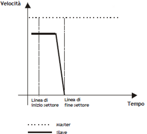
0.3.14 Basics for building a cam to wire-guides
As an example, consider a simple wire-guides:
-
Starting with acceleration ramp.
-
Achieving a speed proportional to that of the master.
-
Maintenance of speed for the entire journey.
-
Stop with deceleration ramp.
-
Stop the axis for some space of the master.
-
Return to the starting point with the same stroke mode.
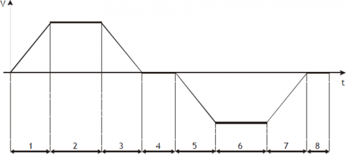
Sector 1 Acceleration, from zero speed and positive shift slave (codeG = 131). It is important to calculate the ratio of space master/slave of this section so that the output speed is the one that will be maintained by the slave axis in the stretch at constant speed.
Sector 2 Intermediate with constant speed and positive shift slave (codeG = 133).
Sector 3 Deceleration with final zero speed, with a possible braking speed compensation in the first half of the stroke and the slave positive displacement (codeG = 135). May have the same values set in the field 1.
Sector 4 Stop working with slave zero shift (codeG = 133). Programming master space while the slave is set to 0.
Sector 5 Acceleration, from zero speed and negative shift slave (codeG = 131). It is important to calculate the ratio of space master/slave of this section so that the output speed is the one that will be maintained by the slave axis in the stretch at constant speed. Ideally, you can use the same values entered in the sector 1 changing the quota sign slave.
Sector 6 Intermediate with constant speed and negative shift slave (codeG = 133).
Sector 7 Deceleration with final zero speed, with a possible braking speed compensation in the first half of the stroke and negative shift slave (codeG = 135). May have the same values set in the sector 5.
Sector 8 Stop working with slave zero shift (codeG = 133). Programming master space while the slave is set to 0.
After you run the sector 8, there must be some functions that perform power factor correction of Master and Slave counters by subtracting the space covered until the end of the sector; then you will have to have the automatic replay same cam from sector 1 (JUMP or loop cam).
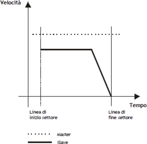
0.3.15 Basics for building a cam for fly cut with extra speed
As an example, consider a simple fly cut:
-
Start slave axis with acceleration ramp.
-
Achievement of the master speeed.
-
Maintaining the speed reached throughout the cut.
-
Finished cutting, the slave axis must accelerate to go to go to an extra speed, keeping it for a certain space.
-
Stop slave axis with deceleration ramp.
-
Return of the slave axis to the starting point (home), without inversion time and following the acceleration and deceleration ramps.
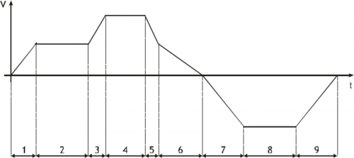
Sector 1 Acceleration, with starting from zero speed and positive shift slave (codeG = 132). At the end of this sector the slave will have the same speed of the master.
Sector 2 Intermediate with constant speed and positive shift slave (codeG = 133). In this area the space covered by the master is the same as the path from the slave.
Sector 3 Positive acceleration and displacement slave (codeG = 133). The code set rule slave acceleration than the master, it sets a space more than the master.
Sector 4 Intermediate with constant speed and positive shift slave (codeG = 133). In this area the space covered by the slave will be proportion to that route from the master.
Sector 5 Deceleration and positive shift slave (codeG = 133). In this sector takes the slave at the same speed as the master.
Sector 6 Deceleration with final zero speed, with a possible braking speed compensation in the first half of the stroke and the slave positive displacement (codeG = 135).
Sector 7 Acceleration, with starting from zero speed and negative shift slave (codeG = 131). In this area the output speed of the slave may differ from that of the master.
Sector 8 Intermediate with constant speed and negative shift slave (codeG = 133).
Sector 9 Deceleration with final zero speed, with a possible braking speed compensation in the first half of the stroke and negative shift slave (codeG = 135).
After you run the sector 9, there must be a function that performs the power factor of the counter of the Master, subtracting the space covered until the end of the field and, subsequently, automatically resubmitting the same cam (JUMP or loop cam).
0.4 Device errors management
A bug in the system camming is reported by the st_error state.
Being caused by a serious event and not being guaranteed in this situation the slave axis management, It was decided arbitrarily to block the axis without ramps as had taken place an emergency.
When st_error is equal to 1, are present on the errcode variable the type of error occurred (see the table) and in errvalue variable an indication on the cause of the error.
| Code | Priority | Description |
|---|---|---|
| 1 | 0 | Too many consecutive invalid sampling areas |
| 2 | 0 | JUMP from one sector with final nonzero speed on a sector with zero initial speed (acceleration). |
| 3 | 0 | G code of the invalid sector. |
| 4 | 0 | Master space of the cam sector too small, so the sector is not calculated. |
| 5 | 0 | Attempted to write in the sector running. |
| 6 | 0 | Into the JUMP code, was required to go to a row between 1 and 128. |
| 7 | 0 | Sector with codeG = 160 don't run at the beginning of the cam. |
If the device goes in error, in order to start cut you have to clear the st_error status through RSERR command and then the usual routine of emergency recovery (RESUME axis).
NOTE: Error 4 is due to the fact that the sector is run in a time less than the sampling time of the device, so it cannot be tried. If you are in this situation you have to increase the share of the master in the sector, or lower the speed of the master.
0.5 Device warning management
The presence of a warning system camming is signaled by the st_warning state.
Being caused by a minor event and being guaranteed in this situation the slave axis management, the slave axis continues his work.
When st_warning is equal to 1, are present on the wrncode variable the type of warning intervened (see the table) and in the wrnvalue variable the sector number of the cam that caused the warning.
| Code | Priority | Description |
|---|---|---|
| 1 | 6 | Constant acceleration sector greater than that programmed. |
| 2 | 7 | Constant deceleration sector greater than that programmed. |
| 3 | 4 | Slave to + 10V analog saturation (with latching) |
| 4 | 5 | Saturation of the slave - 10V analog (with latching) |
| 5 | 9 | Final speed of opposite sign to the initial speed. |
| 6 | 2 | Met a new sector of acceleration when the cam comes from an area with non-zero final speed. |
| 7 | 8 | Medium speed of opposite sign to the initial speed. |
| 8 | 0 | Event captured from the interrupt input but not processed immediately due to overload in the calculations of the device. |
| 9 | 1 | Starting quota Slave axis with codeG = 160 already outdated |
| 10 | 10 | Were encountered two sectors with codeG 154 It has not been executed softening ramp even if enabled |
| 11 | 11 | CQCL command not executed for not met conditions |
| 12 | 3 | Axis out of sync threshold (syncrange variable) |
The highest priority is marked from 0, the lowest with 8.
To clear the st_warning status must send the RSWRN command.
NOTE: In case of warning 8, the function will be delayed long enough to allow the CPU to terminate the internal calculations. In the case of cam start from the interrupt input, the startup location cam can not be that of the moment of interrupt, but that after the end of the calculations. The execution time of calculations (expressed as sampling time of the device), is shown in the following table:
| Parameters involving recalculations | N.r samples that are distributed the consequential recalculations |
|---|---|
| codeG, codeQs, codeQm,codeQsa, codeQma, maxpos, minpos,prspos, prsposm,toll, tacc, tdec, taccmax, tdecmax, syncrange, pgain, feedfw, integt, derivt | 1 |
| tbfm | 2 |
| tbf | 3 |
| maxvel | 5 |
| decpt, unitvel | 6 |
| pulsem, measurem | 130 |
| pulse, measure | 139 |
0.6 Simulated master management
| The encoder device master of CAMMING3 is in no way linked to the encoder EANPOS device. |
|---|
The device CAMMING3 can handle two types of master:
-
Both may be coming from an encoder mechanically connected to the master system and electrically connected to the system QMOVE or simulated encoder. It also accepted the mixed solution (one connected electrically and one simulated). The exchange between the two encoder is done through the parameter mtype without any constraint, so that even in the execution of a cam, you can make the exchange between devices. On your system using the device CAMMING3 can be declared a simulated encoder using a device of movement (for example the EANPOS) declared with the counter on slot 1 (normally reserved to the CPU of the system) and any other disable devices:
;-----------------------------
; Internal Device declaration
;-----------------------------

INTDEVICE
<device_name>   EANPOS   TCamp   ICont   IntL   IAZero   IOutA
Master          EANPOS   2       1.CNT01 X      X.X      X.X
where:
| <device name> | The name assigned to the device. |
| EANPOS | Keyword that identifies the device analog positioner. |
| TCamp | Sample time device (1÷255 ms). |
| ICont | Bidirectional counter input. |
| IntL | Number of the interrupt line dedicated to the encoder zero pulse during the research phase of presets. |
| IAZero | Enable input to acquire the transducer's zero pulse during the quest activity phase of presets. |
| IOutA | Hardware address of the DAC from analog output (must be stated as X. X). |
The device thus configured as a simulated master and is parameterized and used like a normal device bearing in mind that the control loops must be open (st_loopon = 0) and therefore don't need to parameterize the P.I.D. but just set the feedforward to 100% (feedfw = 1000).
0.6.1 Programming example
We use the EANPOS device configured as in the previous example, and you want to give the set of speed (setvel) expressed in Hz. It is assumed that the master simulated should continue its movement ad infinitum.
The sf01 flag for the start and stop simulated device.
;----------------------------------------------------
; Simulated master management
;----------------------------------------------------

Master:measure = 1000
Master:pulse = 4000
Master:decpt = 0
Master:unitvel = 1
Master:maxvel = 1000
Master:taccdec = 100
Master:maxpos = 999999
Master:minpos = -999999
INIT Master
WAIT Master:st_init
LOOPOFF Master
WAIT NOT Master:st_loopon
RESUME Master
WAIT NOT Master:st_emrg

MAIN:
IF sf01
  IF Master: st_still
    Master:posit = 0
    Master:setvel = 500
    Master:setpos = 999999
    START Master
  ENDIF
  IF Master:posit GE 500000
    Master:posit = 0
  ENDIF
ELSE
  IF NOT Master:st_still
    STOP Master
  ENDIF
ENDIF

WAIT 1
JUMP MAIN
END
0.7 M/S Transducer frequency ratio limitation
To have a proper functioning during synchronisation, It is required that the pulses in the time (frequency) generated from ther Master transducer are greater or equal to those of the Slave axis. In any case you are required to comply with the condition
Slave frequency = 1,5 × Master frequency
In the case of a failure to comply with this condition will cause trouble in the calibration of the Slave axis in synch because of a roughness in the movement.
0.8 Inputs configuration table
The device has the ability to manage a normal entrance and an interrupt input to run commands or perform actions. The address of the inputs can be setting in the configuration file (InG and InGInt). To perform a specific function at the entrance, simply assign at the funInp variable (If this is the normal input) or funInt variable (If this is the interrupt input) the code listed in the following table.
| Code | Input function |
|---|---|
| 00 | Input disabled |
| 01 | STOPCAM |
| 02 | STARTCAM |
| 03 | Writes the value of the encoder in the delta1 variable |
| 04 | Writes the value of the encoderm in the delta2 variable |
| 05 | Increments of 1 the delta1 variable |
| 06 | Increments of 1 the delta2 variable |
| 07 | Writes the contents of the delta1 variable in encoder |
| 08 | Writes the contents of the delta2 variable in encoderm |
| 09 | Writes the value of the encoder in the delta1 variable + STARTCAM |
| 10 | Writes the value of the variable encoderm in the variable delta2 + STARTCAM |
| 11 | Writes the value of the variable encoder in the variable delta1 + STARTCAM; STOPCAM command is blocked for a time of 25 mSec. |
| 12 | Writes the value of the variable encoderm in the variable delta2 + STARTCAM; STOPCAM command is blocked for a time of 25 mSec. |
All functions of the inputs can be handled either on normal inputs on interrupt inputs.
To have a correct operation of the inputs, they are enabled by respecting the conditions set out in the description of the command or action described.
0.9 Outputs configuration table
The device has the ability to handle an exit to signal certain states. The address of the output can be setting in the configuration file (Out). To perform a specific function on output, simply assign the variable funOut code shown in the following table.
| Code | Output function |
|---|---|
| 00 | Output disable |
| 01 | Disabling output |
| 02 | Enable output |
| 03 | st_toll |
| 04 | st_tpos |
| 05 | st_sync |
| 06 | It activates output only if codeMex is equal to the value 1000 |
| 07 | It activates output only if codeMex is equal to the value 1000 and st_sync is active |
| 08 | It activates output only if codeMex is equal to the value 1001 |
| 09 | It activates output only if codeMex is equal to 1002 |
0.10 Table commands, states and parameters: Symbols used
The parameter name, condition or command is taken back to the left of the table
R
Indicates whether its parameter or state is retentive (upon initialization of the device maintains the previously defined), or the state assumes upon initialization of the device.
R = Retentive
0 = Upon initialization of the device the value is forced to zero.
1 = Upon initialization of the device the value is forced to one.
D
Indicates the size of the parameter.
F = Flag
B = Byte
W = Word
L = Long
0.10.0.1 Condizioni
Vengono descritte tutte le condizioni necessarie affinché il parametro sia considerato corretto o perché il comando venga accettato.
In alcuni casi vengono specificati dei valori limite per laccettazione del parametro: se vengono introdotti dei valori esterni ai limiti impostati, il dato viene comunque accettato; pertanto devono essere previsti opportuni controlli interni tali da garantire il corretto funzionamento.
Per lesecuzione di un comando, tutte le relative condizioni devono necessariamente essere soddisfatte; in caso contrario il comando non viene eseguito.
A
Indica la modalità di accesso.
Rd = Read (lettura).
Wr = Write (scrittura).
RdWr = Read and Write (lettura e scrittura).
0.10.1 PARAMETRI
| Nome | D | Condiz. scritt. | R | A | Descrizione |
|---|---|---|---|---|---|
| decpt | B | st_still = 1 st_camex = 0 st_prson = 0 | R | RdWr | Decimal point (0÷3) Definisce la precisione con la quale si intendono impostare le preselezioni e visualizzare i conteggi relativamente allasse slave. |
| measure | L | st_still = 1 st_camex = 0 st_prson = 0 | R | RdWr | Measure (1÷999999) Indica lo spazio, in unità di misura, percorso dallasse slave per ottenere gli impulsi encoder impostati nel parametro pulse. Questo parametro è utilizzato per il calcolo della risoluzione dellasse con la formula: Risoluzione = measure* 4 / pulse La risoluzione deve avere un valore compreso tra 0.00374 e 4.00000. |
| pulse | L | st_still = 1 st_camex = 0 st_prson = 0 | R | RdWr | Pulse encoder (1÷999999) Indica gli impulsi moltiplicato 4 forniti dallencoder slave per ottenere lo spazio impostato nel parametro measure. Questo parametro è utilizzato per il calcolo della risoluzione dellasse con la formula: Risoluzione = measure* 4 / pulse La risoluzione deve avere un valore compreso tra 0.00374 e 4.00000. |
| measurem | L | st_still = 1 st_camex = 0 st_prson = 0 | R | RdWr | Measure of master (1÷999999) Indica lo spazio, in unità di misura, percorso dallasse master per ottenere gli impulsi encoder impostati nel parametro pulsem. Questo parametro è utilizzato per il calcolo della risoluzione dellasse con la formula: Risoluzione = measurem * 4 / pulsem La risoluzione deve avere un valore compreso tra 0.00374 e 4.00000. |
| pulsem | L | st_still = 1 st_camex = 0 st_prson = 0 | R | RdWr | Pulse encoder of master (1÷999999) Indica gli impulsi moltiplicato 4 forniti dallencoder master per ottenere lo spazio impostato nel parametro measurem. Questo parametro è utilizzato per il calcolo della risoluzione dellasse con la formula: Risoluzione = measurem* 4 / pulsem La risoluzione deve avere un valore compreso tra 0.00374 e 4.00000. |
| unitvel | B | st_still = 1 st_camex = 0 st_prson = 0 | R | RdWr | Velocity unit (0÷1) Definisce se lunità di tempo della velocità dello slave è espressa in minuti o secondi. 0 = Um/min, 1 = Um/sec. |
| maxvel | L | st_still = 1 st_camex = 0 st_prson = 0 | R | RdWr | Max velocity (0÷999999) Definisce la massima velocità dellasse slave (relativa al riferimento analogico di +/-10V). Il valore introdotto è nellunità di tempo della velocità impostata nel parametro unitvel. |
| prsvel | L | st_prson = 0 | R | RdWr | Preset velocity (0÷maxvel) Definisce la velocità dellasse slave durante la procedura di ricerca di preset. Il valore introdotto è nellunità di tempo della velocità impostata nel parametro unitvel. |
| taccmax | W | st_prson = 0 | R | RdWr | Max acceleration time (0÷999) Usato durante l'esecuzione della camma per eseguire le comparazioni sul gradiente di accellerazione massimo. Definisce il tempo minimo di accelerazione con cui l'asse Slave può portarsi da zero alla velocità massima. Il valore introdoto è espresso in cnetesimi di secondo. |
| tdecmax | W | st_prson = 0 | R | RdWr | Max deceleration time (0÷999) Usato durante lesecuzione della camma per eseguire le comparazioni sul gradiente di decelerazione massimo. Definisce il tempo minimo di decelerazione con cui lasse slave può portarsi da velocità massima ad asse fermo (velocità uguale a zero). Il valore introdotto è espresso in centesimi di secondo. |
| tacc | W | - | R | RdWr | Acceleration time (0÷999) Tempo impiegato dallasse slave per portarsi da fermo alla velocità massima. Il valore introdotto è espresso in centesimi di secondo. Se lasse si sta muovendo (st_still = 0) si possono cambiare i gradienti della rampa solamente se i nuovi valori consentono di raggiungere la quota impostata. |
| tdec | W | - | R | RdWr | Deceleration time (0÷999) Tempo necessario allasse slave per decelerare dalla velocità massima a zero (condizione di asse fermo). Il valore introdotto è espresso in centesimi di secondo. Se lasse si sta muovendo (st_still = 0) si possono cambiare i gradienti della rampa solamente se i nuovi valori consentono di raggiungere la quota impostata. |
| maxpos | L | st_still = 0 | R | RdWr | Max position (-999999÷999999) Massima quota raggiungibile dallasse slave. Tale limite non è controllato durante lesecuzione della camma. |
| minpos | L | st_still = 0 | R | RdWr | Min position (-999999÷999999) Minima quota raggiungibile dallasse slave. Tale limite non è controllato durante lesecuzione della camma. |
| prspos | L | st_still = 0 | R | RdWr | Preset position (minpos÷maxpos) Valore che viene caricato sul conteggio slave con la procedura di ricerca di preset. |
| prsposm | L | st_prsonm = 0 | R | RdWr | Preset position of master (-999999 ÷999999) Valore che viene caricato sul conteggio master con la procedura di ricerca di preset. |
| toll | L | st_still = 0 | R | RdWr | Tolerance (0÷999999) Fascia di conteggio intorno alle quote di posizionamento dellasse slave. Se il posizionamento (non larrivo in camma) si conclude entro tale fascia, è da considerarsi corretto e viene segnalato attraverso lo stato st_toll. |
| maxfollerr | L | - | R | RdWr | Maximum following error (0÷2 31-1) Massimo scostamento accettabile tra la posizione teorica e la posizione reale dellasse slave. Il valore introdotto è espresso in bit trasduttore per 4. |
| syncrange | L | - | R | RdWr | Synchronism range (0÷999999) Valore espresso in unità di misura entro il quale viene segnalato il sincronismo slave (st_sync = 1) rispetto al master durante lesecuzione della camma. |
| prsmode | B | st_prson = 0 | R | RdWr | Preset mode (0÷2) Definisce il tipo di ricerca di preset dello slave: 0 = Per la ricerca dellabilitazione impulso di zero, lasse inizia il movimento in veloce, incontra il segnale di abilitazione, inverte la direzione rallentando e, sul fronte di discesa relativo al segnale di abilitazione dellasse slave, carica la quota di preset; 1 = Per la ricerca dellabilitazione impulso di zero, lasse inizia il movimento in veloce, incontra il segnale di abilitazione, inverte la direzione ed in lento acquisisce il primo impulso di zero (dopo la disattivazione del segnale di abilitazione dellasse slave); 2 =Non viene attivata la procedura di ricerca preset (st_prson = 0). Il conteggio viene aggiornato alla quota di preset allattivazione dellabilitazione impulso di zero dellasse slave. |
| prsmodem | B | st_prsonm = 0 | R | RdWr | Preset mode of master (0÷2) Definisce il tipo di ricerca di preset del master: 0 = Se st_prsonm = 1, il conteggio viene aggiornato alla quota di preset alla disattivazione dellabilitazione impulso di zero dellasse master ; 1 = Se st_prsonm = 1, il conteggio viene aggiornato alla quota di preset allattivazione dellimpulso di zero dopo la disattivazione dellabilitazione impulso di zero dellasse master; 2 =Non viene attivata la procedura di ricerca preset (st_prsonm = 0). Il conteggio viene aggiornato alla quota di preset allattivazione dellabilitazione impulso di zero dellasse master. |
| prsdir | B | st_prson = 0 | R | RdWr | Preset search direction (0÷1) Definisce la direzione del movimento asse per la ricerca del finecorsa di abilitazione impulso di zero dellasse slave. 0 = lasse si dirige in avanti, 1 = lasse si dirige indietro. |
| mtype | B | - | R | RdWr | Master type (0÷1) Definisce lindirizzo del master utilizzato: 0 = Il master è lencoder avente indirizzo A, 1 = Il master è lencoder avente indirizzo B, (Vedi capitolo in riferimento). |
| ramptype | B | st_still = 0 | R | RdWr | Ramp type of slave (0÷1) Definisce il tipo di rampe dello slave utilizzate nei normali posizionamenti; nellesecuzione della camma i raccordi saranno sempre eseguiti con rampe trapezoidali: 0 = rampe trapezoidali; 1 = rampe epicicloidali; (Vedi capitolo in riferimento). |
| rtype | B | - | R | RdWr | Riduction profile type (0÷1) Definisce il tipo di riduzione del profilo di posizionamento dellasse slave se sono state selezionate le rampe di tipo epicicloidale (ramptype = 1): 0 = I tempi di accelerazione e di decelerazione rimangono quelli della velocità impostata e viene diminuita proporzionalmente la velocità; 1 = Vengono diminuiti i tempi di accelerazione e di decelerazione (mantenendo il gradiente di accelerazione e di decelerazione impostato) e anche la velocità stessa. (Vedi capitolo in riferimento). |
| prsdir | B | st_prson = 0 | R | RdWr | Preset search direction (0÷1) Definisce la direzione del movimento asse per la ricerca del finecorsa di abilitazione impulso di zero dellasse slave. 0 = lasse si dirige in avanti; 1 = lasse si dirige indietro. |
| mtype | B | - | R | RdWr | Master type (0÷1) Indirizzo del master utilizzato. 0 = Il master è lencoder avente indirizzo A, 1 = Il master è lencoder avente indirizzo B. (Vedi capitolo Gestione master simulato). |
| ramptype | B | st_still = 0 | R | RdWr | Ramp type of slave (0÷1) Tipo di rampe dello slave utilizzate nei normali posizionamenti; nellesecuzione della camma i raccordi saranno sempre eseguiti con rampe trapezoidali. 0 = rampe trapezoidali; 1 = rampe epicicloidali. (Vedi capitolo Descrizione movimento trapezoidale) |
| rtype | B | - | R | RdWr | Riduction profile type (0÷1) Tipo di riduzione del profilo di posizionamento dellasse slave se sono state selezionate le rampe di tipo epicicloidale (ramptype = 1). 0 = I tempi di accelerazione e di decelerazione rimangono quelli della velocità impostata e viene diminuita proporzionalmente la velocità; 1 = Vengono diminuiti i tempi di accelerazione e di decelerazione (mantenendo il gradiente di accelerazione e di decelerazione impostato) e anche la velocità stessa. (Vedi capitolo Descrizione movimento trapezoidale) |
| stopt | B | - | R | RdWr | Stop type (0÷1) Tipo di frenata che viene utilizzata in caso di stop posizionamento dellasse slave se sono state selezionate le rampe di tipo epicicloidale (ramptype = 1). 0 = Quando si esegue una frenata in rampa viene prima completata le rampa di accelerazione e poi viene eseguita la rampa di decelerazione; 1 = Quando viene eseguita una frenata in rampa viene immediatamente eseguita la rampa di decelerazione. (Vedi capitolo Descrizione movimento trapezoidale). |
| pgain | W | - | R | RdWr | Proportional gain (0÷32767) Impostando il valore 1000, il coefficente è 1. È il coefficente che moltiplicato per lerrore di inseguimento genera la parte proporzionale delluscita di regolazione dellasse slave. (Vedi capitolo dedicato). |
| feedfw | W | - | R | RdWr | Feed forward (0÷32767) Impostando il valore 1000, la percentuale è del 100%. È il coefficente percentuale che, moltiplicato per la velocità istantanea, genera la parte feed-forward delluscita di regolazione dellasse slave. (Vedi capitolo dedicato). |
| integt | W | - | R | RdWr | Integral time (0÷32767) Tempo che produce il coefficente di integrazione dellerrore di inseguimento(espresso in millisecondi). Lintegrazione di tale errore moltiplicata per tale coefficente genera la parte integrale delluscita di regolazione dellasse slave. (Vedi capitolo dedicato) |
| derivt | W | - | R | RdWr | Derivation time (0÷32767) Tempo che produce il coefficente derivativo dellerrore di inseguimento (espresso in millisecondi). La derivazione di tale errore moltiplicata per tale coefficente genera la parte integrale delluscita di regolazione dellasse slave. (Vedi capitolo dedicato) |
| offset | W | - | R | RdWr | Offset output (-32767÷32767) Offset uscita DAC asse slave espressa in bit. Valore in bit della correzione relativa alluscita analogica dellasse slave in modo da compensare leventuale deriva del sistema. |
| tbfm | W | - | R | RdWr | Time base frequency-meter master (0÷3) Tempo di campionamento del frequenzimetro relativo allasse master. 0 = 240 ms, 1 = 480 ms, 2 = 24 ms, 3 = 120 ms. N.B. Minore è il tempo di campionamento, più veloce è lacquisizione della frequenza, ma maggiore è lerrore alle basse frequenze. |
| tbf | W | - | R | RdWr | Time base frequency-meter slave (0÷3) Tempo di campionamento del frequenzimetro relativo allasse slave. 0 = 240 ms, 1 = 480 ms, 2 = 24 ms, 3 = 120 ms. N.B. Minore è il tempo di campionamento, più veloce è lacquisizione della frequenza, ma maggiore è lerrore alle basse frequenze. |
0.10.2 VARIABILI ASSE
| Nome | D | Condiz. scritt. | R | A | Descrizione |
|---|---|---|---|---|---|
| frqm | L | - | 0 | RdWr | Actual frequency of master Frequenza del trasduttore relativo allasse master. Per modificare la precisione riferirsi al parametro tbfm. Il valore è espresso in Hz. |
| positm | L | st_init = 1 st_camex = 0 | R | RdWr | Actual position of master (-999999 ÷ +999999) Posizione attuale dellasse master. Il valore è espresso in unità di misura. |
| encoderm | L | st_init = 1 st_camex = 0 | R | RdWr | Encoder value of master Posizione attuale dellasse master. Il valore è espresso in bit encoder per 4. |
| vout | B | st_init = 1 st_cal = 1 | 0 | RdWr | Output voltage (-100÷100) Impostando il valore 100, la percentuale è del 100%. Consente limpostazione o la visualizzazione (in questo caso senza nessuna condizione) della tensione di uscita relativa alluscita analogica dellasse slave. Il dato è espresso in decimi di Volt. |
| follerr | L | - | 0 | Rd | Following error Errore tra la posizione teorica e la posizione reale dellasse slave in valore assoluto. Il valore è espresso in bit trasduttore per 4. |
| vel | L | - | 0 | Rd | Actual velocity Velocità attuale dellasse slave. Il valore letto è espresso nellunità di tempo della velocità impostata (Velocity unit). |
| frq | L | - | 0 | Rd | Actual frequency Frequenza del trasduttore relativo allasse slave. Il valore letto è espresso in Hz. |
| posit | L | st_init = 1 st_camex = 0 | R | RdWr | Actual position (-999999 ÷ +999999) Posizione attuale dellasse slave. Il valore introdotto o letto è espresso in unità di misura. |
| encoder | L | st_init = 1 st_camex = 0 | R | RdWr | Encoder value (-2 31÷2 31-1) Posizione attuale dellasse slave. Il valore letto è espresso in bit trasduttore per 4. |
| delta1 | L | - | R | RdWr | Delta 1 (-2 31÷2 31-1) Variabile duso generico. Utilizzata come registro per scambio dati. |
| delta2 | L | - | R | RdWr | Delta 2 (-2 31÷2 31-1) Variabile duso generico. Utilizzata come registro per scambio dati. |
| setvel | L | - | R | RdWr | Set velocity (0÷maxvel) Velocità dellasse slave nei posizionamenti. Il valore introdotto è nellunità di tempo della velocità impostata (Velocity unit). Se lasse si sta muovendo (st_still = 0) si può cambiare il setpoint di velocità solamente se il nuovo valore consente di raggiungere la quota impostata. |
| setpos | L | - | R | RdWr | Set position (minpos÷maxpos) Definisce la quota di posizionamento raggiungibile dallasse slave alla velocità setvel. |
| rowex | W | - | 0 | Rd | Row in use (0÷128) Numero del settore in esecuzione. |
| ffwdreg | L | - | 0 | Rd | Feed-forward register (-2 31÷2 31-1) Valore istantaneo del registro di feed-forward espresso in bit. |
| propreg | L | - | 0 | Rd | Proportional register (-2 31÷2 31-1) Valore istantaneo del registro di proporzionale espresso in bit. |
| intreg | L | - | 0 | Rd | Integral register (-2 31÷2 31-1) Registro integrale asse slave. |
| derreg | L | - | 0 | Rd | Derivate register (-2 31÷2 31-1) Registro derivata asse slave. |
| codeMex | L | - | 0 | Rd | Code M in execution (-2 31÷2 31-1) Consente la lettura del codice M del settore in esecuzione. |
| funInp | B | - | R | RdWr | Programmable function of input (0÷99) Consente di configurare il funzionamento dellingresso normale come da tabella configurazione ingressi. (Vedi capitolo dedicato) |
| funInt | B | - | R | RdWr | Programmable function of interrupt input (0÷99) Consente di configurare il funzionamento dellingresso in interrupt come da tabella configurazione ingressi. (Vedi capitolo dedicato) |
| funOut | B | - | R | RdWr | Programmable function of output (0÷99) Consente di configurare il funzionamento delluscita come da tabella configurazione uscite. (Vedi capitolo dedicato) |
| impcapt | B | - | 0 | RdWr | Capture mode (0÷2) Modo di cattura della funzione dellingresso per funzione generica (vedi file di configurazione). 0 = Disabilitato, 1 = Singola cattura sul fronte di discesa, 2 = Singola cattura sul fronte di salita, La cattura è abilitata se lo stato st_enbl = 1. |
| intcapt | B | - | 0 | RdWr | Interrupt capture mode (0÷2) Modo di cattura della funzione dellingresso in interrupt (vedi file di configurazione). 0 = Disabilitato, 1 = Singola cattura sul fronte di discesa, 2 = Singola cattura sul fronte di salita. La cattura è abilitata se lo stato st_intenbl = 1. |
| errcode | B | - | 0 | Rd | Error code (0÷100) Indica il tipo di errore intervenuto nel sistema. Il codice è valido solo se st_error = 1. (Vedi capitolo dedicato) |
| errcode | B | - | 0 | Rd | Error code (0÷100) Tipo di errore intervenuto nel sistema. Il codice è valido solo se st_error = 1. (Vedi capitolo dedicato) |
| errvalue | B | - | 0 | Rd | Error value (0÷100) Specifica il settore che ha causato lerrore nel sistema. Il valore è valido solo se st_error = 1. (Vedi capitolo dedicato) |
| wrncode | B | - | 0 | Rd | Warning code (0÷100) Indica il tipo di warning intervenuto nel sistema. Il codice è valido solo se st_warning = 1.(Vedi capitolo dedicato) |
| wrnvalue | B | - | 0 | Rd | Warning value (0÷100) Specifica il settore che ha causato il warning nel sistema. Il valore è valido solo se st_warning = 1. (Vedi capitolo dedicato) |
0.10.3 VARIABILI DI PROGRAMMA
| Nome | D | Condiz. scritt. | R | A | Descrizione |
|---|---|---|---|---|---|
| codeG1 | W | rowex?1 | R | RdWr | Code G1 Valore che assume il codice G nel passo 1. Vedi descrizione codici G. |
| codeG2 | W | rowex?2 | R | RdWr | Code G2 Valore che assume il codice G nel passo 2. Vedi descrizione codici G. |
| codeG128 | W | rowex?128 | R | RdWr | Code G128 Valore che assume il codice G nel passo 128. Vedi descrizione codici G. |
| codeQm1 | L | rowex?1 | R | RdWr | Code Q1 master (0÷999999) Quota incrementale master del settore 1. Il valore introdotto è in unità di misura. |
| codeQm2 | L | rowex?2 | R | RdWr | Code Q2 master (0÷999999) Quota incrementale master del settore 2. Il valore introdotto è in unità di misura. |
| codeQm128 | L | rowex?128 | R | RdWr | Code Q128 master (0÷999999) Quota incrementale master del settore 128. Il valore introdotto è in unità di misura. |
| codeQs1 | L | rowex?1 | R | RdWr | Code Q1 slave (-999999÷999999) Quota incrementale slave del settore 1. Il valore introdotto è in unità di misura. |
| codeQs2 | L | rowex?2 | R | RdWr | Code Q2 slave (-999999÷999999) Quota incrementale slave del settore 2. Il valore introdotto è in unità di misura. |
| codeQs128 | L | rowex?128 | R | RdWr | Code Q128 slave (-999999÷999999) Quota incrementale slave del settore 128. Il valore introdotto è in unità di misura. |
| codeQma1 | W | rowex?1 | R | RdWr | Code Q1 auxiliary master (0÷999999) Quota ausiliaria incrementale master del settore 1. Il valore introdotto è in unità di misura. |
| codeQma2 | W | rowex?2 | R | RdWr | Code Q2 auxiliary master (0÷999999) Quota ausiliaria incrementale master del settore 2. Il valore introdotto è in unità di misura. |
| codeQma128 | L | rowex?128 | R | RdWr | Code Q128 auxiliary master (0÷999999) Quota ausiliaria incrementale master del settore 128. Il valore introdotto è in unità di misura. |
| codeQsa1 | L | rowex?1 | R | RdWr | Code Q1 auxiliary slave (-999999÷999999) Quota ausiliaria incrementale slave del settore 1. Il valore introdotto è in unità di misura. |
| codeQsa2 | L | rowex?2 | R | RdWr | Code Q2 auxiliary slave (-999999÷999999) Quota ausiliaria incrementale slave del settore 2. Il valore introdotto è in unità di misura. |
| codeQsa128 | L | rowex?128 | R | RdWr | Code Q128 auxiliary slave (-999999÷999999) Quota ausiliaria incrementale slave del settore 128. Il valore introdotto è in unità di misura. |
| codeM1 | L | rowex?1 | R | RdWr | Code M1 Introduce un codice non inerente al posizionamento, ma che identifica una variabile che potrà essere poi elaborata dal programma applicativo (codice utensile, tipo lavorazione, numero pezzi …). |
| codeM2 | L | rowex?2 | R | RdWr | Code M2 Introduce un codice non inerente al posizionamento, ma che identifica una variabile che potrà essere poi elaborata dal programma applicativo (codice utensile, tipo lavorazione, numero pezzi …). |
| codeM128 | L | rowex?128 | R | RdWr | Code M128 Introduce un codice non inerente al posizionamento, ma che identifica una variabile che potrà essere poi elaborata dal programma applicativo (codice utensile, tipo lavorazione, numero pezzi …). |
0.10.4 COMANDI
I comandi a disposizione per gestire il device sono elencati sotto in ordine di priorità decrescente.
Il device esegue tutti i comandi ricevuti entro lo stesso tempo di campionamento iniziando da quello con la priorità maggiore.
Per esempio se il device riceve nello stesso tempo di campionamento i comandi CNTUNLOCK e CNTLOCK, per primo esegue il comando CNTLOCK e poi quello di CNTUNLOCK lasciando perciò il contatore libero di contare.
| Nome | Condizioni | Descrizone |
|---|---|---|
| INIT | st_init = 0 | Init Comando di inizializzazione device. Se il device non é inizializzato non vengono eseguiti i calcoli relativi allasse e quindi rimane inattivo. Con comando INIT lasse verrà inizializzato, eseguendo i calcoli una sola volta. Attiva lo stato st_init. |
| EMRG | st_init = 1 | Emergency Pone in emergenza lasse slave interrompendo, senza rampa di decelerazione, leventuale movimento in corso. Viene inoltre disabilitata la reazione di spazio dellasse. |
| RESUME | st_init = 1 st_emrg = 1 | Resume Ripristino della condizione di emergenza dellasse slave. Viene riabilitata la reazione di spazio. Allacquisizione dello start, lasse riprende il posizionamento. |
| STOP | st_init = 1 st_regoff = 0 st_emrg = 0 st_cal = 0 st_still = 0 st_camex = 0 | Stop Interrompe leventuale posizionamento in corso dellasse slave. La fermata dellasse avviene seguendo la rampa di decelerazione impostata nel parametro tdec. Lasse rimane in reazione di spazio. |
| START | st_init = 1 st_regoff = 0 st_emrg = 0 st_cal = 0 st_still = 0 st_camex = 0 st_prson = 0 | Start Lasse slave inizia il posizionamento alla quota setpos con velocitá impostata in setvel. |
| PRESET | st_init = 1 st_regoff = 0 st_emrg = 0 st_cal = 0 st_still = 0 st_camex = 0 | Preset Start ricerca preset asse slave. Viene dato inizio alla procedura di ricerca di preset con le modalità impostate con i parametri prsmode e prsdir. Se la ricerca di preset è già in esecuzione, il comando esegue linversione del senso di ricerca. |
| RSPRSOK | st_init = 1 st_prson = 0 | Reset stato st_prsok Azzera lo stato st_prsok |
| PRESETM | st_init = 1 st_camex = 0 st_prson = 0 | Master preset Start ricerca preset asse master. Viene dato inizio alla procedura di ricerca di preset con le modalità impostate con il parametro prsmodem. |
| RSPRSM | st_init = 0 st_prson = 0 | Reset preset of master Azzera lo stato st_prsokm se il preset del master è concluso. Se il preset del master è in corso (st_prsonm = 1) viene bloccato |
| RSERR | st_init = 1 | Reset status st_error Azzera lo stato st_error ed il relativo codice di errore errcode ed errvalue. |
| RSWRN | st_init = 1 | Reset status st_warning Azzera lo stato st_warning ed il relativo codice di warning wrncode ed wrnvalue. |
| LOOPON | st_init = 1 st_loopon = 1 | Loop on Abilita la reazione di spazio dellasse slave. Luscita analogica contrasta ogni azione esterna che tenti di spostare lasse dalla posizione raggiunta (deriva, operatore, …). Questa operazione azzera leventuale errore di inseguimento follerr. |
| LOOPOFF | st_init = 1 st_loopon = 1 | Loop off Disabilita la reazione di spazio dellasse slave. Lasse può essere spostato dalla sua posizione senza che luscita analogica contrasti il movimento. |
| MANFW | st_init = 1 st_regoff = 0 st_prson = 0 st_camex = 0 st_cal = 0 st_still = 1 st_emrg = 0 | Forward Movimento manuale asse slave in avanti. Comanda il movimento manuale in avanti dellasse alla velocità impostata con setvel. Il movimento viene fermato con il comando di STOP. |
| MANBW | st_init = 1 st_regoff = 0 st_prson = 0 st_camex = 0 st_cal = 0 st_still = 1 st_emrg = 0 | Backward Movimento manuale asse slave in indietro. Comanda il movimento manuale indietro dellasse alla velocità impostata con setvel. Il movimento viene interrotto con il comando di STOP. |
| CALON | st_init = 1 | Volt generator on Luscita analogica dellasse slave viene impiegata come generatore di tensione; in questo caso non è possibile usarla per posizionare lasse. Il valore in uscita è settabile a piacere tramite la variabile vout. |
| CALOFF | st_init = 1 st_cal = 0 | Volt generator off Luscita analogica dellasse slave non viene gestita come generatore di tensione, pertanto può essere nuovamente usata per la gestione dei posizionamenti. |
| CNTLOCK | st_init = 1 | Lock counter Blocca lacquisizione del conteggio dellasse slave anche se il trasduttore continua ad inviare i segnali. In questa fase leventuale spostamento dellasse non viene rilevato. |
| CNTUNLOCK | st_init = 1 | Unlock counter Sblocca il conteggio dellasse slave. Viene ripresa la lettura dei segnali inviati dal trasduttore e, di conseguenza, laggiornamento del conteggio. |
| CNTREV | st_init = 1 | Reverse counter Consente di invertire le fasi del trasduttore slave allinterno del device. Viene quindi invertito il senso del conteggio (Incremento/decremento). |
| CNTDIR | st_init = 1 | Direct counter Ripristina la direzione del conteggio del trasduttore dellasse slave. |
| CNTLOCKM | st_init = 1 | Lock counter master Blocca lacquisizione del conteggio asse master anche se il trasduttore continua ad inviare i segnali. In questa fase leventuale spostamento dellasse non viene rilevato. |
| CNTUNLOCKM | st_init = 1 | Unlock counter master Sblocca il conteggio dellasse master. Viene ripresa la lettura dei segnali inviati dal trasduttore e, di conseguenza, laggiornamento del conteggio. |
| CNTREVM | st_init = 1 | Reverse counter master Consente di invertire le fasi del trasduttore master allinterno del device. Viene quindi invertito il senso del conteggio (Incremento/decremento). |
| CNTDIRM | st_init = 1 | Direct counter master Ripristina la direzione del conteggio del trasduttore dellasse master. |
| STOPCAM | st_init = 1 st_camex = 1 | Stop cam Interrompe la camma in corso. La fermata dellasse avviene seguendo una rampa di decelerazione asincrona, secondo il parametro tdec. Lasse rimane in reazione di spazio. |
| STARTCAM | st_init = 1 st_still = 1 st_camex = 1 st_prson = 0 st_emrg = 0 st_regoff = 0 | Start cam Lasse inizia il posizionamento dellasse slave partendo con lelaborazione del settore 1 della camma introdotta ed eseguendo il codice descritto. |
| REGOFF | st_init = 1 st_still = 1 st_camex = 0 st_prson = 0 | Regulation OFF Disabilita la regolazione e laggiornamento del DAC dellasse slave, nonché tutti i comandi di movimento. |
| REGON | st_init = 1 st_still = 1 st_regoff = 1 st_emrg = 0 | Regulation ON Riabilita la regolazione e laggiornamento del DAC dellasse slave, nonché tutti i comandi di movimento. |
| ENBL | st_init = 1 | Input enable Abilita la funzione dell'ngresso normale inserita nel parametro funInp. Attiva lo stato st_enbl. |
| INTENBL | st_init = 1 intcapt > 0 | Interrupt enable Abilita la funzione dell'ingresso in interrupt inserita nel parametro funInt. Attiva lo stato st_intenbl. |
| DSBL | st_init = 1 | Input disable. Disabilita la funzione dell'ingresso normale inserita nel parametro funInp. Disabilita lo stato st_enbl. |
| INTDSBL | st_init = 1 | Interrupt disable Disabilita la funzione dellingresso in interrupt inserita nel parametro funInt. Disattiva lo stato st_intenbl. |
| RSCAPT | st_init = 1 st_capt = 1 | Reset status of capture input Disattiva lo stato di st_capt. |
| RSINTCAPT | st_init = 1 st_intcapt = 1 | Reset status of capture interrupt input Disattiva lo stato di st_intcapt. |
| DELCNT | st_init = 1 st_still = 1 st_camex = 0 st_prson = 0 st_cal = 0 st_regoff = 0 | Delta counter Il conteggio dellasse slave (posizione dellasse) viene modificato sommandogli algebricamente il valore specificato nel parametro delta1 (posit = posit + delta1). |
| DELCNTM | st_init = 1 st_prsonm = 0 st_camex = 0 | Delta counter of master Il conteggio dellasse master (posizione dellasse) viene modificato sommandogli algebricamente il valore specificato nel parametro delta2 (positm = positm + delta2). |
0.10.5 STATI
| Nome | Dim. | Condiz. scritt. | Accesso | Descrizione |
|---|---|---|---|---|
| st_init | F | - | Rd | Init Segnalazione di device inizializzato. 0 = device non inizializzato, 1 = device inizializzato. Allaccensione per default viene caricato il valore zero. |
| st_chvel | F | - | Rd | Status of enable velocity change Segnala che il device può accettare un setpoint di velocità dellasse slave diverso da quello in esecuzione e porlo in esecuzione eseguendo la procedura di cambio velocità. La procedura di cambio velocità è disponibile solamente durante i posizionamenti (non durante lesecuzione della camma). Allaccensione per default viene caricato il valore zero. |
| st_emrg | F | - | Rd | Emergency (0÷1) Segnalazione di asse slave in emergenza. 0 = asse non in emergenza, 1 = asse in emergenza. Allaccensione per default viene caricato il valore zero. |
| st_toll | F | - | Rd | Tolerance (0÷1) Segnalazione di asse slave in tolleranza rispetto alla quota posta in esecuzione dal comando di START. 0 = asse non in tolleranza, 1 = asse in tolleranza. Allaccensione per default viene caricato il valore zero. |
| st_tpos | F | - | Rd | Tolerance of set position (0÷1) Indica che il conteggio dellasse slave è allinterno della fascia di tolleranza rispetto alla quota presente nella variabile setpos indipendentemente dal fatto che sia stato dato uno START o no. 0 = asse non in tolleranza, 1 = asse in tolleranza. Allaccensione per default viene caricato il valore zero. |
| st_prson | F | - | Rd | Preset ON (0÷1) Segnalazione di ricerca di preset asse slave conclusa correttamente. 0 = ricerca di preset non ancora conclusa o non eseguita, 1 = ricerca di preset conclusa correttamente. All'accensione per default viene caricato il valore zero. |
| st_prsok | F | - | Rd | Preset ok (0÷1) Segnalazione di ricerca di preset asse slave conclusa correttamente. 0 = ricerca di preset non ancora conclusa o non eseguita, 1 = ricerca di preset conclusa correttamente. Allaccensione per default viene caricato il valore zero. |
| st_prsonm | F | - | Rd | Preset of master ON (0÷1) Segnalazione di ricerca di preset asse masterin corso. 0 = ricerca di preset non in corso, 1 = ricerca di preset in corso. Allaccensione per default viene caricato il valore zero. |
| st_prsokm | F | - | Rd | Preset ok of master (0÷1) Segnalazione di ricerca di preset asse master conclusa correttamente. 0 = ricerca di preset non ancora conclusa o non eseguita, 1 = ricerca di preset conclusa correttamente Allaccensione per default viene caricato il valore zero. |
| st_still | F | - | Rd | Still (0÷1) Segnalazione di asse slave fermo. Durante lesecuzione della camma questo stato è uguale ad 1. 0 = asse in movimento, 1 = asse fermo. Allaccensione per default viene caricato il valore 1. |
| st_camex | F | - | Rd | Cam to execution (0÷1) Segnalazione di camma in esecuzione. 0 = camma non in esecuzione, 1 = camma in esecuzione. Allaccensione per default viene caricato il valore zero. |
| st_movdir | F | - | Rd | Direction BW (0÷1) Segnalazione della direzione del movimento dellasse slave solamente se non si sta eseguendo una camma (st_camex = 0). 0 = avanti, 1 = indietro. Allaccensione per default viene caricato il valore zero. |
| st_loopon | F | - | Rd | Loop ON (0÷1) Segnalazione di asse slave in reazione di spazio. 0 = asse non in reazione di spazio, 1 = asse in reazione di spazio. Allaccensione per default viene caricato il valore zero. |
| st_foller | F | - | Rd | Following error (0÷1) Segnalazione di asse slave in errore di inseguimento (ritenuta 500 ms). 0 = asse non in errore di inseguimento, 1 = asse in errore di inseguimento. Allaccensione per default viene caricato il valore zero. |
| st_sync | F | - | Rd | Syncronism (0÷1) Segnalazione di asse slave in sincronismo durante lesecuzione della camma: 0 = asse non in sincronismo, 1 = asse in sincronismo. Allaccensione per default viene caricato il valore 0. |
| st_cal | F | - | Rd | Calibration (0÷1) Segnalazione di asse slave come generatore di tensione. 0 = generatore di tensione asse disattivo, 1 = generatore di tensione asse attivo. Allaccensione per default viene caricato il valore zero. |
| st_cntlock | F | - | Rd | Locked (0÷1) Segnalazione di conteggio asse slave bloccato. 0 = Conteggio asse sbloccato, 1 = Conteggio asse bloccato. Allaccensione viene mantenuto lo stato presente allo spegnimento. |
| st_cntrev | F | - | Rd | Reversed (0÷1) Segnalazione di conteggio asse slave invertito. 0 = Conteggio asse sbloccato, 1 = Conteggio asse. Allaccensione viene mantenuto lo stato presente allo spegnimento. |
| st_cntlockm | F | - | Rd | Master locked (0÷1) Segnalazione di conteggio asse master bloccato. 0 = Conteggio asse sbloccato, 1 = Conteggio asse bloccato. Allaccensione viene mantenuto lo stato presente allo spegnimento. |
| st_cntrevm | F | - | Rd | Master reversed (0÷1) Segnalazione di conteggio asse master invertito. 0 = Conteggio asse non invertito, 1 = Conteggio asse invertito. Allaccensione viene mantenuto lo stato presente allo spegnimento. |
| st_regoff | F | - | Rd | Regulation OFF (0÷1) Segnalazione di regolazione asse slave é disabilitata e aggiornamento DAC non effettuato. 0 = regolazione sbloccata, 1 = regolazione bloccata. Allaccensione per default viene caricato il valore zero. |
| st_regoff | F | - | Rd | Regulation OFF (0÷1) Segnalazione di regolazione asse slave é disabilitata e aggiornamento DAC non effettuato. 0 = regolazione sbloccata, 1 = regolazione bloccata. Allaccensione per default viene caricato il valore zero. |
| st_enbl | F | - | Rd | Normal input enabled (0÷1) Segnala labilitazione della funzione dellingresso normale inserita nel parametro funInp. Viene attivato dal comando ENBL e disattivato dal comando DSBL. Viene disattivato automaticamente a cattura avvenuta. 0 = Cattura del conteggio non è abilitata, 1 = Cattura del conteggio abilitata. Allaccensione per default viene caricato il valore zero. |
| st_intenbl | F | - | Rd | Interrupt input enabled (0÷1) Segnala labilitazione della funzione dellingresso in interrupt inserita nel parametro funInt. Viene attivato dal comando INTENBL e disattivato dal comando INTDSBL. Viene disattivato automaticamente a cattura avvenuta. 0 = Cattura del conteggio non è abilitata, 1 = Cattura del conteggio abilitata. Allaccensione per default viene caricato il valore zero. |
| st_capt | F | - | Rd | Capture of normal input (0÷1) Viene attivato alla cattura della funzione impostata in funInp; viene resettato dal comando RSCAPT. 0 = Cattura non eseguita; 1 = Eseguita cattura. Allaccensione per default viene caricato il valore zero. |
| st_intcapt | F | - | Rd | Capture of interrupt input (0÷1) Viene attivato alla cattura della funzione impostata in funInt; viene resettato dal comando RSINTCAPT. 0 = Cattura non eseguita; 1 = Eseguita cattura. Allaccensione per default viene caricato il valore zero. |
| st_int | F | - | Rd | Status of interrupt line (0÷1) Indica lo stato della linea di interrupt di uso generico. 0 = Ingresso in interrupt disattivo; 1 = Ingresso in interrupt attivo. Allaccensione per default viene caricato il valore zero. |
| st_error | F | - | Rd | Status of camming device error (0÷1) Indica lo stato di errore nel device CAMMING3. Per la decodifica dellerrore si deve fare riferimento alla variabile errcode ed errvalue. 0 = Errore non presente; 1 = Errore presente. Allaccensione per default viene caricato il valore zero. |
| st_warning | F | - | Rd | Status of camming device warning (0÷1) Indica lo stato di warning nel device CAMMING3. Per la decodifica del warning si deve fare riferimento alla variabile wrncode ed wrnvalue. 0 = Warning non presente; 1 = Warning presente. Allaccensione per default viene caricato il valore zero. |
| st_acc | F | - | Rd | Acceleration (0÷1) Segnalazione di asse in accelerazione. Non viene gestito durante la gestione della camma (st_camex = 1). 0 = Asse non in accelerazione; 1 = Asse in accelerazione. Allaccensione per default viene caricato il valore zero. |
| st_dec | F | - | Rd | Deceleration (0÷1) Segnalazione di asse in decelerazione. Non viene gestito durante la gestione della camma (st_camex = 1). 0 = Asse non in decelerazione; 1 = Asse in decelerazione. Allaccensione per default viene caricato il valore zero. |
| st_vconst | F | - | Rd | Costant speed (0÷1) Segnalazione di asse in velocità costante. Non viene gestito durante la gestione della camma (st_camex = 1). 0 = Asse non in velocità costante; 1 = Asse in velocità costante. Allaccensione per default viene caricato il valore zero. |
0.11 Device limitations
-
It is not possible to sequence more than 7 zero-sampling sectors.
-
You cannot put in sequence over 3 sectors count update.
-
With the parameters:
pulse = 999999
measure = 934
maxvel = 999999
unitvel = 0
decpt = 3
You lay down the conditions for creation of overflow in the calculations of the sectors 150, 151, 152 e 153. -
During the of the cam execution (st_camex = 1), you cannot change the sector running and that later.
-
The device is designed to work with the master increase. Is it possible to run the cam with the master that decreases under the following conditions:
The cam stops remains in reaction to space on previous sector if it meets the sectors 130, 137, 138, 139, 140, 141, 142, 143, 144, 145, 146, 160. Can run the previous sector only if you have already run at least once (could not be committed due to a jump).