This is an old revision of the document!
DEVICE CAMMING4
0.1 Introduction
The camming, is a technique applicable to motion control servo axes and allows you to solve applications where one or more slave axes have spaces, uneven, too staying in sync with respect to the position of a reference axis called “master”. The master axis can be a real or virtual axis (the master simulated).
Typical applications are:
-
Cuts and processes on the fly, both linear and circular, on plastic, sheet metal, cardboard.
-
Packaging in place of mechanical cams.
-
In the winding of cable, wire, etc. with wiring-guide.
-
In textiles and in feeding the “grinding machine” for layering of fabrics or pasta.
-
In screen printing or flexo printing plates.
-
In the lines of “transport product” for spacing and/or synchronization of the materials movement.
The absolute position that must assume the slave axis is always expressed as a function of position absolute master axis and this Association is placed in a specific table called “cam table”.
The “cam table” consists of 128 sectors; each sector consists of:
CodeG = operating instruction of the sector in use.
CodeQm = incremental position of the master, in units; are accepted only positive increments.
CodeQs = incremental position of the slave, in units; both positive and negative increments are accepted.
CodeM = general numeric code that can be used by the PLC logic.
CodeQma = special operating instructions auxiliary master quota used.
CodeQsa = special operating instructions auxiliary slave used quota.
The codeG operative instructions associated with each sector of the cam, you can be defined how motion law (acceleration, deceleration, constant speed…) the slave axis must move along the space established in codeQs at the same time as the master runs through the space defined as codeQm.
Until the master is moving at constant velocity, the space covered by the master axis is directly proportional to the time spent and the codeQs e codeQm spaces being always defined in the same amount of time even the law of motion applied to the slave axis, within the sector, is applicable in direct proportion to the space covered by the master in the sector; the master and the slave are therefore linked in space between them.
If the speed constant chosen for the master is the maximum you can evaluate immediately what the maximum accelerations, decelerations and speeds that will be the slave axis.
This procedure allows you to formulate the law of motion of the slave axis as a function of time to evaluate the dynamic performance required by your application and then apply the the same law of motion as a function of space covered by the master during the execution of the cam.
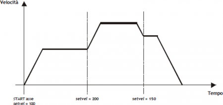
To simplify the calculation of the absolute positions of the master and the slave It is assumed that the master is moving at a constant speed whereby the axes positions can be represented in a Cartesian diagram Speed / Time. Below is a simple example of compiling the “cam table”.
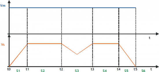
In order to can run a cam as in the example, you have to fill in the “cam table” as follows:
| Sector | CodeG | CodeQm | CodeQs | |
|---|---|---|---|---|
| S1 | 132 | 100 | 50 | Acceleration sector with Vs = Vm at the end of the sector |
| S2 | 133 | 200 | 200 | Intermediate sector at constant speed |
| S3 | 134 | 160 | 120 | Compensation sector with initial velocity = final velocity |
| S4 | 133 | 150 | 150 | Intermediate sector at constant speed |
| S5 | 135 | 90 | 45 | Deceleration sector with Vs = 0 at the end of the sector |
| S6 | 136 | - | - | Finish command cam |
QEM is available to help customers in the of the “cam table” compilation.
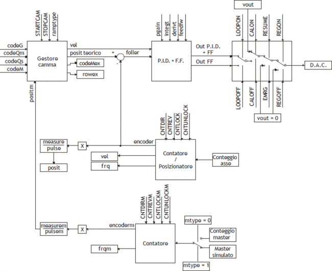
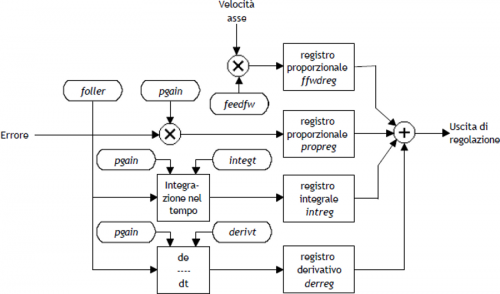
The device can be divided into two main parts:
-
A slave axis positioner with trapezoidal or selectable planetary ramps.
-
Analog cam generator.
Basic block diagram is as follows:
0.2 Installation
0.2.1 Device declaration in the configuration file (.CNF)
In the configuration file (.CNF), the BUS section must be declared so that they are present the hardware resources required for the implementation of the device CAMMING4. There must be at least two bidirectional counter and a 16-bit resolution analog output. In the INTDEVICE section of the .CNF file must be to add the following definition:
;-------------------------------
; Internal device declaration
;-------------------------------
INTDEVICE

<nome_device>  CAMMING4  TCamp  CountS  CountMA  CountMB  IntL  IAZero IntLM  IAZeroM  InG  InGInt  IoutA  Out
Where:
| INTDEVICE | Is a keyword indicating the beginning of the definition of internal device. |
| device_name | Is the device name. |
| CAMMING4 | Is the keyword that identifies the device described in this document. |
| TCamp | Sample time device (1÷250 ms). |
| CountS | Bidirectional counter Slave address |
| CountMA | Bidirectional counter Master address “A” |
| CountMB | Bidirectional counter Master address “B” |
| IntL | Number of the interrupt line dedicated to the encoder zero pulse Slave during the activity phase of presets. Allowed values: 1÷8 (to prevent the device uses this resource, Enter the X character). |
| IAZero | Slave zero pulse enable input (to prevent the device uses this resource, Enter the X.X character) |
| IntLM | Number of the interrupt line dedicated to the Master encoder zero pulse during the research phase of presets. Allowed values: 1÷8 (to prevent the device uses this resource, Enter the X character). |
| IAZeroM | Enable input zero-pulse master (to prevent the device uses this resource, Enter the X.X character) |
| InG | Entry for generic function as described in the section of the table input configuration (to prevent the device uses this resource, Enter the X.X character) |
| InGInt | Number of the interrupt line dedicated to a generic function as described in the section of the table input configuration. Allowed values: 1÷8 (to prevent the device uses this resource, Enter the X character). |
| IoutA | Hardware address of the DAC from analog output Slave. |
| Out | Output for generic function as described in section output configuration table (to prevent the device uses this resource, Enter the X.X character) |
0.2.1.1 Example
;---------------------------------
; Internal device declaration
;---------------------------------
INTDEVICE
AxisX  CAMMING4  2  2.CNT01  2.CNT02  1.CNT01  1  2.INP01  2  2.INP02  2.INP03  5  2.AN01  2.OUT01
Application example
You take as an example a CAMMING4 device configured as in the START-UP and with parameterisation of the axis (set-up) already written.
The task is first initialized the device and then run a interrupt input which shows its status on an exit.
The task will be carried out:
;-------------------------------------
; CAMMING4 device management
;-------------------------------------
INIT AxisX                      : Initializes the axis
WAIT AxisX:st_init              ; Wait until the axle is initialized
LOOPON AxisX                    ; Hooks the control loops
WAIT AxisX:st_loopon            ; Wait for the axis has hooked the
                                ; control loops
CALOFF AxisX                    ; Exit from calibration
                                ; of the axis
WAIT NOT AxisX:st_cal           ; Wait until the device is not in
                                ; calibration
CNTUNLOCK AxisX                 ; Unlocks the master counter
WAIT NOT AxisX:st_cntlock       ; Wait until the counter master is
                                ; unlocked
CNTDIR AxisX                    ; Sets the right direction of increase
                                ; slave counter
WAIT NOT AxisX:st_cntrev        ; Wait until the slave counter is
                                ; set in the sense of increase
CNTUNLOCKM AxisX                ; Unlocks the master counter
WAIT NOT AxisX:st_cntlockm      ; Wait until the counter master is
                                ; unlocked
CNTDIRM AxisX                   ; Sets the right direction master
                                ; counter increment
WAIT NOT AxisX:st_cntrevm       ; Wait until the counter master is
                                ; set in the sense of increase
REGON AxisX                     ; Unlock the adjusting
WAIT NOT AxisX:st_regoff        ; Wait for the regulation unlocking

MAIN:

IF AxisX:st_int                 ; If the interrupt line is active
  AxisX:funOut = 2              ; activates output
ELSE
  AxisX:funOut = 1              ; disables the output
ENDIF

ENDIF                           ; END

WAIT 1
JUMP MAIN
END
0.2.2 Calculation of the resolution
The CAMMING4 device lets the installer can work with unfinished encoder resolutions by setting the data as space covered in a round encoder (measure) and number of pulses/Rev encoder (pulse).
The relationship between the measure and pulse is the encoder resolution and must have values between 1 and 0.000935.
Definitions:
-
The measure paramenter is placed in units without decimal points (for example 100.0 millimeters is inserted 1000 tenths of a millimeter).
-
The pulse parameter is inserted 4 encoder bitrate (for example if connected an encoder with 1024 pulses round, is inserted 4096, If the measure is calculated on a encoder round).
Example:
You have to control a rotating table that have the accuracy of 0,1° with the 1024 pulses round encoder mounted directly to the motor; you will set the following values:
measure = 3600
pulse = 4096
0.2.3 Decimal point
If for the selected unit of measure is also provided for the presence of a decimal point positions must be represented as an integer and represent space on the drive measurement without decimal point. The resolution must be calculated using the same method and in the parameter measure the magnitude without decimal point. The decimal point will then be inserted into the representation of the value-time viewers (ex. as properties in the HMI). This parameter can take 0÷3 values.
0.2.4 Velocità
The speeds are always expressed in whole units of measure in the unit of time choice. From this it emerges that the device must know the location of the decimal point of the unit of measure and this is done with the decpt parameter.
0.2.5 Main controls
This section describes only the use of a number of some commands; for descriptions of all the set commands, refer to the following chapters.
The two main controls are what give start and break execution of cam: STARTCAM and STOPCAM. There are also a series of commands dedicated to emergency response, the loop control, START and STOP the axis.
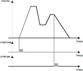
0.2.5.1 STARTCAM
The STARTCAM command, the slave axis attaches to master and will follow the trend described in the cam always starting from the first sector. You cannot take a STARTCAM during the execution of the (st_camex = 1) cam; ihis control is left to the programmer.
The cam will pop out automatically if it encounters a END instruction or you can stop it in flight by using the STOPCAM.
0.2.5.2 STOPCAM
If the cam is running (st_camex = 1), Once received the STOPCAM command the slave axis is released immediately by the master, brings his speed to zero following the deceleration ramp set (tdec parameter) and remaining in reaction to space. The deceleration ramp is asynchronous with respect to the master.
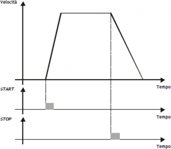
0.2.5.3 START
If the cam is running (st_camex = 1), Once received the STOPCAM command the slave axis is released immediately by the master, brings his speed to zero following the deceleration ramp set (tdec parameter) and remaining in reaction to space. The deceleration ramp is asynchronous with respect to the master.
0.2.5.4 STOP
If during the placement (not during the execution of a cam) you must stop the axis with a deceleration ramp, It will simply give the STOP command the axis decelerates to a stop with the ramp in the tdec parameter.
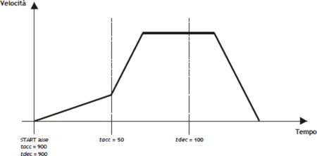
0.2.6 Change speed and moving ramp time
When positioning it is possible to vary the speed of the axis without affecting the location to get to. This can lead to an increase or a decrease in velocity, even in several places of the same positioning. This is accomplished with new writing in the setvel parameter. No gear is always available except during the deceleration ramp and is reported (st_chvel = 1)
When positioning can be varied even acceleration/deceleration times. For example, the device can start a placement at a rate very short and once they reach the speed set, varied tacc parameter and executed a change of speed with a very long ramp.
For special applications and trapezoidal ramps, ramp time can be varied even during a change of speed, in this case the new time is put into execution immediately.
0.2.6.1 EMRG
This command puts the axis in emergency conditions; the st_emrg state is set to one. If the emergency command is sent to the axis during a placement, movement is stopped without deceleration ramp, the analog output will be set to zero volts and you dropped the reaction of space. If the cam is active (st_camex = 1), the movement is interrupted without deceleration ramp, the analog output will be set to zero volts, space reaction is released and the cam (st_camex = 0).
With st_emrg = 1 (emergency condition), you cannot move the axis.
0.2.6.2 RESUME
This command will reset the emergency condition; the axis comes in reaction to space and waits for a command to be able to move (does not automatically resume interrupted positioning).
0.2.6.3 LOOPOFF
The LOOPOFF command removes the reaction of space without stopping the axis. With st_loopon = 0 the axis handling axis commands but accepts all placements will be performed without reaction of space. A placement made reaction loop-free is comparable to a positioning run without proportional gain (is not guaranteed to arrive in position).
0.2.6.4 LOOPON
The LOOPON command closes the ring of space without stopping the axis. With st_loopon = 1 the axis is moved using the P.I.D. control features.
Following is a table summarizing the conditions necessary for the axis in reaction to space and to perform placements.
| Loopon | Emrg | Space reaction | Possibility of movement |
|---|---|---|---|
| YES | NO | YES | YES |
| YES | YES | NO | NO |
| NO | NO | NO | YES |
| NO | YES | NO | NO |
0.2.7 Description of epicycloidal motion
The epicycloidal motion is used to move the axes without sudden variations of speed. The time of positioning of an axis moved by trapezoidal ramps is the same compared to the same axis moved by epicycloidal ramps, but ramps vary the shear rate (acceleration) with up to half of the ramp itself.
For comparison shows the difference of the development of the acceleration in the two cases: with linear ramp (trapezoidal) and with ramp reducers.
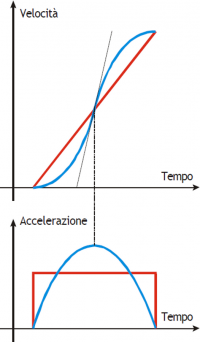
The same goes for the deceleration ramp.
Epicycloidal movement has the ability to behave in different ways in the event of a reduction in profile (rtype) and in the case of stop during acceleration (stopt) If the cam is not running (st_camex = 0).
0.2.8 Profile reduction
 | The profile reduction is used only if you are doing a placement and not if you're running a cam (st_camex = 0). |
|---|
If the cam is not running (st_camex = 0) and space to go is less than that which allows to reach the speed set by the acceleration and deceleration ramps, you pass in the phase called “profile reduction”.
You can keep fixed the time of ramps, decreasing gradients of the ramps and the speed in proportion (rtype parameter set to 0).
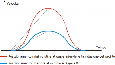
You can also decrease the time of the ramps while maintaining the gradient of constant acceleration and decrease speed in proportion (rtype parameter set to 1).
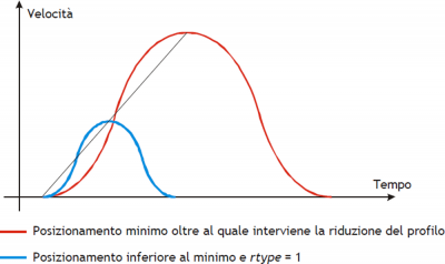
With the rtype parameter set to 0 xtend considerably the time needed to placements with loss of productivity of the machine, instead of setting it to 1 in case of short placements shorter, but keeping the constant gradient you lose the beneficial effect of the epicycloidal action.
0.2.9 Type of stop during acceleration ramp
| The type of stop while the ramps is only used if you are doing a placement and not if you're running a cam (st_camex = 0). |
|---|
In the event that the cam is not running (st_camex = 0) and we should curb the axis during acceleration with STOP commnand You must choose whether to complete the flight, or if you want to abort the flight and consequently change the epicycloidal action.
In case you set the stopt parameter to 0 is first completed the acceleration ramp and then performed the deceleration ramp.
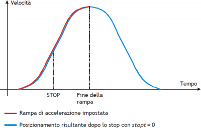
In case you set the parameter stopt to 1 stops the acceleration ramp and started immediately the deceleration ramp set.
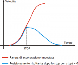
You immediately notice that there is a substantial difference between the setting of stopt to 0 or to 1.
To make the choice of what type of stop use, one must remember that in case of emergency stop the emergency command exists that instantly locks and without ramp positioning.
0.2.10 Analogue output calibration
| Before starting actual placements you must make sure that electrical connections and mechanical appliances have not cause malfunctions. |
|---|
For the management of the axis, the device uses a ± 10 V analogue output range and 16-bit signed resolution; this calibration function with analog output can be driven with a constant value in order to test links and functionality.
0.2.10.1 Preliminary motion
-
Remove the emergency condition with the RESUME command.
-
The state st_emrg = 0
-
Enable calibration axis status with the CALON command; the st_cal state must therefore be 1.
-
You can now set the analog voltage with the vout parameter; the value is expressed in tenths of volt (-100 ÷ 100 = -10 ÷ 10 V). It is recommended to introduce low values (5, 10, 15… equal to 0.5, 1, 1,5 V).
-
When the axis is moving the frq parameter indicates the frequency in Hz of the sphases of the transducer.
-
The posit parameter that displays the position varies indicating the space covered by the axis. If setting a positive voltage will count decrements, it is necessary to invert the phases of the transducer or reverse the direction in driving.
-
You can reverse the direction of the count using the CNTREV command.
-
If with output voltage to zero the axis is not stationary, adjust the offset parameter to correct the voltage until movement does not stop. The input value (each bit corresponds to 0.3 mV), will be added algebraically to the value of the analogue output; This operation allows to compensate for any drift of electronic component, both in QMOVE outgoing and to driver input. The value is expressed in bits with sign.
For an optimal result of calibration this operation must be performed with the system to temperature capacity. -
To disable calibration status send the CALOFF command.
-
The state st_cal = 0
0.2.10.2 Output setting
The device generates the voltage value of the analogue output based on a ratio between the maximum velocity of the axis and the maximum output voltage. Proportionality is obtained with the maxvel parameter, that represents the speed of the axis on the analog voltage (10 V). Obviously the axle must behave symmetrical analog voltage to zero, therefore the speed must be the same on both the positive and negative voltage at maximum.
Prior to determining the value of maximum velocity,we must establish the unit of time to use for the representation of the speed in the device; the unitvel parameter defines the unit of time of speed (Um/min or Um/s).
0.2.10.3 Theoretical method for the determination of the maximum speed
The theoretical method is a calculation that was performed on the basis of maximum motor speed. Once established the maximum revolutions per minute that are declared in the motor, We get the maximum velocity is expressed in the unit of measure the unit of time chosen. Enter the maximum velocity value calculated in the maxvel parameter.
0.2.10.4 Practical method for determining the maximum speed
The practical approach is based on the reading of the speed detected by the device in the vel parameter, giving the drive a known voltage. To provide the voltage to drive the device should be placed in a position of calibration as described in the previous paragraph. If the system permits, give the drive a voltage of 10 V and read the speed value in the vel parameter. If, on the other hand, provides a part of the output voltage (1, 2, … 5 V), calculate the maximum velocity with a proportion.
Enter the value found by maximum velocity in the maxvel parameter.
0.2.11 Movement
| Before handling the Board, check the proper operation of emergency equipment and protection. |
|---|
The procedures described here have allowed us to complete the first phase of parameterizing device. Now you can run simple movement of the axis.
-
Move the axis in a position whereby it can fulfill a certain area without touching the maximum and minimum quota limits.
-
Set the current position to zero axis, by setting the parameter posit = 0.
-
Set up the parameters that define the position of the limit switches software: minpos = 0 and maxpos the value of the maximum stroke of the axis.
-
Set the parameter that defines the axis time to reach the maximum speed tacc = 100. This parameter is expressed in hundredths of a second (100 = 1 sec.)
-
Set the speed of positioning with the setvel parameter.
-
Set the target quota with the setpos parameter.
-
Set the parameter feedfw = 1000 (100%)
-
If the device is in emergency state (st_emrg = 1) give the RESUME command.
-
Start positioning with the START command. To stop the movement give the EMRG command.
This first movement was done without speed feedback space. The placement may have been executed with some error introduced by the non-linearity of the components or an imperfection in the calibration of the maximum speed. Enabling space feedback this error goes away.
0.2.12 PID+FF Calibration
The placement runs in the preceding paragraph has been made without considering any position errors.
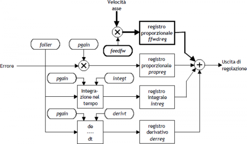
To check the correct position of the axis in continuously and automatically, You must have the position feed-back; for this reason introduces the control algorithm PID + FF including proportional shares, integral, derivative and feed-forward; the value of the analog output is given by the summation of feed forward, proportional, derivative and integrative actions.
This section describes a series of actions to adjust the parameters that affect this control.
In order to achieve a satisfactory adjustment is sufficient to use only the actions feedforward and proportional; integral and derivative actions are used only for adjustments under special conditions.
0.2.12.1 Feed forward action
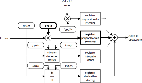
The feed-forward helps make the system more ready on placements, providing the analogue output voltage proportional to the theoretical speed of positioning. In practice it is the component which you performed the placements of the previous chapter.
The contribution of this action can be adjusted with the parameter feedfw; This parameter is expressed as 1/1000 speed theoretical portion; so, to introduce such as 98.5% you must set 985 (thousandths).
0.2.12.2 Proportional action
This action provides an output proportional to the instantaneous axis position error. The extent of the proportional action is defined by the pgain parameter that defines the sensitivity of the system.
The pgain parameter is introduced in thousandths; the unit value of the gain (1000) provides an analog output to maximum value (10 V) concerning the maximum speed error. For maximum speed error means the space taken by axis - at the maximum speed - for the duration of the sampling time of the device.
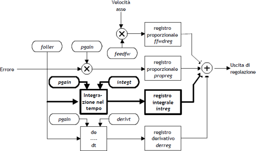
0.2.12.3 Integral action
Integrates the position error of the system over time set in integt parameter updating the release until the error is not canceled. If it drops the integration time of the error, the system retrieves the error faster, but can become unstable, tending to swing.
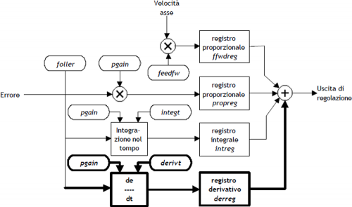
0.2.12.4 Derivative action
Anticipates the change of the motion of the system by delete the overshoot positioning. The size of change is calculated over time set in derivt parameter. When the time of derivation of error is higher, more faster is the transient error recovery system, but if you enter a value that is too high the system becomes unstable, tending to fluctuate.
0.2.13 Movement application
In order to move the slave axis must first declare the parameterization of axis. Once this stage is thought to want to move the slave axis with jog manuals using Inp01 input for moving forward and the Inp02 input to move it back.
As an example, consider a device configured as in START UP. The task is first initialized the device and then run the manual jog.
;----------------------------------------------------
; Manual jog management
;----------------------------------------------------

INIT AxisX                          : Initializes the axis
WAIT AxisX:st_init                  ; Wait until the axle is initialized
LOOPON AxisX                        ; Hooks the control loops
WAIT AxisX:st_loopon                ; Wait for the axis has hooked the
                                    ; control loops
CALOFF AxisX                        ; Exit from calibration
                                    ; of the axis
WAIT NOT AxisX:st_cal               ; Wait until the device is not in
                                    ; calibration
CNTUNLOCK AxisX                     ; Unlocks the master counter
WAIT NOT Axis:st_cntlock            ; Wait until the counter master is
                                    ; unlocked
CNTDIR AxisX                        ; Sets the right direction of increase of
                                    ; slave counter
WAIT NOT AxisX:st_cntrev            ; Wait until the counter is slave
                                    ; set in the sense of increase
CNTUNLOCKM AxisX                    ; Unlocks the master counter
WAIT NOT AxisX:st_cntlockm          ; Wait until the counter master is
                                    ; unlocked
CNTDIRM AxisX                       ; Sets the right direction of increase of
                                    ; master counter
WAIT NOT AxisX:st_cntrevm           ; Wait until the counter master is
                                    ; set in the sense of increase
REGON AxisX                         ; Unlock the adjusting
WAIT NOT AxisX:st_regoff            ; Wait the unlocked of the regulation
MAIN:

IF Inp01 AND Inp02                  ; If the Inp01 and the
                                    ; Inp02 inputs are active
  IF NOT AxisX:st_still             ; If the axis is not stationary
    STOP AxisX                      ; Stop the axis
  ENDIF
ENDIF

IF Inp01 AND NOT Inp02              ; I the Inp01 input is
                                    ; active and the
                                    ; Inp02 input are deactivate
  IF AxisX:st_still                 ; If the axis is stopped
    AxisX:setvel=AxisX:maxvel/10    ; I set the speed of
                                    ; manual movement
    MANFW AxisX                     ; Forward manual
  ENDIF
ELSE
  IF NOT Inp02                      ; If the Inp02 input
                                    ; is deactive
    IF NOT AxisX:st_still           ; If the axis is not stationary
       STOP AxisX                   ; Stop the axis
    ENDIF
  ENDIF
ENDIF

IF Inp02 AND NOT Inp01              ; If the Inp02 input
                                    ; is active and the Inp01
                                    ; input is deactivate
  IF AxisX:st_still                 ; If the axis is stopped
    AxisX:setvel=AxisX:maxvel/10    ; I set the speed of
                                    ; manual movement
    MANBW AxisX                     ; Backward manual
  ENDIF
ELSE                                ; Otherwise
  IF NOT Inp01                      ; If the Inp01 input is
                                    ; deactive
  IF NOT AxisX:st_still             ; If the axis is not stationary
     STOP AxisX                     ; Stop the axis
  ENDIF
ENDIF                               ; END

WAIT 1
JUMP MAIN
END
0.2.14 The sectors structure
The device does not have inside datagroup or array data where you can contain various types of cams, so, if you need to manage different cams according to the type of work, you must place the CPU tools and download data on the device whenever there is a need.
0.2.14.1 Example:
This example handles the cam programming with data entered in the second program of a datagroup. The device is configured as described in the startup.
;--------------------------------------------------
; Configuration file
;--------------------------------------------------

;--------------------------------------------------
; Global Variables
;--------------------------------------------------

GLOBAL
gfProgram F ;Enabling cam programming

;--------------------------------------------------
; System Variables
;--------------------------------------------------

SYSTEM
sbPuntProg B ;Program number that you want to put into execution

;--------------------------------------------------
; Datagroup Variables
;--------------------------------------------------

DATAGROUP
dgCamma

DATAPROGRAM 10 ;10 available programs
ddlCode L ;program code

STEP 128 ;128 available program step
ddbCodeG B ;G code
ddlCodeQs L ;Qs code
ddlCodeQs L ;Qm code
ddlCodeM L ;M code
ddlCodeQma L ;auxiliary Qm code
ddlCodeQsa L ;auxiliary Qs code

;--------------------------------------------------
; Cam programming tasks
;--------------------------------------------------
MAIN:
   .
   .
   sbPuntProg = 2 ;Setting the program pointer
   .
   .

;--------------------------------------------------
; Programming of the CAMMING2 device
;--------------------------------------------------
IF gfProgram
   AxisX:codeG1     = ddbCodeG [sbPuntProg , 1] ;Sector 1
   AxisX:codeQm1    = ddlCodeQm [sbPuntProg , 1] ;Sector 1
   AxisX:codeQs1    = ddlCodeQs [sbPuntProg , 1] ;Sector 1
   AxisX:codeQma1   = ddlCodeQma [sbPuntProg , 1] ;Sector 1
   AxisX:codeQsa1   = ddlCodeQsa [sbPuntProg , 1] ;Sector 1
   AxisX:codeM1     = ddlCodeM [sbPuntProg , 1] ;Sector 1
   AxisX:codeG2     = ddbCodeG [sbPuntProg , 2] ;Sector 2
   AxisX:codeQm2    = ddlCodeQm [sbPuntProg , 2] ;Sector 2
   AxisX:codeQs2    = ddlCodeQs [sbPuntProg , 2] ;Sector 2
   AxisX:codeQma2   = ddlCodeQma [sbPuntProg , 2] ;Sector 2
   AxisX:codeQsa2   = ddlCodeQsa [sbPuntProg , 2] ;Sector 2
   AxisX:codeM2     = ddlCodeM [sbPuntProg , 2] ;Sector 2

   .
   .

   AxisX:codeG128 = ddbCodeG [sbPuntProg , 128] ;Sector 128
   AxisX:codeQm128 = ddlCodeQm [sbPuntProg , 128] ;Sector 128
   AxisX:codeQs128 = ddlCodeQs [sbPuntProg , 128] ;Sector 128
   AxisX:codeQma128 = ddlCodeQma [sbPuntProg , 128] ;Sector 128
   AxisX:codeQsa128 = ddlCodeQsa [sbPuntProg , 128] ;Sector 128
   AxisX:codeM128 = ddlCodeM [sbPuntProg , 128] ;Sector 128

   gfProgram = 0
ENDIF
0.3 The sectors
The CAMMING3 device manages cam sectors scheduled incremental, within which shows the space ahead from the master and the space to take the slave. A cam is composed of several sectors which may be accelerating, decelerating, or dedicated to operations such as speed change, for example, the power factor correction counter or loop cam.
Each sector of the cam must contain information about:
-
codeG sector type
-
codeQm master quota (Attention: insert only positive values)
-
codeQs slave quota
-
codeQma auxiliary master quota (Attention: insert only positive values)
-
codeQsa auxiliary slave quota
-
codeM Code of general use, which is indicated by the codeMex variable. Typically contains the tools the state, cam special states, etc.
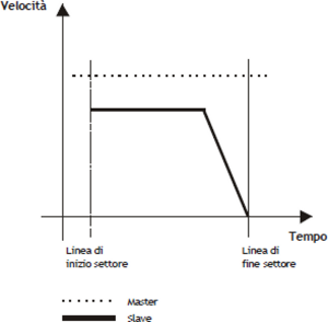
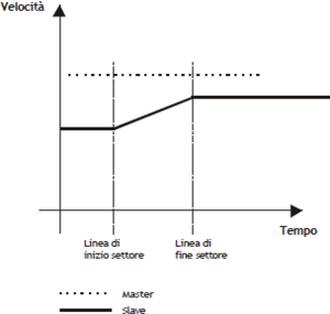
0.3.1 The sector of acceleration
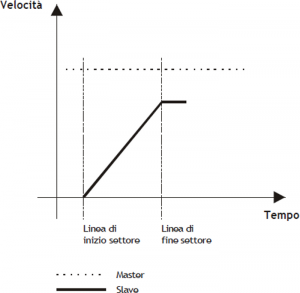
The sector of acceleration is used with slave axis stopped (slave zero speed, regardless of the speed of the master); at the end of the sector the speed of the slave is the same as that of the master.
Typical cases of acceleration are shown in A, B, C and D pictures.
In the example of A picture, at the end of the sector to be equal to that of the speed of the slave master; the law that binds the space master and slave is:
Slave space = 1/2 Master space
More smaller will be the space master considered more greater will be the acceleration gradient of the slave, which we can derive from the formula:
Time acc. slave = Master space in the sector of acc. / Maximum master speed
| In case you are facing this kind of acceleration we recommend using codeG = 132 code. |
|---|
| Picture A |
 |
Programming example:
-
codeG 132
-
codeQm Master space
-
codeQs Slave space
-
codeQma Not use
-
codeQsa Nont used
-
codeM generic code
| If you wish to use the planetary ramps, we recommend the use of the code codeG = 232. |
|---|
In case you want to use the epicycloidal ramps to accelerate with the same functions described for 132 sector, simply program the sector as described above and planning codeG = 232.
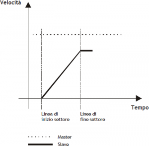
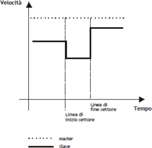
In the example of B picture, at the end of the field the speed of the slave is in proportion to the speed of the master (the proportion will be called K), the law that binds the master and slave space space is:
Slave space = K/2 Master space
More smaller will be the space master who considers, more greater will be the acceleration gradient of the slave, that we can derive from the formula:
Time of slave acc. = Master space in the acc. sector / Maximum speed master
| In case you are faced with this type of acceleration is required using codeG = 131 code. |
|---|
| Picture B |
 |
Programming example:
-
codeG 131
-
codeQm Master space
-
codeQs Slave space
-
codeQma Not used
-
codeQsa Not used
-
codeM generic code
| If you wish to use the epicycloidal ramps, we recommend using codeG = 231 code. |
|---|
In case you want to use the epicloidal ramps to accelerate with the same functions described for 131, simply program the field as described above and planning codeG = 231.
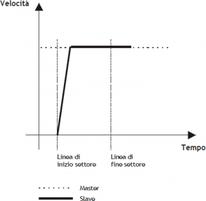
In the picture C example, more acceleration are needed, and you cannot set Master/Slave quotes of finished value. 150 sector is basically the sum of two sectors: 131 and 133. This sector is used when you know the spaces next to the field of acceleration and you want one slave very small accelerative space, even less than the unit of measurement.
The sector 150 uses the following parameters:
-
codeG : sector code (150)
-
codeQma : master space within which the slave must be at a certain speed, which we call the synchronization.
-
codeQm and codeQs : where the division indicates the relationship between the slave and master (synchronization report). These spaces will be made after accelerative section.
-
codeQsa : indicates the space into encoder pulses that must take the slave in the acceleration phase to reach the sync speed.
More smaller will be the space master who considers himself, more greater will be the acceleration gradient of the slave, who do we get from the formula:
Time of Slave acc. = Master space on the acc. sector / Maximum master speed
| In case you are faced with this type of acceleration is required using code codeG = 150. |
|---|
| Picture C |
 |
Programming example:
-
codeG 150
-
codeQm Master Space
-
codeQs Slave Space
-
codeQma Master Space in acceleration
-
codeQsa Slave SPace in acceleration (bit * 4)
-
codeM generic code
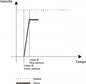
In the picture D example, more acceleration are needed, and you cannot set Master/Slave quotes of finished value. 152 sector is basically the same the sector 131. This sector is used when you know the synchronization report and you want one slave very small, even smaller than the space inertial measurement unit.
152 sector takes advantage of the following parameters:
-
codeG : sector code (152)
-
codeQma : master space within which the slave must be at a certain speed, which we call the synchronization.
-
codeQm and codeQs : where the division indicates the relationship between the slave and master (synchronization report).
-
codeQsa : indicates the space into encoder pulses that must take the slave in the acceleration phase to reach the sync speed.
More smaller will be the space master who considers himself, more greater will be the acceleration gradient of the slave, who do we get from the formula:
Time of Slave acc. = Master space on the acc. sector / Maximum master speed
| In case you are faced with this type of acceleration is required using code codeG = 152. |
|---|
| Picture D |
 |
Programming example:
-
codeG 152
-
codeQm Master Coefficient
-
codeQs Slave Coefficient
-
codeQma Master Space in acceleration
-
codeQsa Slave Space in acceleration (bit * 4)
-
codeM generic code
| If you wish to use the epicycloidal ramps, we recommend the use of the code codeG = 252. |
|---|
In case you want to use the epicycloidal ramps to accelerate with the same functions described for 152 sector, simply program the sector as described above and planning the code codeG = 252.
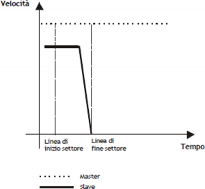
0.3.2 The deceleration sector
In case you need to stop the slave axis (regardless of its speed), remaining engaged with the cam (zero speed regardless of the speed of the master), it can be used the deceleration sector.
In the picture E example, at the end of the sector, the speed of the slave will be zero; la law that binds the space master and slave (the proportion between the master and the slave speed will be called K) is:
Slave space = K/2 Master space
More smaller is the space master who considers himself, more greater will be the degree of deceleration of the slave, which you can obtain from:
Time of Slave dec. = Master space in the dec. sector / Maximum master speed
| In case you find a this deceleration is obligatory the use the code codeG = 135. |
|---|
| Picture E |
 |
Programming example
-
codeG 135
-
codeQm Master space
-
codeQs Slave space
-
codeQma Not used
-
codeQsa Not used
-
codeM generic code
| If you wish to use the epicycloidal ramps, we recommend the use the code codeG = 235. |
|---|
In case you want to use the epicycloidal ramps to accelerate with the same functions described for the sector 135, simply program the field as described above and planning codeG = 235.
In the picture F example, syou need strong deceleration, and you cannot set Master/Slave dimensions of finished value. The 151 sector is basically the sum of two sectors: 133 and 135. This sector is used when you know the spaces before the deceleration area and want a space decelerativo slave very small, even smaller than the unit of measurement.
151 sector makes use of the following parameters:
-
codeG : sector code (151)
-
codeQma : master space within which the slave must be from a certain speed, which we call the zero speed synchronization.
-
codeQm and codeQs : where the division indicates the relationship between the slave and master (synchronization report). These spaces are made before decelerative section.
-
codeQsa : indicates the space into encoder pulses that must cover the slave during deceleration.
More smaller is the space master who considers himself, more greater will be the degree of deceleration of the slave, which we can derive from the formula:
Time of Slave dec. = Master space in dec. sector / Maximum master speed
:^info:^In case you find a this deceleration is obligatory the use the code codeG = 151.
| Picture F |
 |
Programming example
-
codeG 151
-
codeQm Master space
-
codeQs Slave space
-
codeQma Master space decelerating
-
codeQsa Slave space in decelerating (bit * 4)
-
codeM generic code
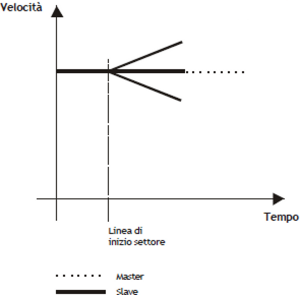
0.3.3 Speed change sector
| In order to do this operation there are two types of codes (codeG = 133 and codeG = 134) which differ only in the choice of the speed that you want to give to the slave at the end of the speed change sector. |
|---|
Speed change sector can be used:
-
Whenever the slave axis must reach speeds (nonzero), starting at a different speed (also non-zero).
-
Whenever the slave axis must maintain a constant speed.
In the example the speed of the slave is the same as that of the master (at the beginning of speed change sector). In case the speed is different you need to consider, in the follow formulas, the master and slave relationship of constant speed at the beginning of the sector.
The codeG = 133 provides that the speed of the slave at the end of the sector can be different from the initial and final speed of the slave (of end time sector), will depend exclusively on the master/slave relationship of spaces (see picture G).
We have three cases:
1)Master/slave relationship < 1 Speed of the slave at the end of the sector > of the master speed
2)Master/slave relationship = 1 Speed of the slave at the end of the sector = of the master speed
3)Master/slave relationship > 1 Speed of the slave at the end of the sector < of the master speed
The speed at the end of the sector is given by the formula:
Slave Speed = Master Speed + { [ 2 (Slave Space - Master Space) / Master Space ] x 100 } %
| Picture G |
 |
Programming example:
-
codeG 133
-
codeQm Master Space
-
codeQs Slave Space
-
codeQma Not used
-
codeQsa Not used
-
codeM generic code
| If you wish to use the epicycloidal ramps, we recommend the use the code codeG = 233. |
|---|
In case you want to use the epicycloidal ramps to accelerate with the same functions described for the sector 133, simply program the sector as described above and planning codeG = 233.
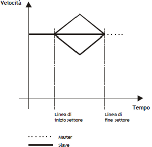
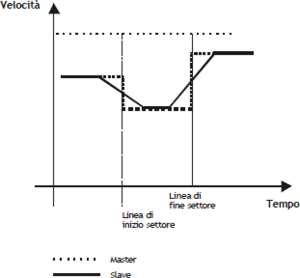
The codeG = 134 provides that the speed of the slave at the end of the sector is the same as the speed at half the slave sector will depend exclusively on the relationship of the master/slave spaces (see picture H). We have three cases:
1) Master/slave relationship < 1 Speed of the slave in the middle of the sector > of the master speed
2) Master/slave relationship = 1 Speed of the slave in the middle of the sector = of the master speed
3) Master/slave relationship > 1 Speed of the slave in the middle of the sector < of the master speed
The speed in the middle of the sector will be given by the formula:
Slave Speed = Master Speed + { [ 2 (Slave Space - Master Space) / Master Space ] x 100 } % x (Master Speed)
| Picture H |
 |
Programming example:
-
codeG 134
-
codeQm Master Space
-
codeQs Slave Space
-
codeQma Not used
-
codeQsa Not used
-
codeM generic code
| If you wish to use the epicycloidal ramps, we recommend the use the code codeG = 234. |
|---|
In case you want to use the epicycloidal ramps to accelerate with the same functions described for the sector 134, simply program the sector as described above and planning codeG = 234.
If you are programming a sector 133, 134, 233 or 234 with master and slave space to 0, it is considered as a non-operating sector (codeG = 130).
In the picture I example, wants to change speed to the slave, and it is not possible to set a Master/Slave relationship of finite value. The sector 153 is the same as sector 133. This sector is used when you know the synchronization report and you want one slave very small inertial space, sometimes even lower than the unit.
The sector 153 uses the following parameters:
-
codeG : sector code (153)
-
codeQma : master space within which the slave must be at a certain speed, which we call the synchronization.
-
codeQm and codeQs : whose division indicates the ratio between the slave and master (rapporto di sincronizzazione).
-
codeQsa : the device indicates the space in which the slave route encoder pulses to reach the sync speed after acceleration phase.
| In case you are using this type of transmission speed, we recommend the use of the code codeG = 153. |
|---|
| Picture I |
 |
Programming example:
-
codeG 153
-
codeQm Master Coefficient
-
codeQs Slave Coefficient
-
codeQma Space Master in acceleration
-
codeQsa Space Slave in acceleration (bit * 4)
-
codeM generic code
| If you wish to use the epicicloidal ramps, we recommend the use of the code codeG = 253. |
|---|
In case you want to use the epicycloidal ramps to accelerate with the same functions described for the sector 153, simply program the sector as described above and planning codeG = 253.
In the example of L picture, you want to bring the slave at a speed without having to run a connection ramp. The sector 154 unlike all other, forces the initial velocity equal to the final speed while maintaining a constant speed between two points. This sector can be used as the starting sector of the cam (starting without acceleration), as intermediate sector or final sector (stop without ramp).
The sector 154 uses the following parameters:
-
codeG : sector code (154)
-
codeQma : Softening sector type
-
codeQm and codeQs : whose division indicates the relationship between the slave and master (synchronization relationship). These spaces are performed during the sector.
-
codeQsa : if set to 0 indicates that the next sector is an area of movement, if set to 1 indicates that the next sector does not provide for movement (deceleration with zero ramp).
| In case you have to use this type of movement is obligatory the use of the code codeG = 154. |
|---|
| Picture L |
 |
Programming example:
-
codeG 154
-
codeQm Master Space
-
codeQs Slave Space
-
codeQma Softening sector type
-
codeQsa
0 = next sector of movement
1 = stationary axis in the next sector
2 = Gearing axis -
codeM generic code
0.3.3.1 Softening sector type
From the graph in Picture L speed steps can be seen in the change between one sector and the subsequent. To eliminate the steps has been included exchange softening sector function which plan to put a ramp smoothing between the two sectors so as to make it less “rough” switching between one sector and the subsequent.
Programming the softening can be done by simply entering in codeQma, taking advantage of the half, a third, a fourth or a fifth of the smallest sector. Softening only runs between two adjacent 154 sectors, without having put no codeG different (counter change, jump, etc.).
| Picture M |
 |
The codeQma has the following meaning:
-
0 = No softening
-
1 = Soften 1/2 smaller sector
-
2 = Soften 1/3 smaller sector
-
3 = Soften 1/4 smaller sector
-
4 = Soften 1/5 smaller sector
In case you want to use the ramps to epicycloidal speed variations, respect the same functions described for 154 sector, simply program the sector as described above and use the code G=254.
0.3.3.2 Sector set as "Gearing"
To schedule a sector as gearing you must program the parameters as described below:
codeG1 = 154
codeQma1 = 0
codeQsa1 = 2
codeQm1 = numerator of the speed ratio
codeQs1 = denominator of thespeed ratio
Once given the command of the Startcam, the only editable values are codeQs and codeQsa, If other values are changed with the cam running could result in the error 5 and the device goes into emergency.
The relationship between codeQm and codeQs points, respectively, the Master/Slave relationship electric Gearing, and in particular this report can be changed dynamically (with cam running) acting only on the parameter codeQs. These parameters follow always the law of minimum space at sampling time (that is, the space made by the master in a sampling time of the device, must be less than the maximum speed set to codeQm), so, in order to avoid errors on the cam, it is better to set sufficiently high values; example, the ratio is 1:1 the values might be codeQm = 1000 and codeQs = 1000.
The new speed of the Slave due to the new ratio is reached immediately from the axis without any ramp, so if you want to have a smooth change of speed you should gradually change the relationship until you reach the desired.
If you set the value 0 or 1 on codeQsa you go on to the next sector (If you have not planned any sector later to stop the device simply give a Stop-cam).
The positm and posit variables (Master counter and Slave counter) are automatically given respectively to the value of codeQm and codeQs at the exact moment the value of variables exceeds the value set in CodeQm (postm) and CodeQs (to posit).
0.3.4 Trigonometric sectors
 | In a typical setup utilizing Q1-CPU-DA02 with 2 interpolated axis circularly more an tangent axis, the minimum acceptable sampling time is 4 milliseconds (3mS for the 3 devices CAMMING4 and 1mS for the simulated master). |
|---|
The CAMMING4 device can to manage the Slave axis with trigonometric sine, cosine or tangent type trends so that by combining multiple slave axes can move the axes carrying out circular interpolation, helical, kickbacks and all the movements of this type with the advantage that the limit on the number of axes to be handled is made solely by the sample time that you declare in the configuration of the application and which is directly proportional to the number of axes used
As we know from trigonometry, the Cartesian coordinates of a point belonging to a circle are representable by functions Y = R * sen(a) and X = R * cos(a).“
| Picture N |
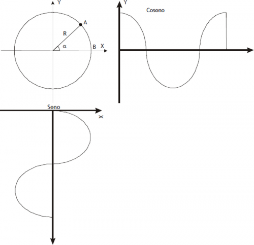 |
To realize circular interpolation between the X and Y axes you must tie the motion of the two axes of a single Master (also simulated). If the path traveled in space from point A to point B is an arc, we can state that in that space Master Slave axes X and Y must move as a function of RADIUS R and angle a. The trip speed of simulated master determines the speed of interpolation between the axes, i.e. the speed of a hypothetical point along the path in the XY plane.
The speed ratio between the Master and the Slave is at most 1. So, if you are using two Slave axes linked to the same Master, the maximum speed with which it moves the Master (simulated or not) is equal to the smallest of the two maximum speeds of two slaves axes. If this system adds a third axle Camming 4 utilizing the same simulated axis Master, this axis will always be directed on the tangent of the circle.
The following are examples of application:
codeG = 170 =⇒ Clockwise sine
codeG = 171 =⇒ Counterclockwise sine
codeG = 172 =⇒ Clockwise cosine
codeG = 173 =⇒ Counterclockwise cosine
codeG = 174 =⇒ Clockwise tangent
codeG = 175 =⇒ Counterclockwise tangent
codeG = 180 =⇒ Tangent axis power
In case you need to move the slave axis in breast function and you want to follow the trajectory than the clockwise direction of the circumference, you must use the codeG = 170. If you programmmin the positive value of the radius of the circumference (codeQm), runs the shortest arc, while if it is negative, the arc path is more longer.
Programming example
-
codeG 170
-
codeQm Radius of the circumference in units of measure
-
codeQs Displacement of the Slave axis X (device in programming)
-
codeQma Master space display executed in the sector in units of measure
-
codeQsa Displacement of the Slave axis Y (associated device)
-
codeM Generic code
In case you need to move the slave axis as a function of sine and you want to follow the trajectory than the counterclockwise circle, you must use the codeG = 171. If you programmmin the positive value of the radius of the circumference (codeQm), runs the shortest arc, and if it is negative, it is the longest arc path.
Programming example
-
codeG 171
-
codeQm Radius of the circumference in units of measure
-
codeQs Displacement of the Slave axis X (device in programming)
-
codeQma Master space display executed in the sector in units of measure
-
codeQsa Displacement of the Slave axis Y (associated device)
-
codeM Generic code
In case you need to move the slave axis as a function of the cosine and you want to follow the trajectory than the clockwise direction of the circumference, you must use the codeG = 172. If you programmmin the positive value of the radius of the circumference (codeQm), runs the shortest arc, while if it is negative, the arc path is longer.
Programming example
-
codeG 172
-
codeQm Radius of the circumference in units of measure
-
codeQs Displacement of the Slave axis X (device in programming)
-
codeQma Master space display executed in the sector in units of measure
-
codeQsa Displacement of the Slave axis Y (associated device)
-
codeM Generic code
In case you need to move the slave axis as a function of the cosine and you want to follow the trajectory than the counterclockwise circle, you must use the codeG = 173. If you programmmin the positive value of the radius of the circumference (codeQm), runs the shortest arc, while if it is negative, the arc path is longer.
Programming example
-
codeG 173
-
codeQm Radius of the circumference in units of measure
-
codeQs Displacement of the Slave axis X (associated device)
-
codeQma aster space display executed in the sector in units of measure
-
codeQsa Displacement of the Slave axis Y (device in programming)
-
codeM Generic code
In case you need to move the slave axis as a function of tangent and you want to follow the trajectory than the clockwise direction of the circumference, you must use the codeG = 174. If you programmmin the positive value of the radius of the circumference (codeQm), runs the shortest arc, while if it is negative, the arc path is longer.
Programming example
-
codeG 174
-
codeQm Radius of the circumference in units of measure
-
codeQs Slave axis movement
-
codeQma Master space display executed in the sector in units of measure
-
codeQsa Movement of the other Slave axis
-
codeM Generic code
In case you need to move the slave axis as a function of tangent and you want to follow the trajectory than the counterclockwise circle, you must use the codeG = 175. If you programmmin the positive value of the radius of the circumference (codeQm), runs the shortest arc, while if it is negative, the arc path is longer.
Programming example
-
codeG 175
-
codeQm Radius of the circumference in units of measure
-
codeQs Slave axis movement
-
codeQma Master space display executed in the sector in units of measure
-
codeQsa Movement of the other Slave axis
-
codeM Generic code
In case you need to re-adjust the Slave axis to retrieve any angular position error of axis tangent, that has shifted to the multivariate angular calculations, you must use the codeG = 180. In codeQs you should enter the difference in position of the axis to be recovered, expressed in units of measurement.
Programming example
-
codeG 180
-
codeQm Not used
-
codeQs Recovery value of the Slave axis in units of measure
-
codeQma Not used
-
codeQsa Not used
-
codeM Not used
0.3.4.1 Example of using sectors sine, cosine and tangent
You want to connect the starting point A to the ending point B with an arc of a circle with radius R.
We know that for 2 points pass 2 circles with radius R, so you have to make the choice of which of the 4 ch unit we want to go. The choice is made according to what's shown in Picture 0. With the terms AxisX and AxisY means devices that handle respectively the X and Y axes of the system.
| Picture O |
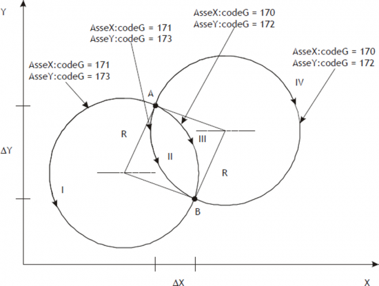 |
The arc between point A and point B can run through one of the four trajectories I, II, III, IV. Con R = 26, ?X = 15 e ?Y = 33 programming to get each of these trajectories is:
| Trajectory I | |||||||
|---|---|---|---|---|---|---|---|
| AxisX | AxisY | ||||||
| codeG | codeQm | codeQs | codeQsa | codeG | codeQm | codeQs | codeQsa |
| 171 | -26 | 15 | -33 | 173 | -26 | 15 | -33 |
| Trajectory II | |||||||
| AxisX | Axis | ||||||
| codeG | codeQm | codeQs | codeQsa | codeG | codeQm | codeQs | codeQsa |
| 171 | 26 | 15 | -33 | 173 | 26 | 15 | -33 |
| Trajectory III | |||||||
| AxisX | AxisY | ||||||
| codeG | codeQm | codeQs | codeQsa | codeG | codeQm | codeQs | codeQsa |
| 170 | 26 | 15 | -33 | 172 | 26 | 15 | -33 |
| Trajectory IV | |||||||
| AxisX | AxisY | ||||||
| codeG | codeQm | codeQs | codeQsa | codeG | codeQm | codeQs | codeQsa |
| 170 | -26 | 15 | -33 | 172 | -26 | 15 | -33 |
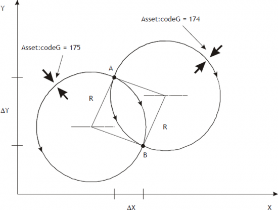
With the example above shows the relationship between the codeG (174, 175) parameters and codeQm paramenter the sectors that handle the axis tangent arcs of jointing circumference the starting point to the ending point B. With the term Asset means the device that handles the tangent axis. The example in Picture P shows the case longer trajectories; to choose shorter ones set codeQm = R while the meaning of codeG stays the same. The bold arrow represents the axis.
Given that it is assumed that the tangent axis is properly positioned at the beginning of each sector, No one does the distinction between left/right axis the direction of advancement but simply reserve two areas for clockwise and counterclockwise movements.
| Picture P |
 |
0.3.5 The Start sector synchronized to the Master
Many times there is a need to start the slave on the master known, but there is the possibility to connect to a proximity sensor. The only constraint is that the sector containing the codeG 160 must be the first sector of cam motion and cannot be placed in the loop. At the STARTCAM command, the st_camex state goes to 1 and the the movement of the Slave axis begins only at Master quota (expressed in units of measurement) set in the sector 160 and from there will follow the trend described in the following sectors.
If the STARTCAM command is given with the above-quota master count, is set the warning 9; under these conditions the Master counting must become less than the quota set for it to be in the right situation of the system.
You can't get into a sector with codeG = 160 coming from a jump or a loop cam (error 7).
Programming example:
-
codeG 160
-
codeQm STARTCAMMA quota expressed in units of measurement
-
codeQs Not used
-
codeQma Not used
-
codeQsa Not used
-
codeM Not used
0.3.6 The end cam sector
The exchange end cam sector (codeG = 136), is used whenever one has to conclude the cam (disengage the cam) stopping the slave axis in reaction to space on the last point of the cam. The slave axis must be stopped at the time of the release of the cam, pwhereby it is assumed that the previous sector contains the code of the deceleration (codeG = 135).
After this area the cam is released and, to reattach it, you have to send the STARTCAM command.
Programming example:
-
codeG 136
-
codeQm Not used
-
codeQs Not used
-
codeQma Not used
-
codeQsa Not used
-
codeM Not used
0.3.7 The absolute jump sector
The absolute jump sector (codeG = 137), is used to jump to a sector (defined in the codeQm) in order to change the fly cam performance according to the conditions established by the programmer.
The most common situation for using this feature is that a portion of the cam that needs to be repeated several times.
Keep in mind that the counts are not updated, and then in the long run can go into overflow. Therefore, use the update count fields in the field that precedes the one containing the codeG = 137.
Programming example:
-
codeG 137
-
codeQm Sector number to jump
-
codeQs Not used
-
codeQma Not used
-
codeQsa Not used
-
codeM Not used
0.3.8 The conditional jump sector
The conditional jump sector (codeG = 190), is used to make a jump to a sector (defined in the codeQm) for a number of times (defined in the codeQs) after that you move on to the next sector. The count of the number of the jumps performed is available in codeQma.
Care must be taken that the counts are not updated, and then in the long run can go into overflow. Therefore, use the update count sector in the field that precedes the one containing the codeG = 190.
Programming example:
-
codeG 190
-
codeQm Sector number to jump
-
codeQs Number of times
-
codeQma Jump number viewing
-
codeQsa Not used
-
codeM Not used
0.3.9 The loop cam sector
The loop sector cam (codeG = 138), is used to repeat the cam running from the sector number one, eliminating by removing both master and slave counts.
We recommend using this code in repeated endlessly cams that have no problems with subtraction of counts.
Programming example:
-
codeG 138
-
codeQm Not used
-
codeQs Not used
-
codeQma Not used
-
codeQsa Not used
-
codeM Not used
0.3.10 The not operative sector
The not operative sector (codeG = 130), is used to reserve areas to perform functions only under special conditions defined by the programmer.
For example you may consider a cam for the flying saw, in which you have to reserve the sectors to be used in case, mechanically, you cannot make the cut master space reserved for this operation.
Programming example:
-
codeG 130
-
codeQm Not used
-
codeQs Not used
-
codeQma Not used
-
codeQsa Not used
-
codeM Not used
0.3.11 Definition of area sampled zero sectors
All sectors that require no space master to be processed are called “zero-sampling”; specifically, are all NOP, JUMP, LOOP and END sectors.
A sector zero sampling is also considered the codeG = 133 se programmato come:
-
codeG = 133
-
codeQm = 0
-
codeQs = 0
It is not possible to sequence more than 9 zero sampling areas.
0.3.12 The update count sectors
The update count is used to make an exchange of the count, to values that may indicate the actual physical location of the axis. The most typical case is the circular axis (from 0° to 360°): whenever you reach 360° you must subtract a circle. To make an update count there are multiple codes of subtraction or bit encoder count setting, whether that unit of measure. For how it is structured the device, it is not possible to sequence more than 4 sectors count update. The following table containing the description of what happens during the update count based on the code used.
| codeG | Execute operations |
|---|---|
| 139 | Subtraction by count master value contained in the codeQm (expressed in units of measurement). Subtraction from the slave count value contained in codeQs (expressed in units of measurement). |
| 140 | Forcing master count to the value that is contained in codeQm (expressed in units of measurement). |
| 141 | Forcing the slave to the count value in codeQs (expressed in units of measurement). |
| 142 | Forcing master count to the value that is contained in codeQm (expressed in units of measurement). Forcing the slave to the count value in codeQs (expressed in units of measurement). |
| 143 | Subtracting the value contained in the master count codeQm (expressed in bit encoder multiplied by 4). Subtracting the slave count value contained in codeQs (expressed in bit encoder multiplied by 4). |
| 144 | Forcing master count to the value that is contained in codeQm (expressed in bit encoder multiplied by 4). |
| 145 | Forcing the slave to the count value in codeQs (expressed in bit encoder multiplied by 4). |
| 146 | Forcing master count to the value that is contained in codeQm (expressed in bit encoder multiplied by 4). Forcing the slave to the count value in codeQs (expressed in bit encoder multiplied by 4). |
0.3.13 Cam sectors description
| CodeG | codeQm | codeQs | codeQma | codeQsa | codeM | Description |
|---|---|---|---|---|---|---|
| 130 | n.u. | n.u. | n.u. | n.u. | n.u. | NOP: Disabled sector (not operative). |
| 131 | Increase Master (Um) | Increase Slave (Um) | n.u. | n.u. | c.u. | AZL: Sector of acceleration with zero initial speed and final speed calculated according to slave space to go. Final slave speed = f (slave space). |
| 132 | Increase Master (Um) | Increase Slave (Um) | n.u. | n.u. | c.u. | AZM: Sector of acceleration with zero initial speed and final velocity equal to that of the master (final slave speed = master speed), by varying the degree of acceleration. |
| 133 | Increase Master (Um) | Increase Slave (Um) | n.u. | n.u. | c.u. | RSC: Intermediate sector (fitting without compensation) with speed velocity equal to the final speed of the previous sector and final speed calculated according to slave space to go. |
| 134 | Increase Master (Um) | Increase Slave (Um) | n.u. | n.u. | c.u. | RCC: Intermediate sector (fitting with compensation) with initial and final speed equal to the final speed of the previous sector. This is obtained by a slave space clearing, dividing into two phases (acceleration and deceleration) the execution of the sector. |
| 135 | Increase Master (Um) | Increase Slave (Um) | n.u. | n.u. | c.u. | DZC: Sector of deceleration with initial speed equal to the final speed of the previous sector and final speed equal to zero. This is obtained by a slave space clearing, dividing into two phases the execution of the sector. |
| 136 | n.u. | n.u. | n.u. | n.u. | n.u. | END: End cam. The system releases the running cam and remains in the reaction of space with the slave on the last position elaborated by the previous sector. |
| 137 | Sector number to which jump | n.u. | n.u. | n.u. | n.u. | ABJ: Absolute jump. The system maintains the position and speed of the last sector used. The counters do not vary. The number of the cam that I miss all indicated in codeQm and must be between 1 and 128. |
| 138 | n.u. | n.u. | n.u. | n.u. | n.u. | LOOP: Loop cam. When this instruction is encountered resumes processing industries from the first, keeping them as speed than the last sector tried and subtracting the count of the amount of space done up to that point. |
| 139 | Subtraction Master count value (Um) | Subtraction Slave count value (Um) | n.u. | n.u. | n.u. | SMS: Subtract the counts in units. Is subtracted from the count of the Master the value contained in the codeQm and the Slave count the value contained in the codeQs (subtraction Master and Slave counting in units of measurement). |
| 140 | New Master counter (Um) | n.u. | n.u. | n.u. | n.u. | NCM: Change master counter. Writes the value contained in the codeQm in the Master counter. The updating is done by subtraction (updates the Master count unit of measure). |
| 141 | n.u. | New Slave counter (Um) | n.u. | n.u. | n.u. | NCS: Change Slave count. Writes the value in codeQs in the counting of the Slave. The updating is done by subtraction (updates the slave counter in unit of measure). |
| 142 | New Master counter (Um) | New Slave counter (Um) | n.u. | n.u. | n.u. | NMS: Change counters. Master and Slave counts are written out with the values found respectively at codeQm and codeQs (updates the master and slave counters in unit of measure). |
| 143 | The subtraction Master counter value (bit*4) | The subtraction Slave counter value (bit*4) | n.u. | n.u. | n.u. | SBMS: Subtract the Master and Slave bit counts. Subtracts the value in Master codeQm counter and the counter of the Slave the value in codeQs (master and slave bit count x 4 subtraction ). |
| 144 | New Master counter (bit*4) | n.u. | n.u. | n.u. | n.u. | NBM: Change Master counter in bit. This command write in codeQm value in the Master counting. The updating is done by subtraction (updates the master counter in bit x 4). |
| 145 | n.u. | New slave counter (bit*4) | n.u. | n.u. | n.u. | NBS: Change Slave counter in bit. This command write in codeQs value in the Master counting. The updating is done by subtraction (updates the slave counter in bit x 4). |
| 146 | New Master counter (bit*4) | New Slave counter (bit*4) | n.u. | n.u. | n.u. | NBMS: Change Master and Slave counters in bit. The values are upgrade the Master and Slave counters with the values found respectively at codeQm and codeQs (update the master and slave counter in bit x 4). |
| 150 | Increase Master (Um) | Increase Slave (Um) | Master Space in acceleration (Um) | Slave SPace in acceleration (bit*4) | c.u. | AZMC: Acceleration sector with zero initial speed and final speed calculated according to Master and Slave space indicated in codeQm and codeQs. The acceleration is performed in the space indicated in codeQma and codeQsa. Run the spaces indicated in codeQm and codeQs with the law described in the codeG 133. |
| 151 | Increase Master (Um) | Increase Slave (Um) | Master Space in deceleration (Um) | Slave Space in deceleration (bit*4) | c.u. | DZMC: Deceleration sector with initial speed equal to the final speed of the previous sector and final speed equal to zero. The deceleration is performed in the space indicated in codeQma and codeQsa. Run the spaces indicated in codeQm and codeQs with the law described in the codeG 133. |
| 152 | Master Coefficent | Slave Coefficent | Master Space in acceleration (Um) | Slave space in acceleration (bit*4) | c.u. | AZMS: Acceleration sector with zero initial speed and final speed calculated according to Master and Slave coefficients indicated in codeQm and codeQs. The acceleration is performed in the space indicated in codeQma and codeQsa. Do not run the spaces indicated in codeQm and codeQs. |
| 153 | Master Coefficent | Slave Coefficent | Master Space in speed change (Um) | Slave Space in speed change (bit*4) | c.u. | NVSR: Change speed on ramps: the Slave axis moves from the current speed at the speed calculated according to Master and Slave coefficients indicated in codeQm and codeQs. The speed change uns in space indicated in codeQma and codeQsa. Do not run the spaces indicated in codeQm and codeQs. |
| 154 | Increase Master (Um) | Increase Slave (Um) | Type of softening | Sector type | c.u. | NVS: Change speed without ramp. The Slave axis moves from the current speed at the speed calculated according to master and slave spaces listed in codeQm and codeQs without ramp (run the step). In the codeQsa indicates whether this is the last sector (by setting 1 indicates that the next time the slave axis is stopped) or if the movement continues (setting 0 indicates that the next time the slave axis is of movement) setting to 2 on codiceQsa you can use the axis as GEARING. Once you have set the codeQm and codeQs so you get the MASTER/SLAVE speed ratio. The new R.V. is obtained without ramp so if you want a smooth change you have to change the codeQsa. Changing the codeQs (back to 0 or 1) you move on to the next sector (If you haven't planned any sector later to stop the device simply give one Stopcam otherwise you run into an error). N.B. During this last feature parameters posit and positm lose their meaning given that remain fixed at a value corresponding to half of the spaces planned in codeQm and codeQs. See the chapter for other informations |
| 160 | Master Quota (Um) | n.u. | n.u. | n.u. | c.u. | STS: Synchronized Start to the STARTCAM expects the Master axis exceeds the height indicated in codeQm to move to the next sector. Sectors earlier than this should not be about movement and this code cannot be placed in the loop cam. |
| 170 | Radius of the circumference (Um). Valid range: -159154 ÷159154 | X axis movement (Um). Valid range: -318308 ÷318308 | Visualization of the space made by the master in the sector (Um) | Moving the Y axis (Um). Valid range: -318308 ÷318308 | c.u. | HS: clockwise sine. Generates a speed profile to clockwise sine. Used for X axis. If codeQm is positive is path the shortest arc; if is negative is path the long path. |
| 171 | Radius of the circumference (Um). Valid range: -159154 ÷159154 | X axis movement (Um). Valid range: -318308 ÷318308 | Visualization of the space made by the master in the sector (Um) | Moving the Y axis (Um). Valid range: -318308 ÷318308 | c.u. | US: counterclockwise sine. Generates a speed profile to counterclockwise sine. Used for X axis. If codeQm is positive is path the shortest arc; if is negative is path the long path. |
| 172 | Radius of the circumference (Um). Valid range: -159154 ÷159154 | X axis movement (Um). Valid range: -318308 ÷318308 | Visualization of the space made by the master in the sector (Um) | Moving the Y axis (Um). Valid range: -318308 ÷318308 | c.u. | HC: clockwise cosine. Generates a speed profile to clockwise cosine. Used for Y axis. If codeQm is positive is path the shortest arc; if is negative is path the long path. |
| 173 | Radius of the circumference (Um). Valid range: -159154 ÷159154 | X axis movement (Um). Valid range: -318308 ÷318308 | Visualization of the space made by the master in the sector (Um) | Moving the Y axis (Um). Valid range: -318308 ÷318308 | c.u. | UC: counterclockwise cosine. Generates a speed profile to counterclockwise cosine. Used for Y axis. If codeQm is positive is path the shortest arc; if is negative is path the long path. |
| 174 | Radius of the circumference (Um). Valid range: -159154 ÷159154 | X axis movement (Um). Valid range: -318308 ÷318308 | Visualization of the space made by the master in the sector (Um) | Moving the Y axis (Um). Valid range: -318308 ÷318308 | c.u. | HT: clockwise tangent. Generates a speed profile to clockwise tangent. Used for tangent axis. If codeQm is positive is path the shortest arc; if is negative is path the long path. |
| 175 | Radius of the circumference (Um). Valid range: -159154 ÷159154 | X axis movement (Um). Valid range: -318308 ÷318308 | Visualization of the space made by the master in the sector (Um) | Moving the Y axis (Um). Valid range: -318308 ÷318308 | c.u. | UT: counterclockwise tangent. Generates a speed profile to counterclockwise tangent. Used for tangent axis. If codeQm is positive is path the shortest arc; if is negative is path the long path. |
| 180 | n.u. | X axis movement (Um). Valid range: -318308 ÷318308 | n.u. | n.u. | c.u. | RSV: Requires moving the Slave axis of the entered value in the codeQs variable. |
| 190 | Sector number to which jump | Number of times | Displaying number of jumps | n.u. | c.u. | CNJ: Conditional Jump. The system maintains the position and speed of the last sector developed. The counters do not vary. The number of the cam that I miss all indicated in codeQm and must be between 1 and 128. The jump is repeated as many times as indicated in codeQs. |
| 231 | Increase Master (Um) | Increase Slave (Um) | n.u. | n.u. | c.u. | AZLE: Sector zero initial speed and Acceleration with planetary final velocity calculated according to slave space to go. Final Slave speed = f (slave space). |
| 232 | Increase Master (Um) | Increase Slave (Um) | n.u. | n.u. | c.u. | AZME: Epicycloidal acceleration sector with zero initial speed and final velocity equal to the master (Final Slave speed = master speed), by varying the degree of acceleration. |
| 233 | Increase Master (Um) | Increase Slave (Um) | n.u. | n.u. | c.u. | RSCE: Epicycloidal intermediate sector (fitting without compensation) with initial velocity equal to the final speed of the previous sector and e final velocity calculated according to slave space to go. |
| 234 | Increase Master (Um) | Increase Slave (Um) | n.u. | n.u. | c.u. | RCCE: Epicycloidal intermediate sector (fitting with compensation) with initial and final speed equal to the final speed of the previous sector. This is obtained by the Slave Space compensation, dividing in two stages (acceleration and deceleration) the sector execution. |
| 235 | Increase Master (Um) | Increase Slave (Um) | n.u. | n.u. | c.u. | DZCE: Epicycloidal deceleration sector with initial speed equal to the final speed of the previous sector and final speed equal to zero. Is obtained by a slave space compensation, dividing into two stages the sector execution. |
| 252 | Master Coefficent | Slave Coefficent | Master Space in acceleration (Um) | Slave Space in acceleration (bit*4) | c.u. | AZMSE: Epicycloidal acceleration sector with initial speed to zero and final speed calculated on the basis of Master and Slave coefficients indicated in codeQm and codeQs. The acceleration is performed in the space indicated in codeQma and codeQsa. Do not run the spaces indicated in codeQm and codeQs. |
| 253 | Master Coefficent | Slave Coefficent | Master Space in change speed (Um) | Slave space in change speed (bit*4) | c.u. | NVSRE: Epicycloidal gear speed ramping. The Slave axis moves from the current speed at the speed calculated according to Master and Slave coefficients indicated in codeQm and codeQs. The speed change is executed in the space indicated in codeQma and codeQsa. Do not execute the spaces indicated in codeQm and codeQs |
| 254 | Increase Master (Um) | Increase Slave (Um) | Type of softening | Sector type | c.u. | NVSE: Change speed without ramp. The Slave axis moves from the current speed at the speed calculated according to Master and Slave coefficients indicated in codeQm and codeQs without ramp (execute the step). In the codeQsa indicates that this is the last sector (by setting 1 indicates that the next sector the axis is stopped) or if the movement continues (setting 0 means that the axis is in movement in next sector). (See the chapter for other informations). |
Legend:
n.u.: Not used
c.u.: User code
0.3.14 Basi per la costruzione di una camma per spandifilo
Come esempio consideriamo un semplice spandifilo:
-
Partenza con rampa di accelerazione.
-
Raggiungimento di una velocità proporzionale a quella del master.
-
Mantenimento della velocità raggiunta per tutto il percorso.
-
Fermata con rampa di decelerazione.
-
Stop lasse per un certo spazio del master.
-
Ritorno al punto di partenza con le stesse modalità del tratto di andata.
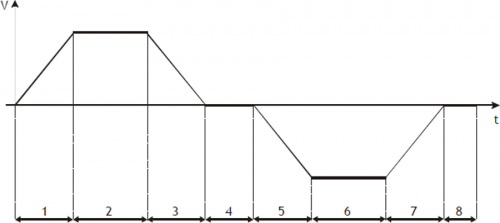
Settore 1 Acceleazione, con partenza da velocità zero e spostamento slave positivo (codeG = 131). È importante calcolare il rapporto dello spazio master/slave di questo tratto in modo che la velocità di uscita sia quella che poi verrà mantenuta dallasse slave nel tratto a velocità costante.
Settore 2 Intermedio con velocità costante e spostamento slave positivo (codeG = 133).
Settore 3 Decelerazione con velocità finale zero, con una possibile compensazione della velocità di frenata nella prima metà del tratto e spostamento slave positivo (codeG = 135). Potrebbe avere gli stessi valori impostati nel settore 1.
Settore 4 Fermata lavorazione con spostamento slave uguale a zero (codeG = 133). Si programma lo spazio master mentre quello slave viene impostato a 0.
Settore 5 Accelerazione, con partenza da velocità zero e spostamento slave negativo (codeG = 131). È importante calcolare il rapporto dello spazio master/slave di questo tratto in modo che la velocità di uscita sia quella che poi verrà mantenuta dallasse slave nel tratto a velocità costante. Teoricamente si possono impostare gli stessi valori inseriti nel settore 1 cambiando di segno la quota slave.
Settore 6 Intermedio con velocità costante e spostamento slave negativo (codeG = 133).
Settore 7 Decelerazione con velocità finale zero, con una possibile compensazione della velocità di frenata nella prima metà del tratto e spostamento slave negativo (codeG = 135). Potrebbe avere gli stessi valori impostati nel settore 5.
Settore 8 Fermata lavorazione con spostamento slave uguale a zero (codeG = 133). Si programma lo spazio master mentre quello slave viene impostato a 0.
Dopo avere eseguito il settore 8, ci dovranno essere delle funzioni che eseguono il rifasamento dei conteggi Master e Slave sottraendo lo spazio percorso fino a fine settore; successivamente si dovrà avere la riesecuzione automatica della stessa camma dal settore 1 (JUMP o loop camma).
0.3.15 Basi per la costruzione di una camma per taglio al volo con extravelocità
Come esempio consideriamo un semplice taglio al volo:
-
Partenza asse slave con rampa di accelerazione.
-
Raggiungimento della velocità master.
-
Mantenimento della velocità raggiunta per tutto il taglio.
-
Concluso il taglio lasse slave deve accelerare per portarsi ad una extravelocità, mantenendola per un certo spazio.
-
Stop asse slave con rampa di decelerazione.
-
Ritorno dellasse slave al punto di partenza (home), senza tempo di inversione ed eseguendo le rampe di accelerazione e decelerazione.
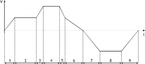
Settore 1 Accelerazione, con partenza da velocità zero e spostamento slave positivo (codeG = 132). Alla fine di questo settore lo slave avrà la stessa velocità del master.
Settore 2 Intermedio con velocità costante e spostamento slave positivo (codeG = 133). In questo settore lo spazio percorso dal master sarà uguale a quello percorso dallo slave.
Settore 3 Accelerazione e spostamento slave positivo (codeG = 133). Il codice impostato non è di accelerazione ma, per far accelerare lo slave rispetto al master, viene impostato uno spazio slave maggiore di quello master.
Settore 4 Intermedio con velocità costante e spostamento slave positivo (codeG = 133). In questo settore lo spazio percorso dallo slave sarà proporzione a quello percorso dal master.
Settore 5 Decelerazione e spostamento slave positivo (codeG = 133). In questo settore si porta lo slave alla stessa velocità del master.
Settore 6 Decelerazione con velocità finale zero, con una possibile compensazione della velocità di frenata nella prima metà del tratto e spostamento slave positivo (codeG = 135).
Settore 7 Accelerazione, con partenza da velocità zero e spostamento slave negativo (codeG = 131). In questo settore la velocità di uscita dello slave può essere diversa da quella del master.
Settore 8 Intermedio con velocità costante e spostamento slave negativo (codeG = 133).
Settore 9 Decelerazione con velocità finale zero, con una possibile compensazione della velocità di frenata nella prima metà del tratto e spostamento slave negativo (codeG = 135).
Dopo avere eseguito il settore 9, ci dovrà essere una funzione che esegua il rifasamento del conteggio del Master, sottraendo lo spazio percorso fino a fine settore e, successivamente, la riesecuzione automatica della stessa camma (JUMP o loop camma).
0.4 Gestione errori device
La presenza di un errore nel sistema camming viene segnalato dallo stato st_error.
Essendo causato da un evento grave e non essendo garantita in questa situazione la gestione
dellasse slave, si è deciso in modo arbitrario di bloccare lasse senza rampe come fosse avvenuta
unemergenza.
Quando st_error è uguale a 1, troviamo presente sulla variabile errcode il tipo di errore intervenuto
(vedi tabella) e nella variabile errvalue una indicazione sulla causa dellerrore
| Codice | Priorità | Descrizione |
|---|---|---|
| 1 | 0 | Troppi settori a campionamento nullo consecutivi |
| 2 | 0 | JUMP da un settore con velocità finale diversa da zero su un settore con velocità iniziale uguale a zero (codice di accelerazione). |
| 3 | 0 | Codice G del settore non valido. |
| 4 | 0 | Spazio master del settore camma troppo piccolo, quindi il settore non è calcolato. |
| 5 | 0 | Tentato di scrivere nel settore in esecuzione. |
| 6 | 0 | Nel codice di JUMP, è stato richiesto di andare ad una riga non compresa tra 1 e 128. |
| 7 | 0 | Settore con codeG = 160 non eseguito allinizio della camma. |
| 50 | 0 | Il valore del raggio introdotto è troppo piccolo per collegare il punto iniziale ed il punto finale della circonferenza. |
| 51 | 0 | Introdotti spostamenti nulli degli assi X ed Y ed un raggio diverso da 0: si è richiesto dunque di fare un arco di circonferenza nullo. |
Se il device va in errore, per poter riprendere la lavorazione bisogna cancellare lo stato st_error attraverso il comando RSERR e fare la consueta routine di ripristino da emergenza (RESUME asse).
NOTA: Lerrore 4 è dovuto al fatto che il settore viene eseguito in un tempo inferiore al tempo di campionamento del device, percui non può essere processato. Se ci si trova in questa situazione bisogna aumentare la quota del master nel settore oppure calare la velocità del master.
0.5 Gestione warning device
La presenza di un warning nel sistema camming viene segnalato dallo stato st_warning.
Essendo causato da un evento non grave ed essendo garantita in questa situazione la gestione
dellasse slave, lasse slave continua il suo lavoro.
Quando st_warning è uguale a 1, troviamo presente sulla variabile wrncode il tipo di warning
intervenuto (vedi tabella) e nella variabile wrnvalue il numero del settore della camma che ha
provocato il warning.
| Codice | Priorità | Descrizione |
|---|---|---|
| 1 | 6 | Costante di accelerazione settore maggiore di quella programmata. |
| 2 | 7 | Costante di decelerazione settore maggiore di quella programmata. |
| 3 | 4 | Saturazione dellanalogica slave a + 10V (con autoritenuta). |
| 4 | 5 | Saturazione dellanalogica slave a - 10V (con autoritenuta). |
| 5 | 9 | Velocità finale di segno opposto a quella iniziale. |
| 6 | 2 | Incontrato un settore di accelerazione quando la camma proviene da un settore con velocità finale diversa da zero. |
| 7 | 8 | Velocità intermedia di segno opposto a quella iniziale. |
| 8 | 0 | Evento catturato da ingresso in interrupt ma non elaborato immediatamente per sovraccarico nei calcoli del device. |
| 9 | 1 | Quota di partenza asse Slave con codeG = 160 già superata. |
| 10 | 10 | Sono stati incontrati due settori con codeG 154 e non é stato effettuato addolcimento rampa anche se abilitato. |
| 11 | 11 | Comando QCL non eseguito per condizioni non soddisfatte. |
| 12 | 3 | Asse fuori dalla soglia di sincronismo (variabile syncrange). |
La priorità più alta è contrassegnata da 0, la più bassa con 8.
Per cancellare lo stato st_warning bisogna inviare il comando RSWRN.
NOTA: In caso di warning 8, la funzione sará ritardata per un tempo sufficiente da consentire alla
CPU di terminare dei calcoli interni. Nel caso di start camma da ingresso di interruzione, la
posizione di avvio camma può non essere quella del momento dellinterrupt, ma quella dopo la
fine dei calcoli. Il tempo di esecuzione dei calcoli (espressi in tempo di campionamento del
device), è riportata nella tabella seguente:
| Parametri che comportano ricalcoli | N.ro campionamenti in cui sono distribuiti i conseguenti ricalcoli |
|---|---|
| codeG, codeQs, codeQm,codeQsa, codeQma, maxpos, minpos,prspos, prsposm,toll, tacc, tdec, taccmax, tdecmax, syncrange, pgain, feedfw, integt, derivt | 1 |
| tbfm | 2 |
| tbf | 3 |
| maxvel | 5 |
| decpt, unitvel | 6 |
| pulsem, measurem | 130 |
| pulse, measure | 139 |
0.6 Gestione master simulato
Lencoder master del device CAMMING4 non è in alcun modo legato allencoder del device EANPOS.
Il device CAMMING4 può gestire due tipi di master:
-
Entrambi possono essere provenienti da un encoder meccanicamente collegato al sistema
master ed elettricamente collegato al sistema QMOVE oppure encoder simulati. Viene inoltre
accettata la soluzione mista (uno collegato elettricamente ed uno simulato.)
Lo scambio tra i due encoder viene fatto attraverso il parametro mtype senza nessun vincolo, in
modo che, anche nellesecuzione di una camma, sia possibile fare lo scambio tra i dispositivi.
Nel sistema utilizzante il device CAMMING4 può essere dichiarato un encoder simulato utilizzando
un device di movimento (ad esempio un EANPOS) dichiarato con il contatore sullo slot 1
(normalmente riservato alla CPU del sistema) e tutte le altre periferiche disabilitate:
;--------------------------------
; Dichiarazione device interni
;--------------------------------

INTDEVICE
<nome_device>  EANPOS  TCamp  ICont    IntL  IAZero  IOutA
Master         EANPOS    2    1.CNT01  X     X.X     X.X
dove:
| <nome device> | Nome assegnato al device. |
| EANPOS | Parola chiave che identifica il device posizionatore analogico. |
| TCamp | Tempo di campionamento device (1÷255 ms). |
| ICont | Ingresso contatore bidirezionale. |
| IntL | Numero della linea di interrupt dedicata per limpulso di zero dellencoder durante la fase di ricerca di preset. |
| IAZero | Ingresso di labilitazione per lacquisizione dellimpulso di zero del trasduttore durante la fase di ricerca di preset. |
| IOutA | Indirizzo hardware del componente DAC delluscita analogica (obbligatoriamente dichiarata come X.X). |
Il device così configurato viene considerato come un master simulato e viene parametrizzato e utilizzato come fosse un device normale tenendo presente che il loop di regolazione deve essere aperto (st_loopon = 0) e di conseguenza non serve parametrizzare il P.I.D. ma è sufficiente impostare il feedforward al 100% (feedfw = 1000).
0.6.1 Esempio di programmazione
Si ipotizza di utilizzare il device EANPOS configurato come nellesempio precedente e di voler
dare il set di velocità (setvel) espresso in Hz. Si ipotizza inoltre che il master simulato debba
continuare il suo movimento allinfinito.
Il flag sf01 esegue lo start e lo stop del device simulato.
;----------------------------------------------------
; Gestione del master simulato
;----------------------------------------------------

Master:measure = 1000
Master:pulse = 4000
Master:decpt = 0
Master:unitvel = 1
Master:maxvel = 1000
Master:taccdec = 100
Master:maxpos = 999999
Master:minpos = -999999
INIT Master
WAIT Master:st_init
LOOPOFF Master
WAIT NOT Master:st_loopon
RESUME Master
WAIT NOT Master:st_emrg

MAIN:
IF sf01
  IF Master: st_still
    Master:posit = 0
    Master:setvel = 500
    Master:setpos = 999999
    START Master
  ENDIF
  IF Master:posit GE 500000
    Master:posit = 0
  ENDIF
ELSE
  IF NOT Master:st_still
    STOP Master
  ENDIF
ENDIF

WAIT 1
JUMP MAIN
END
0.7 Limitazione rapporto frequenze trasduttore M/S
Per avere un corretto funzionamento durante la fase di sincronismo, si richiede che gli impulsi nel tempo (frequenza) generati dal trasduttore Master siano maggiori o uguali a quelli dellasse Slave. In ogni caso si richiede di rispettare la condizione
Frequenza slave = 1,5 × Frequenza master
Nel caso di un non rispetto di questa condizione si hanno dei problemi nella taratura dellasse Slave in sincronismo a causa di una rugosità nel movimento.
0.8 Tabella di configurazione ingressi
Il device ha la possibilità di gestire un ingresso normale ed un ingresso in interrupt per eseguire comandi o eseguire azioni. Lindirizzo degli ingressi è configurabile nel file di configurazione (InG ed InGInt). Per far eseguire una funzione specifica allingresso, è sufficiente assegnare alla variabile funInp (se si tratta di ingresso normale) oppure funInt (se si tratta di ingresso in interrupt) il codice riportato nella tabella seguente.
| Codice | Funzione ingresso |
|---|---|
| 00 | Ingresso disabilitato |
| 01 | STOPCAM |
| 02 | STARTCAM |
| 03 | Scrive il valore della variabile encoder nella variabile delta1 |
| 04 | Scrive il valore della variabile encoderm nella variabile delta2 |
| 05 | Incrementa di 1 la variabile delta1 |
| 06 | Incrementa di 1 la variabile delta2 |
| 07 | Scrive il contenuto della variabile delta1 in encoder |
| 08 | Scrive il contenuto della variabile delta2 in encoderm |
| 09 | Scrive il valore della variabile encoder nella variabile delta1 + STARTCAM |
| 10 | Scrive il valore della variabile encoderm nella variabile delta2 + STARTCAM |
| 11 | Scrive il valore della variabile encoder nella variabile delta1 + STARTCAM; viene bloccato il comando di STOPCAM per un tempo di 25 mSec. |
| 12 | Scrive il valore della variabile encoderm nella variabile delta2 + STARTCAM; viene bloccato il comando di STOPCAM per un tempo di 25 mSec. |
Tutte le funzioni degli ingressi possono essere gestiti sia su ingressi normali che su ingressi in
interrupt.
Per avere un corretto funzionamento degli ingressi, bisogna che essi siano attivati rispettando le
condizioni richieste nella descrizione del comando o dellazione descritta.
0.9 Tabella di configurazione uscite
Il device ha la possibilità di gestire un uscita per segnalare alcuni stati. Lindirizzo delluscita è configurabile nel file di configurazione (Out). Per far eseguire una funzione specifica alluscita, è sufficiente assegnare alla variabile funOut il codice riportato nella tabella seguente.
| Codice | Funzione uscita |
|---|---|
| 00 | Uscita disabilitata |
| 01 | Disattivazione uscita |
| 02 | Attivazione uscita |
| 03 | st_toll |
| 04 | st_tpos |
| 05 | st_sync |
| 06 | Si attiva luscita solamente se codeMex é uguale al valore 1000 |
| 07 | Si attiva luscita solamente se codeMex é uguale al valore 1000 e st_sync é attivo |
| 08 | Si attiva luscita solamente se codeMex é uguale al valore 1001 |
| 09 | Si attiva luscita solamente se codeMex é uguale al valore 1002 |
0.10 Tabella comandi, stati e parametri: Simbologia adottata
Il nome del parametro, stato o comando viene riportato alla sinistra della tabella.
=R\\=
Indica se il relativo parametro o stato è ritentivo (al momento dellinizializzazione del device
mantiene lo stato precedentemente definito), oppure lo stato che assume al momento
dellinizializzazione del device.
R = Ritentivo
0 = Al momento dellinizializzazione del device il valore viene forzato a zero.
1 = Al momento dellinizializzazione del device il valore viene forzato a uno.
=D\\=
Indica la dimensione del parametro.
F = Flag
B = Byte
W = Word
L = Long
0.10.1 Condizioni
Vengono descritte tutte le condizioni necessarie affinché il parametro sia considerato corretto o
perché il comando venga accettato.
In alcuni casi vengono specificati dei valori limite per laccettazione del parametro: se vengono
introdotti dei valori esterni ai limiti impostati, il dato viene comunque accettato; pertanto
devono essere previsti opportuni controlli interni tali da garantire il corretto funzionamento.
Per lesecuzione di un comando, tutte le relative condizioni devono necessariamente essere
soddisfatte; in caso contrario il comando non viene eseguito.
A
Indica la modalità di accesso.
R = Read (lettura).
W = Write (scrittura).
0.10.2 PARAMETRI
| Nome | D | Condiz. scritt. | R | A | Descrizione |
|---|---|---|---|---|---|
| decpt | B | st_still = 1 st_camex = 0 st_prson = 0 | R | RdWr | Decimal point (0÷3) Definisce la precisione con la quale si intendono impostare le preselezioni e visualizzare i conteggi relativamente allasse slave. |
| measure | L | st_still = 1 st_camex = 0 st_prson = 0 | R | RdWr | Measure (1÷999999) Indica lo spazio, in unità di misura, percorso dallasse slave per ottenere gli impulsi encoder impostati nel parametro pulse. Questo parametro è utilizzato per il calcolo della risoluzione dellasse con la formula: Risoluzione = measure* 4 / pulse La risoluzione deve avere un valore compreso tra 0.00374 e 4.00000. |
| pulse | L | st_still = 1 st_camex = 0 st_prson = 0 | R | RdWr | Pulse encoder (1÷999999) Indica gli impulsi moltiplicato 4 forniti dallencoder slave per ottenere lo spazio impostato nel parametro measure. Questo parametro è utilizzato per il calcolo della risoluzione dellasse con la formula: Risoluzione = measure* 4 / pulse La risoluzione deve avere un valore compreso tra 0.00374 e 4.00000. |
| measurem | L | st_still = 1 st_camex = 0 st_prson = 0 | R | RdWr | Measure of master (1÷999999) Indica lo spazio, in unità di misura, percorso dallasse master per ottenere gli impulsi encoder impostati nel parametro pulsem. Questo parametro è utilizzato per il calcolo della risoluzione dellasse con la formula: Risoluzione = measurem * 4 / pulsem La risoluzione deve avere un valore compreso tra 0.00374 e 4.00000. |
| pulsem | L | st_still = 1 st_camex = 0 st_prson = 0 | R | RdWr | Pulse encoder of master (1÷999999) Indica gli impulsi moltiplicato 4 forniti dallencoder master per ottenere lo spazio impostato nel parametro measurem. Questo parametro è utilizzato per il calcolo della risoluzione dellasse con la formula: Risoluzione = measurem* 4 / pulsem La risoluzione deve avere un valore compreso tra 0.00374 e 4.00000. |
| unitvel | B | st_still = 1 st_camex = 0 st_prson = 0 | R | RdWr | Velocity unit (0÷1) Definisce se lunità di tempo della velocità dello slave è espressa in minuti o secondi. 0 = Um/min, 1 = Um/sec. |
| maxvel | L | st_still = 1 st_camex = 0 st_prson = 0 | R | RdWr | Max velocity (0÷999999) Definisce la massima velocità dellasse slave (relativa al riferimento analogico di +/-10V). Il valore introdotto è nellunità di tempo della velocità impostata nel parametro unitvel. |
| prsvel | L | st_prson = 0 | R | RdWr | Preset velocity (0÷maxvel) Definisce la velocità dellasse slave durante la procedura di ricerca di preset. Il valore introdotto è nellunità di tempo della velocità impostata nel parametro unitvel. |
| sprsvel | L | st_prson = 0 | R | RdWr | Preset velocity (0÷maxvel) Definisce la velocità dellasse slave durante la procedura di ricerca di preset. Il valore introdotto è nellunità di tempo della velocità impostata nel parametro unitvel. |
| taccmax | W | st_prson = 0 | R | RdWr | Search preset velocity (0÷prsvel) Nella procedura di ricerca di preset dello slave, definisce la velocità dellasse nella fase di acquisizione dellimpulso di zero. Il valore introdotto è nellunità di tempo della velocità impostata nel parametro unitvel. |
| tdecmax | W | st_prson = 0 | R | RdWr | Max deceleration time (0÷999) Usato durante lesecuzione della camma per eseguire le comparazioni sul gradiente di decelerazione massimo. Definisce il tempo minimo di decelerazione con cui lasse slave può portarsi da velocità massima ad asse fermo (velocità uguale a zero). Il valore introdotto è espresso in centesimi di secondo. |
| tacc | W | - | R | RdWr | Acceleration time (0÷999) Definisce il tempo impiegato dallasse slave per portarsi da fermo alla velocità massima. Il valore introdotto è espresso in centesimi di secondo. Se lasse si sta muovendo (st_still = 0) si possono cambiare i gradienti della rampa solamente se i nuovi valori consentono di raggiungere la quota impostata. |
| tdec | W | - | R | RdWr | Deceleration time (0÷999) Definisce il tempo necessario allasse slave per decelerare dalla velocità massima a zero (condizione di asse fermo). Il valore introdotto è espresso in centesimi di secondo. Se lasse si sta muovendo (st_still = 0) si possono cambiare i gradienti della rampa solamente se i nuovi valori consentono di raggiungere la quota impostata. |
| maxpos | L | st_still = 0 | R | RdWr | Max position (-999999÷999999) Definisce la massima quota raggiungibile dallasse slave. Tale limite non è controllato durante lesecuzione della camma. |
| minpos | L | st_still = 0 | R | RdWr | Min position (-999999÷999999) Definisce la minima quota raggiungibile dallasse slave. Tale limite non è controllato durante lesecuzione della camma. |
| prspos | L | st_still = 0 | R | RdWr | Preset position (minpos÷maxpos) Definisce il valore che viene caricato sul conteggio slave con la procedura di ricerca di preset. |
| prsposm | L | st_prsonm = 0 | R | RdWr | Preset position of master (-999999 ÷999999) Definisce il valore che viene caricato sul conteggio master con la procedura di ricerca di preset. |
| toll | L | st_still = 0 | R | RdWr | Tolerance (0÷999999) Definisce una fascia di conteggio intorno alle quote di posizionamento dellasse slave. Se il posizionamento (non larrivo in camma) si conclude entro tale fascia, è da considerarsi corretto e viene segnalato attraverso lo stato st_toll. |
| maxfollerr | L | - | R | RdWr | Maximum following error (0÷2 31-1) Definisce il massimo scostamento accettabile tra la posizione teorica e la posizione reale dellasse slave. Il valore introdotto è espresso in bit trasduttore per 4. |
| syncrange | L | - | R | RdWr | Synchronism range (0÷999999) È il valore espresso in unità di misura entro il quale viene segnalato il sincronismo slave (st_sync = 1) rispetto al master durante lesecuzione della camma. |
| prsmode | B | st_prson = 0 | R | RdWr | Preset mode (0÷2) Definisce il tipo di ricerca di preset dello slave: 0 = Per la ricerca dellabilitazione impulso di zero, lasse inizia il movimento in veloce, incontra il segnale di abilitazione, inverte la direzione rallentando e, sul fronte di discesa relativo al segnale di abilitazione dellasse slave, carica la quota di preset. 1 = Per la ricerca dellabilitazione impulso di zero, lasse inizia il movimento in veloce, incontra il segnale di abilitazione, inverte la direzione ed in lento acquisisce il primo impulso di zero (dopo la disattivazione del segnale di abilitazione dellasse slave). 2 =Non viene attivata la procedura di ricerca preset (st_prson = 0). Il conteggio viene aggiornato alla quota di preset allattivazione dellabilitazione impulso di zero dellasse slave. |
| prsmodem | B | st_prsonm = 0 | R | RdWr | Preset mode of master (0÷2) Definisce il tipo di ricerca di preset del master: 0 = Se st_prsonm = 1, il conteggio viene aggiornato alla quota di preset alla disattivazione dellabilitazione impulso di zero dellasse master. 1 = Se st_prsonm = 1, il conteggio viene aggiornato alla quota di preset allattivazione dellimpulso di zero dopo la disattivazione dellabilitazione impulso di zero dellasse master. 2 =Non viene attivata la procedura di ricerca preset (st_prsonm = 0). Il conteggio viene aggiornato alla quota di preset allattivazione dellabilitazione impulso di zero dellasse master. |
| prsdir | B | st_prson = 0 | R | RdWr | Preset search direction (0÷1) Definisce la direzione del movimento asse per la ricerca del finecorsa di abilitazione impulso di zero dellasse slave. 0 = lasse si dirige in avanti. 1 = lasse si dirige indietro. |
| mtype | B | - | R | RdWr | Master type (0÷1) Definisce lindirizzo del master utilizzato: 0 = Il master è lencoder avente indirizzo “A”. 1 = Il master è lencoder avente indirizzo “B”. (Vedi capitolo “Gestione master simulato”) |
| ramptype | B | st_still = 0 | R | RdWr | Ramp type of slave (0÷1) Definisce il tipo di rampe dello slave utilizzate nei normali posizionamenti; nellesecuzione della camma i raccordi saranno sempre eseguiti con rampe trapezoidali: 0 = rampe trapezoidali. 1 = rampe epicicloidali. (Vedi capitolo “Descrizione movimento trapezoidale”) |
| rtype | B | - | R | RdWr | Riduction profile type (0÷1) Definisce il tipo di riduzione del profilo di posizionamento dellasse slave se sono state selezionate le rampe di tipo epicicloidale (ramptype = 1). 0 = I tempi di accelerazione e di decelerazione rimangono quelli della velocità impostata e viene diminuita proporzionalmente la velocità, 1 = Vengono diminuiti i tempi di accelerazione e di decelerazione (mantenendo il gradiente di accelerazione e di decelerazione impostato) e anche la velocità stessa. (Vedi capitolo “Descrizione movimento trapezoidale”) |
| stopt | B | - | R | RdWr | Stop type (0÷1) Definisce il tipo di frenata che viene utilizzata in caso di stop posizionamento dellasse slave se sono state selezionate le rampe di tipo epicicloidale (ramptype = 1). 0 = Quando si esegue una frenata in rampa viene prima completata le rampa di accelerazione e poi viene eseguita la rampa di decelerazione, 1 = Quando viene eseguita una frenata in rampa viene immediatamente eseguita la rampa di decelerazione. (Vedi capitolo “Descrizione movimento trapezoidale”) |
| pgain | W | - | R | RdWr | Proportional gain (0÷32767) Impostando il valore 1000, il coefficente è 1.000. È il coefficente che moltiplicato per lerrore di inseguimento genera la parte proporzionale delluscita di regolazione dellasse slave. (Vedi capitolo dedicato) |
| feedfw | W | - | R | RdWr | Feed forward (0÷32767) Impostando il valore 1000, la percentuale è del 100%. È il coefficente percentuale che, moltiplicato per la velocità istantanea, genera la parte feed-forward delluscita di regolazione dellasse slave. (Vedi capitolo dedicato). |
| integt | W | - | R | RdWr | Integral time (0÷32767) È il tempo, espresso in millisecondi, che produce il coefficente di integrazione dellerrore di inseguimento. Lintegrazione di tale errore moltiplicata per tale coefficente genera la parte integrale delluscita di regolazione dellasse slave. (Vedi capitolo dedicato) |
| derivt | W | - | R | RdWr | Derivation time (0÷32767) È il tempo, espresso in millisecondi, che produce il coefficente derivativo dellerrore di inseguimento. La derivazione di tale errore moltiplicata per tale coefficente genera la parte integrale delluscita di regolazione dellasse slave. ( Vedi capitolo dedicato) |
| offset | W | - | R | RdWr | Offset output (-32767÷32767) Offset uscita DAC asse slave espressa in bit. Definisce il valore in bit della correzione relativa alluscita analogica dellasse slave in modo da compensare leventuale deriva del sistema. |
| tbfm | W | - | R | RdWr | Time base frequency-meter master (0÷3) Definisce il tempo di campionamento del frequenzimetro relativo allasse master. 0 = 240 ms, 1 = 480 ms, 2 = 24 ms, 3 = 120 ms. N.B. Minore è il tempo di campionamento, più veloce è lacquisizione della frequenza, ma maggiore è lerrore alle basse frequenze. |
| tbf | W | - | R | RdWr | Time base frequency-meter slave (0÷3) Definisce il tempo di campionamento del frequenzimetro relativo allasse slave. 0 = 240 ms, 1 = 480 ms, 2 = 24 ms, 3 = 120 ms. N.B. Minore è il tempo di campionamento, più veloce è lacquisizione della frequenza, ma maggiore è lerrore alle basse frequenze. |
0.10.3 VARIABILI ASSE
| Nome | D | Condiz. scritt. | R | A | Descrizione |
|---|---|---|---|---|---|
| frqm | L | - | 0 | RdWr | Actual frequency of master Indica la frequenza del trasduttore relativo allasse master. Per modificare la precisione riferirsi al parametro tbfm. Il valore è espresso in Hz |
| positm | L | st_init = 1 st_camex = 0 | R | RdWr | Actual position of master (-999999 ÷ +999999) Indica la posizione attuale dellasse master. Il valore è espresso in unità di misura. |
| encoderm | L | st_init = 1 st_camex = 0 | R | RdWr | Encoder value of master Indica la posizione attuale dellasse master. Il valore è espresso in bit encoder per 4. |
| vout | B | st_init = 1 st_cal = 1 | 0 | RdWr | Output voltage (-100÷100) Impostando il valore 100, la percentuale è del 100%. Consente limpostazione o la visualizzazione (in questo caso senza nessuna condizione) della tensione di uscita relativa alluscita analogica dellasse slave. Il dato è espresso in decimi di Volt. |
| follerr | L | - | 0 | Rd | Following error Indica lerrore tra la posizione teorica e la posizione reale dellasse slave in valore assoluto. Il valore è espresso in bit trasduttore per 4. |
| vel | L | - | 0 | Rd | Actual velocity Indica la velocità attuale dellasse slave. Il valore letto è espresso nellunità di tempo della velocità impostata (Velocity unit). |
| frq | L | - | 0 | Rd | Actual frequency Indica la frequenza del trasduttore relativo allasse slave. Il valore letto è espresso in Hz |
| posit | L | st_init = 1 st_camex = 0 | R | RdWr | Actual position (-999999 ÷ +999999) Indica la posizione attuale dellasse slave. Il valore introdotto o letto è espresso in unità di misura. |
| encoder | L | st_init = 1 st_camex = 0 | R | RdWr | Encoder value (-2 31÷2 31-1) Indica la posizione attuale dellasse slave. Il valore letto è espresso in bit trasduttore per 4. |
| delta1 | L | - | R | RdWr | Delta 1 (-2 31÷2 31-1) Variabile duso generico. Utilizzata come registro per scambio dati. |
| delta2 | L | - | R | RdWr | Delta 2 (-2 31÷2 31-1) Variabile duso generico. Utilizzata come registro per scambio dati. |
| setvel | L | - | R | RdWr | Set velocity (0÷maxvel) Definisce la velocità dellasse slave nei posizionamenti. Il valore introdotto è nellunità di tempo della velocità impostata (Velocity unit). Se lasse si sta muovendo (st_still = 0) si può cambiare il setpoint di velocità solamente se il nuovo valore consente di raggiungere la quota impostata. |
| setpos | L | - | R | RdWr | Set position (minpos÷maxpos) Definisce la quota di posizionamento raggiungibile dallasse slave alla velocità setvel. |
| rowex | W | - | 0 | Rd | Row in use (0÷40) Definisce il numero del settore in secuzione. |
| ffwdreg | L | - | 0 | Rd | Feed-forward register (-2 31÷2 31-1) È il valore istantaneo del registro di feed-forward espresso in bit. |
| propreg | L | - | 0 | Rd | Proportional register (-2 31÷2 31-1) È il valore istantaneo del registro di proporzionale espresso in bit. |
| intreg | L | - | 0 | Rd | Integral register (-2 31÷2 31-1) Registro integrale asse slave. |
| derreg | L | - | 0 | Rd | Derivate register (-2 31÷2 31-1) Registro derivata asse slave. |
| codeMex | L | - | 0 | Rd | Code M in execution (-2 31÷2 31-1) Consente la lettura del codice M del settore in esecuzione. |
| funInp | B | - | R | RdWr | Programmable function of input (0÷99) Consente di configurare il funzionamento dellingresso normale come da tabella configurazione ingressi. (Vedi capitolo dedicato) |
| funInt | B | - | R | RdWr | Programmable function of interrupt input (0÷99) Consente di configurare il funzionamento dellingresso in interrupt come da tabella configurazione ingressi. (Vedi capitolo dedicato) |
| funOut | B | - | R | RdWr | Programmable function of output (0÷99) Consente di configurare il funzionamento delluscita come da tabella configurazione uscite. (Vedi capitolo dedicato) |
| inpcapt | B | - | 0 | RdWr | Capture mode (0÷2) Definisce il modo di cattura della funzione dellingresso per funzione generica (vedi file di configurazione). 0 = Disabilitato. 1 = Singola cattura sul fronte di discesa. 2 = Singola cattura sul fronte di salita. La cattura è abilitata se lo stato st_enbl = 1. |
| intcapt | B | - | 0 | RdWr | Interrupt capture mode (0÷2) Definisce il modo di cattura della funzione dellingresso in interrupt (vedi file di configurazione). 0 = Disabilitato. 1 = Singola cattura sul fronte di discesa. 2 = Singola cattura sul fronte di salita. La cattura è abilitata se lo stato vt_intenbl = 1. |
| errcode | B | - | 0 | Rd | Error code (0÷100) Indica il tipo di errore intervenuto nel sistema. Il codice è valido solo se st_error = 1. (Vedi capitolo dedicato) |
| errvalue | B | - | 0 | Rd | Error value (0÷100) Specifica il settore che ha causato lerrore nel sistema. Il valore è valido solo se st_error = 1. (Vedi capitolo dedicato) |
| wrncode | B | - | 0 | Rd | Warning code (0÷100) Indica il tipo di warning intervenuto nel sistema. Il codice è valido solo se st_warning = 1. (Vedi capitolo dedicato) |
| wrnvalue | B | - | 0 | Rd | Warning value (0÷100) Specifica il settore che ha causato il warning nel sistema. Il valore è valido solo se st_warning = 1. (Vedi capitolo dedicato) |
0.10.4 VARIABILI DI PROGRAMMA
| Nome | D | Condiz. scritt. | R | A | Descrizione |
|---|---|---|---|---|---|
| codeG1 | W | rowex ?1 | R | RdWr | Code G1 Indica il valore che assume il codice G nel passo 1. Vedi descrizione codici G. |
| codeG2 | W | rowex ?2 | R | RdWr | Code G2 Indica il valore che assume il codice G nel passo 2. Vedi descrizione codici G. |
| codeG128 | W | rowex ?128 | R | RdWr | Code G128 Indica il valore che assume il codice G nel passo 128. Vedi descrizione codici G. |
| codeQm1 | L | rowex ?1 | R | RdWr | Code Q1 master (0÷999999) Indica la quota incrementale master del settore 1. Il valore introdotto è in unità di misura. |
| codeQm2 | L | rowex ?2 | R | RdWr | Code Q2 master (0÷999999) Indica la quota incrementale master del settore 2. Il valore introdotto è in unità di misura. |
| codeQm128 | L | rowex ?128 | R | RdWr | Code Q128 master (0÷999999) Indica la quota incrementale master del settore 128. Il valore introdotto è in unità di misura. |
| codeQs1 | L | rowex ?1 | R | RdWr | Code Q1 slave (-999999÷999999) Indica la quota incrementale slave del settore 1. Il valore introdotto è in unità di misura. |
| codeQs2 | L | rowex ?2 | R | RdWr | Code Q2 slave (-999999÷999999) Indica la quota incrementale slave del settore 2. Il valore introdotto è in unità di misura. |
| codeQs128 | L | rowex ?128 | R | RdWr | Code Q128 slave (-999999÷999999) Indica la quota incrementale slave del settore 128. Il valore introdotto è in unità di misura. |
| codeQma1 | L | rowex ?1 | R | RdWr | Code Q1 auxiliary master (0÷999999) Indica la quota ausiliaria incrementale master del settore 1. Il valore introdotto è in unità di misura. |
| codeQma2 | L | rowex ?2 | R | RdWr | Code Q2 auxiliary master (0÷999999) Indica la quota ausiliaria incrementale master del settore. Il valore introdotto è in unità di misura. |
| codeQma128 | L | rowex ?128 | R | RdWr | Code Q128 master (-999999÷999999) Indica la quota incrementale master del settore 128. Il valore introdotto è in unità di misura. |
| codeQsa1 | L | rowex ?1 | R | RdWr | Code Q1 auxiliary slave (-999999÷999999) Indica la quota ausiliaria incrementale slave del settore 1. Il valore introdotto è in unità di misura. |
| codeQsa2 | L | rowex ?2 | R | RdWr | Code Q2 auxiliary slave (-999999÷999999) Indica la quota ausiliaria incrementale slave del settore 2. Il valore introdotto è in unità di misura. |
| codeQsa128 | L | rowex ?128 | R | RdWr | Code Q128 auxiliary slave (-999999÷999999) Indica la quota ausiliaria incrementale slave del settore 128. Il valore introdotto è in unità di misura. |
| codeM1 | L | rowex ?1 | R | RdWr | Code M1 Introduce un codice non inerente al posizionamento, ma che identifica una variabile che potrà essere poi elaborata dal programma applicativo (codice utensile, tipo lavorazione, numero pezzi …). |
| codeM2 | L | rowex ?2 | R | RdWr | Code M2 Introduce un codice non inerente al posizionamento, ma che identifica una variabile che potrà essere poi elaborata dal programma applicativo (codice utensile, tipo lavorazione, numero pezzi …). |
| codeM128 | L | rowex ?128 | R | RdWr | Code M128 Introduce un codice non inerente al posizionamento, ma che identifica una variabile che potrà essere poi elaborata dal programma applicativo (codice utensile, tipo lavorazione, numero pezzi …). |
0.10.5 COMANDI
| Nome | Condizioni | Descrizione |
|---|---|---|
| INIT | st_init = 0 | Init\ Comando di inizializzazione device. Se il device non é inizializzato non vengono eseguiti i calcoli relativi allasse e quindi rimane inattivo. Con comando INIT lasse verrà inizializzato, eseguendo i calcoli una sola volta. Attiva lo stato st_init. |
| EMRG | st_init = 1 | Emergency Pone in emergenza lasse slave interrompendo, senza rampa di decelerazione, leventuale movimento in corso. Viene inoltre disabilitata la reazione di spazio dellasse. |
| RESUME | st_init = 1 st_emrg = 1 | Resume Ripristino della condizione di emergenza dellasse slave; viene riabilitata la reazione di spazio. Allacquisizione dello start, lasse riprende il posizionamento. |
| STOP | st_init = 1 st_regoff = 0 st_emrg = 0 st_cal = 0 st_still = 0 st_camex = 0 | Stop Interrompe leventuale posizionamento in corso dellasse slave. La fermata dellasse avviene seguendo la rampa di decelerazione impostata nel parametro tdec. Lasse rimane in reazione di spazio. |
| START | st_init = 1 st_regoff = 0 st_emrg = 0 st_cal = 0 st_still = 0 st_camex = 0 st_prson = 0 | Start Lasse slave inizia il posizionamento alla quota setpos con velocitá impostata in setvel. |
| PRESET | st_init = 1 st_regoff = 0 st_emrg = 0 st_cal = 0 st_still = 0 st_camex = 0 | Preset Start ricerca preset asse slave. Viene dato inizio alla procedura di ricerca di preset con le modalità impostate con i parametri prsmode e prsdir. Se la ricerca di preset è già in esecuzione, il comando esegue linversione del senso di ricerca. |
| RSPRSOK | st_init = 1 st_prson = 0 | Reset stato st_prsok Azzera lo stato st_prsok |
| PRESETM | st_init = 1 st_camex = 0 st_prson = 0 | Master preset Start ricerca preset asse master. Viene dato inizio alla procedura di ricerca di preset con le modalità impostate con il parametro prsmodem. |
| RSPRSM | st_init = 0 st_prson = 0 | Reset preset of master Azzera lo stato st_prsokm se il preset del master è concluso. Se il preset del master è in corso (st_prsonm = 1) viene bloccato |
| RSERR | st_init = 1 | Reset status st_error Azzera lo stato st_error ed il relativo codice di errore errcode ed errvalue. |
| RSWRN | st_init = 1 | Reset status st_warning Azzera lo stato st_warning ed il relativo codice di warning wrncode ed wrnvalue. |
| LOOPON | st_init = 1 st_loopon = 1 | Loop on Abilita la reazione di spazio dellasse slave. Luscita analogica contrasta ogni azione esterna che tenti di spostare lasse dalla posizione raggiunta (deriva, operatore, …). Questa operazione azzera leventuale errore di inseguimento follerr. |
| LOOPOFF | st_init = 1 st_loopon = 1 | Loop off Disabilita la reazione di spazio dellasse slave. Lasse può essere spostato dalla sua posizione senza che luscita analogica contrasti il movimento. |
| MANFW | st_init = 1 st_regoff = 0 st_prson = 0 st_camex = 0 st_cal = 0 st_still = 1 st_emrg = 0 | Forward Movimento manuale asse slave in avanti. Comanda il movimento manuale in avanti dellasse alla velocità impostata con setvel. Il movimento viene fermato con il comando di STOP. |
| MANBW | st_init = 1 st_regoff = 0 st_prson = 0 st_camex = 0 st_cal = 0 st_still = 1 st_emrg = 0 | Backward Movimento manuale asse slave in indietro. Comanda il movimento manuale indietro dellasse alla velocità impostata con setvel. Il movimento viene interrotto con il comando di STOP. |
| CALON | st_init = 1 | Volt generator on Luscita analogica dellasse slave viene impiegata come generatore di tensione; in questo caso non è possibile usarla per posizionare lasse. Il valore in uscita è settabile a piacere tramite la variabile vout. |
| CALOFF | st_init = 1 st_cal = 0 | Volt generator off Luscita analogica dellasse slave non viene gestita come generatore di tensione, pertanto può essere nuovamente usata per la gestione dei posizionamenti. |
| CNTLOCK | st_init = 1 | Lock counter Blocca lacquisizione del conteggio dellasse slave anche se il trasduttore continua ad inviare i segnali. In questa fase leventuale spostamento dellasse non viene rilevato. |
| CNTUNLOCK | st_init = 1 | Unlock counter Sblocca il conteggio dellasse slave. Viene ripresa la lettura dei segnali inviati dal trasduttore e, di conseguenza, laggiornamento del conteggio. |
| CNTREV | st_init = 1 | Reverse counter Consente di invertire le fasi del trasduttore slave allinterno del device. Viene quindi invertito il senso del conteggio (Incremento/decremento). |
| CNTDIR | st_init = 1 | Direct counter Ripristina la direzione del conteggio del trasduttore dellasse slave. |
| CNTLOCKM | st_init = 1 | Lock counter master Blocca lacquisizione del conteggio asse master anche se il trasduttore continua ad inviare i segnali. In questa fase leventuale spostamento dellasse non viene rilevato. |
| CNTUNLOCKM | st_init = 1 | Unlock counter master Sblocca il conteggio dellasse master. Viene ripresa la lettura dei segnali inviati dal trasduttore e, di conseguenza, laggiornamento del conteggio. |
| CNTREVM | st_init = 1 | Reverse counter master Consente di invertire le fasi del trasduttore master allinterno del device. Viene quindi invertito il senso del conteggio (Incremento/decremento). |
| CNTDIRM | st_init = 1 | Direct counter master Ripristina la direzione del conteggio del trasduttore dellasse master. |
| STOPCAM | st_init = 1 st_camex = 1 | Stop cam Interrompe la camma in corso. La fermata dellasse avviene seguendo una rampa di decelerazione asincrona, secondo il parametro tdec. Lasse rimane in reazione di spazio. |
| STARTCAM | st_init = 1 st_still = 1 st_camex = 1 st_prson = 0 st_emrg = 0 st_regoff = 0 | Start cam Lasse inizia il posizionamento dellasse slave partendo con lelaborazione del settore 1 della camma introdotta ed eseguendo il codice descritto. |
| REGOFF | st_init = 1 st_still = 1 st_camex = 0 t_prson = 0 | Regulation OFF Disabilita la regolazione e laggiornamento del DAC dellasse slave, nonché tutti i comandi di movimento. |
| REGON | st_init = 1 st_still = 1 st_regoff = 1 st_emrg = 0 | Regulation ON Riabilita la regolazione e laggiornamento del DAC dellasse slave, nonché tutti i comandi di movimento. |
| ENBL | st_init = 1 | Reverse counter Consente di invertire le fasi del trasduttore slave allinterno del device. Viene quindi invertito il senso del conteggio (Incremento/ decremento). |
| INTENBL | st_init = 1 | Direct counter Ripristina la direzione del conteggio del trasduttore dellasse slave. |
| DSBL | st_init = 1 | Lock counter master Blocca lacquisizione del conteggio asse master anche se il trasduttore continua ad inviare i segnali. In questa fase leventuale spostamento dellasse non viene rilevato. |
| INTDSBL | st_init = 1 intcapt > 0 | Interrupt disable Disabilita la funzione dellingresso in interrupt inserita nel parametro funInt. Disattiva lo stato st_intenbl. |
| RSCAPT | st_init = 1 st_capt = 1 | Reset status of capture input Disattiva lo stato di st_capt. |
| RSINTCAPT | st_init = 1 st_intcapt = 1 | Reset status of capture interrupt input Disattiva lo stato di st_intcapt. |
| DELCNT | st_init = 1 st_still = 1 t_camex = 0 st_prson = 0 st_cal = 0 st_regoff = 0 | Delta counter Il conteggio dellasse slave (posizione dellasse) viene modificato sommandogli algebricamente il valore specificato nel parametro delta1 (posit = posit + delta1). |
| DELCNTM | st_init = 1 st_prsonm = 0 st_camex = 0 | Delta counter of master Il conteggio dellasse master (posizione dellasse) viene modificato sommandogli algebricamente il valore specificato nel parametro delta2 (positm = positm + delta2). |
0.10.6 STATI
| Nome | Dim. | Condiz. scritt. | Accesso | Descrizione |
|---|---|---|---|---|
| st_init | F | - | Rd | Init Segnalazione di device inizializzato. 0 = device non inizializzato 1 = device inizializzato Allaccensione per default viene caricato il valore zero. |
| st_chvel | F | - | Rd | Status of enable velocity change Segnala che il device può accettare un setpoint di velocità dellasse slave diverso da quello in esecuzione e porlo in esecuzione eseguendo la procedura di cambio velocità. La procedura di cambio velocità è disponibile solamente durante i posizionamenti (non durante lesecuzione della camma). Allaccensione per default viene caricato il valore zero. |
| st_emrg | F | - | Rd | Emergency (0÷1) Segnalazione di asse slave in emergenza. 0 = asse non in emergenza 1 = asse in emergenza Allaccensione per default viene caricato il valore zero. |
| st_toll | F | - | Rd | Tolerance (0÷1) Segnalazione di asse slave in tolleranza rispetto alla quota posta in esecuzione dal comando di START. 0 = asse non in tolleranza 1 = asse in tolleranza Allaccensione per default viene caricato il valore zero. |
| st_tpos | F | - | Rd | Tolerance of set position (0÷1) Indica che il conteggio dellasse slave è allinterno della fascia di tolleranza rispetto alla quota presente nella variabile setpos indipendentemente dal fatto che sia stato dato uno START o no. 0 = asse non in tolleranza 1 = asse in tolleranza Allaccensione per default viene caricato il valore zero. |
| st_prson | F | - | Rd | Preset ON (0÷1) Segnalazione di ricerca di preset asse slave conclusa correttamente 0 = ricerca di preset non ancora conclusa o non eseguita 1 = ricerca di preset conclusa correttamente All'accensione per default viene caricato il valore zero. |
| st_prsok | F | - | Rd | Preset ok (0÷1) Segnalazione di ricerca di preset asse slave conclusa correttamente. 0 = ricerca di preset non ancora conclusa o non eseguita 1 = ricerca di preset conclusa correttamente Allaccensione per default viene caricato il valore zero. |
| st_prsonm | F | - | Rd | Preset of master ON (0÷1) Segnalazione di ricerca di preset asse masterin corso. 0 = ricerca di preset non in corso 1 = ricerca di preset in corso Allaccensione per default viene caricato il valore zero. |
| st_prsokm | F | - | Rd | Preset ok of master(0÷1) Segnalazione di ricerca di preset asse master conclusa correttamente. 0 = ricerca di preset non ancora conclusa o non eseguita 1 = ricerca di preset conclusa correttamente Allaccensione per default viene caricato il valore zero. |
| st_still | F | - | Rd | Still (0÷1) Segnalazione di asse slave fermo. Durante lesecuzione della camma questo stato è uguale ad 1. 0 = asse in movimento 1 = asse fermo Allaccensione per default viene caricato il valore 1. |
| st_camex | F | - | Rd | Cam to execution (0÷1) Segnalazione di camma in esecuzione. 0 = camma non in esecuzione 1 = camma in esecuzione Allaccensione per default viene caricato il valore zero. |
| st_movdir | F | - | Rd | Direction BW (0÷1) Segnalazione della direzione del movimento dellasse slave solamente se non si sta eseguendo una camma (st_camex = 0). 0 = avanti 1 = indietro Allaccensione per default viene caricato il valore zero. |
| st_loopon | F | - | Rd | Loop ON (0÷1) Segnalazione di asse slave in reazione di spazio. 0 = asse non in reazione di spazio 1 = asse in reazione di spazio Allaccensione per default viene caricato il valore zero. |
| st_foller | F | - | Rd | Following error (0÷1) Segnalazione di asse slave in errore di inseguimento (ritenuta 500 ms) 0 = asse non in errore di inseguimento 1 = asse in errore di inseguimento Allaccensione per default viene caricato il valore zero. |
| st_sync | F | - | Rd | Syncronism (0÷1) Segnalazione di asse slave in sincronismo durante lesecuzione della camma: 0 = asse non in sincronismo 1 = asse in sincronismo Allaccensione per default viene caricato il valore 0. |
| st_cal | F | - | Rd | Calibration (0÷1) Segnalazione di asse slave come generatore di tensione. 0 = generatore di tensione asse disattivo 1 = generatore di tensione asse attivo Allaccensione per default viene caricato il valore zero. |
| st_cntlock | F | - | Rd | Locked (0÷1) Segnalazione di conteggio asse slave bloccato. 0 = Conteggio asse sbloccato 1 = Conteggio asse bloccato Allaccensione viene mantenuto lo stato presente allo spegnimento. |
| st_cntrev | F | - | Rd | Reversed (0÷1) Segnalazione di conteggio asse slave invertito. 0 = Conteggio asse sbloccato 1 = Conteggio asse bloccato Allaccensione viene mantenuto lo stato presente allo spegnimento. |
| st_cntlockm | F | - | Rd | Master locked (0÷1) Segnalazione di conteggio asse master bloccato. 0 = Conteggio asse sbloccato 1 = Conteggio asse bloccato Allaccensione viene mantenuto lo stato presente allo spegnimento. |
| st_cntrevm | F | - | Rd | Master reversed (0÷1) Segnalazione di conteggio asse master invertito. 0 = Conteggio asse non invertito 1 = Conteggio asse invertito Allaccensione viene mantenuto lo stato presente allo spegnimento. |
| st_regoff | F | - | Rd | Regulation OFF(0÷1) Segnalazione di regolazione asse slave é disabilitata e aggiornamento DAC non effettuato. 0 = regolazione sbloccata 1 = regolazione bloccata Allaccensione per default viene caricato il valore zero. |
| st_enbl | F | - | Rd | Normal input enabled (0÷1) Segnala labilitazione della funzione dellingresso normale inserita nel parametro funInp. Viene attivato dal comando ENBL e disattivato dal comando DSBL. Viene disattivato automaticamente a cattura avvenuta 0 = Cattura del conteggio non è abilitata 1 = Cattura del conteggio abilitata. Allaccensione per default viene caricato il valore zero. |
| st_intenbl | F | - | Rd | Interrupt input enabled (0÷1) Segnala labilitazione della funzione dellingresso in interrupt inserita nel parametro funInt. Viene attivato dal comando INTENBL e disattivato dal comando INTDSBL. Viene disattivato automaticamente a cattura avvenuta. 0 = Cattura del conteggio non è abilitata 1 = Cattura del conteggio abilitata. Allaccensione per default viene caricato il valore zero. |
| st_capt | F | - | Rd | Capture of normal input (0÷1) Viene attivato alla cattura della funzione impostata in funInp; viene resettato dal comando RSCAPT. 0 = Cattura non eseguita. 1 = Eseguita cattura. Allaccensione per default viene caricato il valore zero. |
| st_intcapt | F | - | Rd | Capture of interrupt input (0÷1) Viene attivato alla cattura della funzione impostata in funInt; viene resettato dal comando RSINTCAPT 0 = Cattura non eseguita. 1 = Eseguita cattura. Allaccensione per default viene caricato il valore zero. |
| st_int | F | - | Rd | Status of interrupt line (0÷1) Indica lo stato della linea di interrupt di uso generico. 0 = Ingresso in interrupt disattivo. 1 = Ingresso in interrupt attivo. Allaccensione per default viene caricato il valore zero. |
| st_error | F | - | Rd | Status of camming device error (0÷1) Indica lo stato di errore nel device CAMMING3. Per la decodifica dellerrore si deve fare riferimento alla variabile errcode ed errvalue. 0 = Errore non presente. 1 = Errore presente. Allaccensione per default viene caricato il valore zero. |
| st_warning | F | - | Rd | Status of camming device warning (0÷1) Indica lo stato di warning nel device CAMMING3. Per la decodifica del warning si deve fare riferimento alla variabile wrncode ed wrnvalue. 0 = Warning non presente. 1 = Warning presente. Allaccensione per default viene caricato il valore zero. |
| st_acc | F | - | Rd | Acceleration (0÷1) Segnalazione di asse in accelerazione. Non viene gestito durante la gestione della camma (st_camex = 1). 0 = Asse non in accelerazione. 1 = Asse in accelerazione. Allaccensione per default viene caricato il valore zero. |
| st_dec | F | - | Rd | Deceleration (0÷1) Segnalazione di asse in decelerazione. Non viene gestito durante la gestione della camma (st_camex = 1). 0 = Asse non in decelerazione. 1 = Asse in decelerazione. Allaccensione per default viene caricato il valore zero. |
| st_vconst | F | - | Rd | Costant speed (0÷1) Segnalazione di asse in velocità costante. Non viene gestito durante la gestione della camma (st_camex = 1). 0 = Asse non in velocità costante. 1 = Asse in velocità costante. Allaccensione per default viene caricato il valore zero. |
0.11 Limitazioni del device
-
Non è possibile mettere in sequenza più di 7 settori a campionamento zero.
-
Non è possibile mettere in sequenza più di 3 settori di aggiornamento conteggio.
-
Con i parametri:
pulse = 999999
measure = 934
maxvel = 999999
unitvel = 0
decpt = 3
Si stabiliscono le condizioni per creare degli overflow nei calcoli dei settori 150, 151, 152 e 153. -
Durante lesecuzione della camma (st_camex = 1), non è possibile cambiare il settore in esecuzione e quello eseguito successivamente.
-
Il device è stato creato per funzionare con il master che si incrementa. E possibile eseguire la camma con il master che decrementa sottostando alle seguenti condizioni:
La camma si ferma rimane in reazione di spazio sul settore precedente se incontra i settori 130, 137, 138, 139, 140, 141, 142, 143, 144, 145, 146, 160. Può eseguire il settore precedente solamente se è già stato eseguito almeno una volta (potrebbe non essere stato eseguito a causa di un jump).