This is an old revision of the document!
DEVICE MODBUS
0.1 Introduction
The MODBUS® protocol represents an industrial communication system distributed and developed by Gould-Modicon to integrate PLC’s, computers, terminals, inverter and other devices. MODBUS is a Master/Slave communication protocol where only one device can be Master and monitors all activities of the serial line or TCPIP. As for the serial line can be connected up to a maximum of 247 slave along the same lines. Each device is assigned an address that distinguishes it from all other connected devices.
The MODBUS device lets you choose which serial port use for connection. The features s of data transmission (number of device, baud rate, parity, stop bits) and the transmission mode must be selected on each station and cannot be changed during the operation.
With using a serial line, there are two modes of transmission used in the Modbus Protocol. Both ways allow the same communication skills. The mode is selected by the master and must be unique for all devices connected to the network. The modes are:
-
ASCII (American Standard Code for Information Interchange)
-
RTU, (Remote Terminal Unit.)
This manual is divided into two parts:
Part I - Operation as master
Part II - Operation as slave.
0.2 Conventions
The modbus communication protocol standard defines 4 types of Exchange data:
-
INPUT STATUS = Digital Inputs
-
COIL STATUS = UDigital Outputs
-
INPUT REGISTER = Analog Inputs
-
HOLDING REGISTER. = Analog Outputs
Throughout the manual you have to take into account existing conventions.
0.3 Device declaration in the configuration unit
Declaration of the used device (internal device): device name assigned, MODBUS, slot location and number of the device.
INTDEVICE
...
<device_name>      MODBUS    TCamp    channel
...
Where:
| INTDEVICE | is a keyword indicating the beginning of the definition of internal devices, |
| <device_name> | is the device name, |
| MODBUS | is the keyword that identifies the device described in this document, |
| TCamp | is the sampling time of the device, |
| channel | is the definition of the type of communications channel connected (0 = Prog, 1 = User, for the other ports the ID number depends on the hardware and firmware of the instrument used, 43 = Ethernet port to a modbus TCPIP). |
To declare the hardware used in the “BUS” section of the configuration unit you will have to refer to the firmware of the hardware itself.
Example
INTDEVICE
modbus             MODBUS     0002    1
0.4 Tables "data exchange" for MODBUS
0.4.1 Data read from the device
| 1 | 2 | 3 | 4 | 5 | 6 | 7 | 8 | 9 | 10 | 11 | 12 | 13 | 14 | 15 | 16 | Index table | |
|---|---|---|---|---|---|---|---|---|---|---|---|---|---|---|---|---|---|
| 15 | 14 | 13 | 12 | 11 | 10 | 9 | 8 | 7 | 6 | 5 | 4 | 6 | 2 | 1 | 0 | Weight of the bits(2N) | |
| Modbus register | |||||||||||||||||
| 0001 | iword1 | 216 | ilong1 | ||||||||||||||
| 0002 | iword2 | 20 | |||||||||||||||
| 0003 | iword3 | 216 | ilong2 | ||||||||||||||
| 0004 | iword4 | 20 | |||||||||||||||
| 0005 | iword5 | 216 | ilong3 | ||||||||||||||
| 0006 | iword6 | 20 | |||||||||||||||
| 0007 | iword7 | 216 | ilong4 | ||||||||||||||
| 0008 | iword8 | 20 | |||||||||||||||
| 0009 | iword9 | 216 | ilong5 | ||||||||||||||
| 0010 | iword10 | 20 | |||||||||||||||
| 0011 | iword11 | 216 | ilong6 | ||||||||||||||
| 0012 | iword12 | 20 | |||||||||||||||
| 0013 | iword13 | 216 | ilong7 | ||||||||||||||
| 0014 | iword14 | 20 | |||||||||||||||
| 0015 | iword15 | 216 | ilong8 | ||||||||||||||
| 0016 | iword16 | 20 | |||||||||||||||
| 0017 | iword17 | 216 | ilong9 | ||||||||||||||
| 0018 | iword18 | 20 | |||||||||||||||
| 0019 | iword19 | 216 | ilong10 | ||||||||||||||
| 0020 | iword20 | 20 | |||||||||||||||
| 0021 | iword21 | 216 | ilong11 | ||||||||||||||
| 0022 | iword22 | 20 | |||||||||||||||
| 0023 | iword23 | 216 | ilong12 | ||||||||||||||
| 0024 | iword24 | 20 | |||||||||||||||
| 0025 | iword25 | 216 | ilong13 | ||||||||||||||
| 0026 | iword26 | 20 | |||||||||||||||
| 0027 | iword27 | 216 | ilong14 | ||||||||||||||
| 0028 | iword28 | 20 | |||||||||||||||
| 0029 | iword29 | 216 | ilong15 | ||||||||||||||
| 0030 | iword30 | 20 | |||||||||||||||
| 0031 | iword31 | 216 | ilong16 | ||||||||||||||
| 0032 | iword32 | 20 | |||||||||||||||
NOTE 1: the “ iword1 ” is the most significant word of the “ ilong1 ” (long = double word), the “iword3” is the most significant word of the “ ilong2 ”, …
NOTE 2: the “ st_ibit0 ” parameter less significant bit (with weight 0) of the “ iword1 ”, while the “ st_ibit15 ” bit is the most significant (with weight 15) of the “ iword1 ”.
0.4.2 Writable data from QCL and sharable in MODBUS
| 1 | 2 | 3 | 4 | 5 | 6 | 7 | 8 | 9 | 10 | 11 | 12 | 13 | 14 | 15 | 16 | Index table | |
|---|---|---|---|---|---|---|---|---|---|---|---|---|---|---|---|---|---|
| 15 | 14 | 13 | 12 | 11 | 10 | 9 | 8 | 7 | 6 | 5 | 4 | 6 | 2 | 1 | 0 | Weight of the bits(2N) | |
| Modbus register | |||||||||||||||||
| 0001 | oword1 | 216 | olong1 | ||||||||||||||
| 0002 | oword2 | 20 | |||||||||||||||
| 0003 | oword3 | 216 | olong2 | ||||||||||||||
| 0004 | oword4 | 20 | |||||||||||||||
| 0005 | oword5 | 216 | olong3 | ||||||||||||||
| 0006 | oword6 | 20 | |||||||||||||||
| 0007 | oword7 | 216 | olong4 | ||||||||||||||
| 0008 | oword8 | 20 | |||||||||||||||
| 0009 | oword9 | 216 | olong5 | ||||||||||||||
| 0010 | oword10 | 20 | |||||||||||||||
| 0011 | oword11 | 216 | olong6 | ||||||||||||||
| 0012 | oword12 | 20 | |||||||||||||||
| 0013 | oword13 | 216 | olong7 | ||||||||||||||
| 0014 | oword14 | 20 | |||||||||||||||
| 0015 | oword15 | 216 | olong8 | ||||||||||||||
| 0016 | oword16 | 20 | |||||||||||||||
| 0017 | oword17 | 216 | olong9 | ||||||||||||||
| 0018 | oword18 | 20 | |||||||||||||||
| 0019 | oword19 | 216 | olong10 | ||||||||||||||
| 0020 | oword20 | 20 | |||||||||||||||
| 0021 | oword21 | 216 | olong11 | ||||||||||||||
| 0022 | oword22 | 20 | |||||||||||||||
| 0023 | oword23 | 216 | olong12 | ||||||||||||||
| 0024 | oword24 | 20 | |||||||||||||||
| 0025 | oword25 | 216 | olong13 | ||||||||||||||
| 0026 | oword26 | 20 | |||||||||||||||
| 0027 | oword27 | 216 | olong14 | ||||||||||||||
| 0028 | oword28 | 20 | |||||||||||||||
| 0029 | oword29 | 216 | olong15 | ||||||||||||||
| 0030 | oword30 | 20 | |||||||||||||||
| 0031 | oword31 | 216 | olong16 | ||||||||||||||
| 0032 | oword32 | 20 | |||||||||||||||
NOTE 1: the “ oword1 ” is the most significant word of the “ olong1 ” (long = double word), the “oword3” is the most significant word of the “ olong2 ”, …
NOTE 2: the “ st_obit0 ” parameter is the less significant bit (with weight 0) of the “ oword1 ”, while the “ st_obit15 ” bit is the most significant (with weight 15) of the “ oword1 ”.
0.5 Master operation description
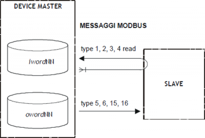
The MODBUS device can use a serial port or TCPIP to communicate in master mode (parameter mode = 0). Allows (via parameters, states and commands) all instruments to be able to communicate with any equipment utilizing Modbus.
The device provides a data exchange area where the QCL can write or read values shared with the slaves on the network. This area is represented by a list of parameters of the device divided into two groups to differentiate the type of access of the data by the device. The first section is identified as INPUT the second as OUTPUT. The INPUT section, for master operation, is the storage area of reads data. It is used by all reader functions (parameter type = 1, 2, 3 o 4). The OUTPUT section, in the master operation, is the area of data storage that the master should transfer to the slaves. It is used by all writing functions (parameter type = 5, 6, 15 o 16). To facilitate the exchange of data between devices, the structure of the Exchange area includes data types commonly used in QCL namely WORD, LONG and FLAG. The “BYTE” type does not appear because the modbus usually uses the word size for each address registers. The modbus protocol selects data based on the number of access log register, while the QCL selects based on the parameter symbol, you create a reference table in which each QCL symbol find the corresponding number in the register of access in Modbus protocol. To obtain greater flexibility for addressing, the same area of Exchange data can be manipulated by the QCL with different dimension parameterized. All the symbols that appear in the same row of the table refer to the same memory locations.
0.5.1 Input and coil Data Access
The data input or coil type have in the modbus Protocol a bit size. To store this information in the table of data exchange is defined as follows mode: each register (and then every word parameter of the device) represents 16 elements that are numbered from left to right. For the Scriptures or multiple readings when bits read are higher than those contained in the register the operation continues in the next register.
The st_ibit0… and st_obit1… states are useful in order to facilitate access to information bit, only in the first table log.
0.5.2 Mode of MASTER operation
The master mode is set with the mode parameter = 0. The card generates modbus messages only on QCL ordering and does not automatically. To “format” the modbus message string there are a number of parameters.
Using the two commands SEND or SENDSYC you send the read or write request to the slave, a number of States allow an audit on the operation being executed. We see in detail:
0.5.2.1 Parameters for formatting the message:
type = request type that you want to process (reading or writing word or bit).
idcard = address of the slave drive to which you want to send the request.
addr = the index from which to start reading or at which to start writing in the slave.
tabreg = for read operations (type = 1, 2, 3, 4), This parameter indicates the position in the “table of data read” where will store the read data on the slave. For write operations (type = 5, 6, 15, 16), this parameter indicates the position in the “table of data to be written” where is the data to be written on the slave. Are accepted values are between 1 and 512 for values of type parameter = 1, 2, 5, 15 (writing and reading of bits), while for type value = 3, 4, 6, 16 (writing and reading of word) the expected values are between 1 and 32.
num = number of values that are read or write (if the request type so provides). Are accepted values are between 1 and 128 for values of type parameter = 1, 2, (reading of bits), while for type value = 3, 4, 16 (multiple word reading and writing) the accepted value are between 1 and 32.
0.5.2.2 Commands to send the message:
SEND sends the request message to the slave.
SENDSYC sends the request message to a QEM slave of MODBUS type and reports the operation concluded (st_sended) only when the slave executes the RECEIVED command.
0.5.2.3 State variables for diagnostic operation:
When ended the message send operation, the status st_sended variable is set to 1. If you used the SEND command the state is set to 1 when the master receive the confirmation of the message being sent. If you have used the SENDSYC command in the master then this status will be set to 1 when the slave QEM will execute the RECEIVED command. In case of error, This status is still in set to 1 (After the toutsyc time) but the err parameter indicates the cause of the error (see the description of this parameter for details).
The SENDSYC coomand it becomes necessary when you want to synchronize master data packet writing by reading the same data from the slave (can be used when both master and slave are Qmove).
0.5.3 Read request
Read Coil
Bit read function. You want to read the bits of a slave (idcard). Sets the parameter type = 1.
You must set addr to indicate the address of the bit in the slave from which to start reading. The num parameter indicates the number of bits that are read. You must to set tabreg to indicate the index of the bit in the “data read table” the master from which you want to be written the read bits. The raedings value will be saved in the “data read table”. It is recommended to always meet the following two conditions:
(addr + num - 1) ⇐ 512 e (tabreg + num - 1) ⇐ 512 otherwise the request will fail (reporting by wcmd).
Read Input
Bit read function. To read the bits of a slave (idcard). The function is equal to the “Read Coil”. Sets the parameter type = 2.
The meaning of the two functions is distinguished at the level of MODBUS protocol. Some slave can make available different memory areas depending if the bits are Coil or Input. In the case of slave Qmove the two requests have the same effect.
Read Holding Register
Word read function. For reading the word of the slave (idcard). Sets the parameter type = 3.
You must to set addr to indicate the address of the word in the slave from which to start reading. The num parameter indicates the number of word to be read. You must set tabreg to indicate the index of the word in the “read data table” of the master from which you want are writes the read words. The read values will be saved in the “read data table”. It is recommended to always meet the following two conditions:
(addr + num - 1) ⇐ 32 e (tabreg + num - 1) ⇐ 32 otherwise the request will fail (reporting by wcmd).
Read Input Register
Word read function. For reading the bit of the slave (idcard). The function is equal to the “Read Holding Register”. sets the parameter type = 4.
The meaning of the two functions is distinguished at the level of MODBUS protocol. Some slave can make available different memory areas depending if the read word are Holding or Input. In the case of slave Qmove the two requests have the same effect.
0.5.4 Write request
Force coil
Bit write function. For writing (force) the bit of the slave (idcard). Sets the parameter type = 5.
You must set addr to indicate the address of the bit in the slave that you want to write. You must set tabreg to indicate the index of the bit in the “write data table” that contains the value to be written.
Force register
Word write function. For write (force) the word of a slave (idcard). Sets the parameter type = 6.
You must set addr to indicate the address of the word in the slave that you intend to write. You must set tabreg to indicate the index of the word in the “data write table” that contains the value to be written.
Force multiple coil
Multiples bit write function. For write (force) the bit of a slave (idcard). Sets the parameter type = 15.
You must set addr to indicate the address of the bit in the slave that you intend to write. You must set in num the number of bits to write. You must set tabreg to indicate the bit index of the “data write table” from which to begin the values to be written. It is recommended to always meet the following two conditions:
(addr + num - 1) ⇐ 512 e (tabreg + num - 1) ⇐ 512 otherwise the request will fail (reporting by wcmd).
Force multiple register
Multiples word write function. For write (forzare) the word of a slave (idcard). Sets the parameter type = 16.
You must set addr to indicate the address of the word in the slave that you intend to write. You must set in num the number of word to write. You must set tabreg to indicate the index of the word in the “dat write table” from which to begin the values to be written. It is recommended to always meet the following two conditions:
(addr + num - 1) ⇐ 32 e (tabreg + num - 1) ⇐ 32 otherwise the request will fail (reporting by wcmd).
0.5.5 Examples
1) Modbus settings and opening of serial communication
modbus.mode = 0                             ; modbus master
modbus.prot = 1                             ; RTU
modbus.brate = 57600                        ; baudrate
modbus.stopb = 1                            ; stop bits
modbus.par = 0                              ; parity
modbus.tout = 100                           ; timeout

modbus.OPENCOM
tm_opencom = 200                            ; timeout for OPENCOM command
WAIT modbus.st_opencom OR tm_opencom
IF NOT modbus.st_opencom
    OpenComError = 1                        ; com not opened
ENDIF
2) Impostazioni modbus e apertura del canale di comunicazione di tipo TCPIP
modbus.mode = 0                             ; modbus master
modbus.prot = 2                             ; TCPIP
modbus.tout = 100                           ; timeout

tcpip_port= 502                             ; number of tcpip port (default 502)
modbus.stopb = (tcpip_port ANDB &H0000FF00) / 256
modbus.par = tcpip_port ANDB &H000000FF

modbus.OPENCOM
tm_opencom = 500                            ; waiting time to have a correct response
WAIT tm_opencom
IF NOT modbus.st_opencom
    OpenComError = 1                        ; com not opened
ENDIF
3) Reading the registry input nr.7 of the slave id 67
modbus.idcard = 67
modbus.addr = 7
modbus.tabreg = 7
modbus.num = 1
modbus.type = 4
modbus.SEND
WAIT modbus.st_sended
IF (modbus.err)
    CALL ErrorModbus
ENDIF
slSpeed = modbus.iword7
4) Reading of the holding register from nr.600 to nr.606 of the slave id 8
The area of QCL data exchange does not support the address 600, you use the tabreg parameter to save the data read at 10 address
modbus.idcard = 8
modbus.addr = 600
modbus.num = 6
modbus.tabreg = 10
modbus.type = 3
modbus.SEND
WAIT modbus.st_sended
IF (modbus.err)
    CALL ErrorModbus
ENDIF

swTemp1 = modbus.iword10
slSpeed = modbus.ilong6
slPosiz = modbus.ilong7
swTemp1 = modbus.iword15
0.5.6 Block diagrams
0.5.7 Broadcast
The Broadcast is a special message that is sent by the Master and is received simultaneously from all connected slaves. The broadcast function (idcard = 0) is supported only in master mode and if you use a message with type = 5, 6, 15 and 16 (write only). In this mode the st_sended state is activated once ended the transmission and not on receipt of confirmation by the slave. There isn't answer on the slaves to such messages. You cannot use the SENDSYC command.
0.5.8 Slaves indentification
When the card works in master mode allows, with specila command, tell if the slave connected is a QEM. If so also determines the pattern of slave connected. This allows a diagnostic on the correct network configuration. You cannot extend this control to all types of existing slaves because the protocol does not provide a standard way of slave recognition.
The READSTYPE command executed after selecting the slave (through idcard parameter) send a nr.17 modbus request to the slave for recognition. The slave will responds with a default value and can be read in the stype parameter of the master. If the slave is not produced by QEM, the parameter will be –1 value to indicate that the slave is connected but you cannot identify it.
For the MODBUS device the ID slave is different depending on the slave QEM used. For encoding of the slaves see the slave Firmware used.
Example of slave identification nr.12:
modbus:idcard = 12
modbus.READSTYPE
WAIT modbus.st_sended
IF (modbus.err)
    sbConfig = 3             ; error: slave 12 not connected
ELSE
    IF (modbus.stype EQ 1)   ; Board CAM-AG-98
        sbConfig = 1         ; configuration OK
    ELSE
        sbConfig = 2         ; error in network configuration
    ENDIF
ENDIF
0.5.9 Protocol extension
The modbus standard communication protocol defines 4 types of Exchange data:
-
INPUT STATUS,
-
COIL STATUS,
-
INPUT REGISTER,
-
HOLDING REGISTER.
These 4 types treat signals as Digital Inputs, Digital Outputs, Analog Inputs, and Analog Outputs. The values of the registers (INPUT REGISTERS and HOLDING REGISTERS), are defined as values in 16 bit, each with a unique address, (example INPUT REGISTER #1, INPUT REGISTER #2, INPUT REGISTER #3, ecc.).
To allow support for datatypes larger than 16 bit, has been designed an extension to the protocol to treat long 32 bit dimension values. Implementing this feature preserves the formatting of the message standard modbus it uses the contents of two consecutive addresses to represent a 32 bit value. When this extension is enabled (wider = 1), depending on the address used the slave responds with a 16-bit or 32-bit value for each log request. If the address is greater than 5000 will be returned a 32-bit value, if under the Protocol remains unchanged with response to 16 bits.
0.5.10 Commands and parameters
0.5.10.1 Used symbols
The parameter name, condition or command is taken back to the left side of the table.
R
Indicates if the parameter or state is retentive (upon initialization of the device maintains the previously defined state), or the state assumes upon initialization of the device.
If the device does not need to initialize the “R” field indicates the value that the parameter or state take at the at power-up card.
R = Retentive
0 = Upon initialization of the device the value is forced to zero.
1 = Upon initialization of the device the value is forced to one.
- = Upon initialization of the device is presented significant value.
D
Indicates the size of the parameter.
F = Flag
B = Byte
W = Word
L = Long
S = Single Float
Conditions
Describes all the conditions necessary for the parameter so that the parameter is considered correct or because the command is accepted.
In some cases, limit values are specified for the acceptance of the parameter: if any values outside the limits set are introduced, the data is however accepted; therefore appropriate controls of the application must be provided to ensure the proper functioning.
To execute a command, all conditions must be met; otherwise the command does not execute.
A
Indicates the access mode.
R = Read.
W = Write.
RW = Read / Write.
0.5.10.2 Parameters
| Name | D | R | A | Conditions | Description |
|---|---|---|---|---|---|
| mode | B | R | R/W | - | Mode (0 ÷ 2) Defines if the board should function as a master or slave. 0 = master. |
| prot | B | R | R/W | - | Protocol (0 ÷ 1) Defines the type of modbus protocol to use. 0 = ASCII, 1 = RTU, 2 = TCPIP |
| wider | B | R | R/W | - | Wide Registers (0 ÷ 1) Indicates if to use the 32-bit registers protocol extension. See the “Extension of the Protocol” section : 0 = normal, 1 = extended protocol. |
| idcard | W | R | R/W | - | Identification Card (0 ÷ 255) In the operation as the master is the device number that you want to transmit. In master mode setting of zero is also valid for operation broadcast. |
| type | B | 1 | R/W | - | Type Defines the type of request that the master must perform. Allowed values: 1, 2, 3, 4, 5, 6, 15, 16 |
| addr | L | 1 | R/W | - | Address (1 ÷ 65535) Defines the address used by the master to define the data to be read or write. |
| tabreg | W | 1 | R/W | - | Destination (1 ÷ 512) Defines the address data tables into which to write the data read or where to find the data to write. |
| num | W | 1 | R/W | - | Number (1 ÷ 512) Is the number of items to be written to or read in the request of the master. |
| brate | L | R | R/W | - | Baud rate Serial Baud rate. Allowed values: 4800, 9600, 19200, 38400, 57600, 115200. |
| stopb | B | R | R/W | - | Stop bit Allowed values: 1, 2. |
| par | B | R | R/W | - | Parity (0 ÷ 2) 0 = none, 1 = odd, 2 = even. |
| tout | W | R | R/W | - | Timeout (0 ÷ 9999 msec) For the master mode is the maximum time the slave must respond. Setting it to zero, the Timeout is disabled. |
| toutsyc | W | R | R/W | - | Time out synchronize (0 ÷ 9999 msec) Only used to master mode is the maximum time that can elapse between sending the SENDSYC command and the RECEIVED command execution on the QEM slave. |
| iword1÷32 | W | 0 | R | - | Input Word nr. (1Input Long nr. (1÷16)32) |
| st_ibit0÷15 | F | 0 | R | - | Input bit in the iword1 parameter |
| ilong1÷16 | L | 0 | R | - | Input Long nr. (1÷16) |
| oword1÷32 | W | 0 | R/W | - | Output Word nr. (1÷32) |
| st_obit0÷15 | F | 0 | R/W | - | Output bit in the oword1 parameter |
| olong1÷16 | L | 0 | R/W | - | Output Long nr. (1÷16) |
The ability to communicate with the TCPIP protocol It was developed at a later time than the birth of the MODBUS device. For this reason the IP address and port setting is achieved using some parameters that have a different meaning.
To configure the TCPIP port number You must go and write about the stopb and par parameters. Respectively :
-
stopb = tcpip_port / &H00000100
-
par = tcpip_port ANDB &H000000FF
To set the TCPIP slave to which you want to execute the request you must go to write on thebrate parameter .
An IP address can be expressed as TcpAddr3.TcpAddr2.TcpAddr1.TcpAddr0 (for example 192.168.0.1).
-
brate = (TcpAddr3 * &H01000000) + (TcpAddr2 * &H00010000) + (TcpAddr1 * &H00000100) + TcpAddr0
0.5.10.3 Variables
| Name | D | R | A | Conditions | Description |
|---|---|---|---|---|---|
| err | B | 0 | R | - | Errors Indicates if errors occurred in the protocol. In master mode the parameter is updated to coincide the activation of the st_sended state. The values from 1 to 49 are those sent by the slave. Values greater than 50 are generated internally by the master. The first 8 velues are normalized in the protocol and are: 0 = communications without errors, 1 = ILLEGAL FUNCTION, 2 = ILLEGAL DATA ADDRESS, 3 = ILLEGAL DATA VALUE, 4 = SLAVE DEVICE FAILURE, 5 = ACKNOWLEDGE, 6 = SLAVE DEVICE BUSY, 7 = NEGATIVE ACKNOWLEDGE, 8 = MEMORY PARITY ERROR, 50 = UNKNOWN RECEIVED ERROR the slave answered with a code greater than 49, 51 = TIMEOUT the slave does not respond within the time scheduled in the tout parameter, 52 = INVALID ANSWER, 52 = INVALID FUNCTION ANSWER - Function type not supported, 53 = CHECKSUM ANSWER - The checksum proceeds does not match, 54 = TRUNCATED ANSWER - Message too short, 55 = INVALID ID ANSWER - Slave ID mismatch, 56 = INVALID_MBAP_TRANSACTION_ID - modbus TCPIP, transaction ID incorrectly, 57 = INVALID_MBAP_PROTOCOL_ID - modbus TCPIP, protocol ID different by zero, 70 = TIMEOUT SYNCHRONIZED the slave QEM did not execute the RECEIVED command within the time scheduled in the toutsyc parameter. In slave mode the parameter is never updated. |
| serr | B | 0 | R/W | - | Serial Errors Indicates if errors occurred in serial communication. The parameter is updated for each error encountered. The value persists until: - under a subsequent error; - the writing of one of the following parameters: mode, prot, wider, brate, stopb, par; - writing about himself (any value will reset). 0 = no errors, 1 = parity error, 2 = framing error, 3 = overrun error. |
| stype | W | 0 | R | - | Slave type Indicates the type of slave connected. The parameter is updated when the st_sended parameter becomes 1 and if it had been execute a READSTYPE command |
0.5.10.4 States
| Name | D | R | A | Conditions | Description |
|---|---|---|---|---|---|
| st_sended | F | 0 | R | - | Sended State only been used in master mode. Activation indicates completion of the transmission of a message. The state is reset with the SEND or SENDSYC commands. |
| st_opencom | F | 0 | R | - | Open communication port Activation indicates that the device is working the serial communications port. To set this state use the OPENCOM command, to reset CLOSECOM. |
| wdata | F | 0 | R | - | Warning Data This bit indicates that an attempt was made to insert an invalid value in a parameter. |
| wcmd | F | 0 | R | - | Warning Command This bit indicates that it did not execute a command because they missing the necessary conditions. |
0.5.10.5 Commands
The available commands to manage the device are listed below in descending order of priority.
The device executes all commands received within the same sampling time starting from the one with the highest priority.
For example if the device receives the same sampling time CLOSECOM and OPENCOM commands, first run the OPENCOM command and then to CLOSECOM leaving therefore the communication port closed.
| Name | D | R | A | Conditions | Description |
|---|---|---|---|---|---|
| SEND | - | - | - | mode = 0 0 < num ⇐ 128 st_sended = 1 st_opencom = 1 | Sended Determines the message transmission toward the slave select. |
| SENDSYC | - | - | - | mode = 0 0 < num ⇐ 128 st_sended = 1 st_opencom = 1 | Send synchronize Usable only in master mode determines the message transmission towards a slave QEM with synchronisation. |
| READSTYPE | - | - | - | mode = 0 st_sended = 1 st_opencom = 1 | Read slave type Read information request type specified on the idcard slave. The answer will be reported on the stype parameter when the st_sended state becomes 1. |
| CLRWDATA | - | - | - | - | Clear Warning Data Reset the wdata parameter reporting. |
| CLRWCMD | - | - | - | - | Clear Warning Command Reset the wcmd parameter reporting. |
| OPENCOM | - | - | - | st_opencom = 0 | Open Serial communication\ Open the serial communication (the device then committed the communications port ). The st_opencom status becomes 1. |
| CLOSECOM | - | - | - | - | Close Serial communication Close the serial communication (the device then does not committted the communications port ). The st_opencom status becomes 0. |
0.6 Slave operation description
0.6.1 Slave mode operation
Slave mode is set with the mode = 1 or mode = 2 parameter. You must to introduce in the parameters the slave ID code through the idcard parameter.
Modbus settings and opening channel of serial communication
modbus.mode = 1                             ; modbus slave
modbus.prot = 1                             ; RTU
modbus.brate = 57600                        ; baudrate
modbus.stopb = 1                            ; stop bits
modbus.par = 0                              ; parity
modbus.idcard = 1                           ; slave id

modbus.OPENCOM
tm_opencom = 100                            ; timeout for OPENCOM command
WAIT modbus.st_opencom OR tm_opencom
IF NOT modbus.st_opencom
    OpenComError = 1                        ; com not opened
ENDIF
Modbus settings and open of the communication channel of TCPIP type
modbus.mode = 1                             ; modbus slave
modbus.prot = 2                             ; TCPIP

tcpip_port= 502                             ; number of tcpip port (default 502)
modbus.stopb = (tcpip_port ANDB &H0000FF00) / 256
modbus.par = tcpip_port ANDB &H000000FF

modbus.OPENCOM
tm_opencom = 100                            ; waiting time to have a correct response
WAIT (modbus.st_opencom OR timerOpencom)
IF NOT modbus.st_opencom
    OpenComError = 1                        ; com not opened
ENDIF
The operations that should execute the QCL are essentially two:
-
update the parameters owordNN, olongNN type (which will then be read from the master)
-
process the parameters iwordNN, ilongNN type (which will then written by the master)
0.6.1.1 Updating owordNN parameters type
To update the owordNN parameters type the QCL must write values in the parameters then send the VALIDATE command. The use of the command is necessary to make available on the readings of the master the new data at the same time, so that they can be read only part of updated parameters. So assigning a value to a device parameter DOES NOT MEAN that it is immediately available for the master readings. Will only be available after the VALIDATE command.
Example
modbus.olong1 = anpos.speed
modbus.oword1 = npezzi
modbus.oword2 = npezzitot
modbus.oword3 = anpos.dir
modbus.olong2 = anpos.posit
modbus.VALIDATE
0.6.1.2 Process iwordNN parameters type
To process the iwordNN parameters type, instead,the QCL must wait for the st_msgrx state is activated. This means that a write message was sent by the master. For the read message no signal reportedly to QCL parameters. The QCL then must take the values from the data exchange and at the end needs to send the RECEIVED command, only then the st_msgrx state is disabled.
Example
WAIT modbus.st_msgrx
anpos.speed = modbus.ilong1
anpos:posit = modbus.ilong2
npezzi = modbus.iword1
RECEIVED modbus
There is no control to prevent when reading iwordNN parameters the master incorrectly execute another writing, before the project code present in the slave to finish the process.
Also the code for handling the modbus device in the application it is recommended that it is collected in a single task in order not to create simultaneous accesses to the device that could generate invalid conditions.
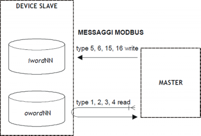
All read requests that arrive from the master MODBUS refer to the owordNN type data by accessing to the same data area. The slave provides the values that the master will read in the owordNN parameters type.
All write requests arriving from the MODBUS master refer to the iwordNN type data aby accessing to the same data area. The slave provides the iwordNN parameters where the master will write data.
0.6.2 Block diagram
0.6.3 Commands and parameters
0.6.3.1 Simbologia adottata
Il nome del parametro, stato o comando è riportato alla sinistra della tabella.
R
Indica se il relativo parametro o stato è ritentivo (al momento dell’inizializzazione del device mantiene lo stato precedentemente definito), oppure lo stato che assume al momento dell’inizializzazione del device.
Se il device non necessita di inizializzazione il campo “R” indica il valore che il parametro o stato assume all’accensione della scheda.
R = Ritentivo
0 = Al momento dell’inizializzazione del device il valore è forzato a zero.
1 = Al momento dell’inizializzazione del device il valore è forzato ad uno.
- = Al momento dell’inizializzazione del device è presentato il valore significativo.
D
Indica la dimensione del parametro.
F = Flag
B = Byte
W = Word
L = Long
S = Single Float
Condizioni
Sono descritte tutte le condizioni necessarie affinché il parametro sia considerato corretto o perché il comando venga accettato.
In alcuni casi sono specificati dei valori limite per l’accettazione del parametro: se sono introdotti dei valori esterni ai limiti impostati, il dato è comunque accettato; pertanto devono essere previsti opportuni controlli dell’applicativo tali da garantire il corretto funzionamento.
Per l’esecuzione di un comando, tutte le relative condizioni devono necessariamente essere soddisfatte; in caso contrario il comando non è eseguito.
A
Indica la modalità d'accesso.
R = Read (lettura).
W = Write (scrittura).
RW = Read / Write.
0.6.3.2 Parametri
| Nome | D | R | A | Condizioni | Descrizione |
|---|---|---|---|---|---|
| mode | B | R | R/W | - | Mode (0 ÷ 2) Definisce se la scheda deve funzionare come master o come slave. 1 = slave con area di scambio dati fissa; 2 = slave senza area di scambio dati fissa: ad ogni scrittura o lettura eseguita dal master viene messi a 1 il flag st_msgrx. Contemporaneamente i parametri type, addr e num indicano le caratteristiche del messaggio ricevuto. - Type indica il tipo di funzione che vuole fare ill master (lettura o scrittura), - addr indica l'indirizzo dell'inizio del blocco di dati scritti o letti, - num indica il numero di dati letti o scritti (a bit o a byte a seconda del valore di type). Il device controllerà, in ricezione, solamente num (size di messaggio) che non sia superiore a 32word ma non più l'indirizzo che può essere ora qualsiasi. Se è una scrittura (lo si capisce dal valore di type se è 5,6,15,16) vengono riportati i dati nelle variabili di scambio input (sempre a partire dalla prima word) ed il device attende il comando RECEIVED. Se è una lettura il device attende che il QCL depositi i dati nelle word variabili di scambio output ed attende il comando VALIDATE. |
| prot | B | R | R/W | - | Protocol Definisce il tipo di protocollo Modbus da utilizzare. 0 = ASCII, 1 = RTU, 2 = TCPIP. |
| wider | B | R | R/W | - | Wide Registers Indica se utilizzare l’estensione del protocollo per i registri a 32bit. Vedere capitolo “Estensione del protocollo”. 0 = normale, 1 = protocollo esteso. |
| idcard | W | R | R/W | - | Identification Card ( 1 ÷ 255 per slave) Nel funzionamento come slave è il numero che identifica l’apparecchio nella rete. |
| brate | L | R | R/W | - | Baud rate Baud rate della seriale. Valori validi: 4800, 9600, 19200, 38400, 57600, 115200. |
| stopb | B | R | R/W | - | Stop bit Valori validi: 1, 2. |
| par | B | R | R/W | - | Parity (0 ÷ 2) 0 = none, 1 = even, 2 = odd. |
| rdelay | W | R | R/W | - | Reply delay (0 ÷ 9999 msec) E' il tempo di attesa prima di trasmettere la risposta. |
| iword1÷32 | W | 0 | R | - | Input Word nr. (1Input Long nr. (1÷16)32) |
| st_ibit0÷15 | F | 0 | R | - | Input bit nel parametro iword1 |
| ilong1÷16 | L | 0 | R | - | Input Long nr. (1÷16) |
| oword1÷32 | W | 0 | R/W | - | Output Word nr. (1÷32) |
| st_obit0÷15 | F | 0 | R/W | - | Output bit nel parametro oword1 |
| olong1÷16 | L | 0 | R/W | - | Output Long nr. (1÷16) |
0.6.3.3 Variabili
| Nome | D | R | A | Condizioni | Descrizione |
|---|---|---|---|---|---|
| serr | B | 0 | R/W | - | Serial Errors Indica se sono stati riscontrati errori nella comunicazione seriale. Il parametro viene aggiornato ad ogni errore rilevato. Il valore permane fino ad un successivo errore o ad una scrittura sullo stesso con il QCL. 0 = nessun errore, 1 = parity error, 2 = framing error, 3 = overrun error. |
0.6.3.4 Stati
| Nome | D | R | A | Condizioni | Descrizione | |
|---|---|---|---|---|---|---|
| st_msgrx | F | 0 | R | - | Message received Stato utilizzato solo in modalitá slave. Indica che un messagio del master ha eseguito una scrittura nell’area scambio dati QCL. Lo stato viene resettato con il comando RECEIVED. |
|
| st_opencom | F | 0 | R | - | Open communication port L'attivazione indica che il device sta impegnando la porta di comunicazione seriale. Per settare questo stato usare il comando OPENCOM, per resettarlo CLOSECOM. | |
| wdata | F | 0 | R | - | Warning Data Questo bit segnala che è stato tentato un inserimento di un valore non valido in un parametro. | |
| wcmd | F | 0 | R | - | Warning Command Questo bit segnala che è non è stato eseguito un comando perchè mancano le condizioni necessarie. | |
0.6.3.5 Comandi
I comandi a disposizione per gestire il device sono elencati sotto in ordine di priorità decrescente.
Il device esegue tutti i comandi ricevuti entro lo stesso tempo di campionamento iniziando da quello con la priorità maggiore.
Per esempio se il device riceve nello stesso tempo di campionamento i comandi CLOSECOM e OPENCOM, per primo esegue il comando OPENCOM e poi quello di CLOSECOM lasciando perciò la porta di comunicazione chiusa.
| Nome | D | R | A | Condizioni | Descrizione |
|---|---|---|---|---|---|
| RECEIVED | - | - | - | st_msgrx = 1 mode = 1, 2 st_opencom = 1 | Received Utilizzato solamente in modalitá slave. Indica che l’applicativo QCL ha processato le informazioni che il master ha inviato |
| VALIDATE | - | - | - | mode = 1, 2 st_opencom = 1 | Validate Indica che i parametri di scambio dati QCL diventano disponibili al master. |
| CLRWDATA | - | - | - | - | Clear Warning Data Azzera la segnalazione del parametro wdata |
| CLRWCMD | - | - | - | - | Clear Warning Command Azzera la segnalazione del parametro wcmd |
| OPENCOM | - | - | - | st_opencom = 0 | Open Serial communication Apre la comunicazione seriale (il device quindi impegna la porta di comunicazione). Lo stato st_opencom diventa 1. |
| CLOSECOM | - | - | - | - | Close Serial communication Chiude la comunicazione seriale (il device quindi non impegna piú la porta di comunicazione). Lo stato st_opencom diventa 0. |
0.7 Migrazione dal device MODBUS01 al device MODBUS
Il primo aspetto da tenere presente per la migrazione è il fatto che il device MODBUS01 è esterno mentre il MODBUS è
interno. Questo implica che la dichiarazione del device deve essere eseguita nella sezione “INTDEVICE” dell’unità di
configurazione del progetto. Inoltre, questo comporta la scelta, durante la definizione del device MODBUS, del tempo di
campionamento. Il valore del tempo di campionamento che mantiene inalterate le prestazioni della comunicazione tra i
due device è pari a 5 ms. Bisogna inoltre, in fase di definizione, selezionare la seriale da impegnare.
Il device MODBUS ha aumentato il numero di variabili di scambio (da 16 word a 32 word) ma questo non influenza il funzionamento
per le impostazioni che utilizzano al massimo 16 word come sono quelle pensate per il device MODBUS01.
Il device MODBUS ha limitato la variabile “num” a 128, mentre per il device MODBUS01 il limite è 256. Questo si è reso
necessario per permettere un’ottimizzazione del tempo di campionamento. La scelta è stata presa in considerazione del
fatto che tali valori venivano impiegati unicamente per la gestione dei Coils, ma che perdeva di logica la lettura/scrittura di
più di 128 coils consecutivi.
Il device MODBUS consente di controllare (mediante 2 nuovi comandi) l'impegno della seriale di comunicazione da parte
del device. Questa nuova funzionalitá è interessante nell'eventualità che in un progetto Qview siano stati dichiarati altri
devices che possono utilizzare la stessa seriale.
Se un applicativo era stato scritto per il device MODBUS01 bisogna aggiungere il comando OPENCOM (eseguito anche
solo una volta) come mostrato nel seguente esempio.
Esempio:
; impostazione dei parametri di comunicazione
modbus.mode = 0
modbus.brate = 38400
...
modbus.OPENCOM
WAIT modbus.st_opencom

modbus.idcard = 8
modbus.addr = 600
modbus.num = 6
modbus.tabreg = 10
modbus.type = 3
modbus.SEND
WAIT modbus.st_sended
IF (modbus.err)
    CALL ErroreModbus
ENDIF