This is an old revision of the document!
OT11PidReg
O = Digital output
T = Control functions
The OT11PidReg function implements a PID controller to temperature (heating only) with self-tuning function.
IMPLEMENTATION
OT11PidReg ( aswParReg , aswParUsr, gwSetPoint, gwMeasure, gfEnaReg, agwOutReg )
Parameters:
| IN/OUT | VARIABLE TYPE | EXAMPLE NAME | DIM | |
|---|---|---|---|---|
| IN | ARRSYS | aswParReg [1] | W | Sample time PID controller (msec) [0÷32767]. |
| IN | ARRSYS | aswParReg [2] | W | Maximum scale limit of the process variable (UM) [-32768÷32767] |
| IN | ARRSYS | aswParReg [3] | W | Minimum scale limit of the process variable (UM) [-32768÷32767] |
| IN | ARRSYS | aswParReg [4] | W | Maximum value of control output [1÷32767] |
| IN | ARRSYS | aswParReg [5] | W | Minimum value of control output [0÷32767] |
| IN | ARRSYS | aswParUsr [1] | W | Proportional band.(‰ )[0÷1000] |
| IN | ARRSYS | aswParUsr [2] | W | Integral time (min x 100) [0÷9999] |
| IN | ARRSYS | aswParUsr [3] | W | Derivative time (min x 100) [0÷9999] |
| IN | ARRSYS | aswParUsr [4] | W | Sample time of the derivative [0÷255] 0=sample time PID controller 1=2*sample time PID controller . . n=(n+1)*sample time PID controller |
| IN | ARRSYS | aswParUsr [5] | RW | Tuning mode[0÷2] 0=no 1=self-tuning at next reboot 2=self-tuning the next time start adjusting |
| IN | GLOBAL | gwSetPoint | W | Temperature setpoint (UM) |
| IN | GLOBAL | gwMeasure | W | Value of the process variable (UM) |
| IN | GLOBAL | gwEnaReg | F | Enabling regulation [0÷1] 0=regulator disabled 1=regulator enabled |
| OUT | ARRGBL | agwOutReg[1] | W | PID output log |
| OUT | ARRGBL | agwOutReg[2] | W | Proportional output log |
| OUT | ARRGBL | agwOutReg[3] | W | Integral output log |
| OUT | ARRGBL | agwOutReg[4] | W | Derivative output log |
| OUT | ARRGBL | agwOutReg[5] | W | Adjusting digital output status |
| OUT | ARRGBL | agwOutReg[6] | W | Error code |
Errors
After calling the function, the “error code” variable in agwOutReg[6] takes certain values, the meaning of these values is summarized below:
0: No error
1: Error setting sampling time
2: Error setting lower limit and/or greater of scale
3: Error setting the proportional band
4: Error setting integration time
5: Error setting derivative time
6: Error setting minimum and/or maximum value regulator output
7: Error setting sampling time derivative
Example
;---------------------------------------------
; Project           : REG_012
; Module Name       : PIDREG
; Author            :
; Description       : PID regulator
;---------------------------------------------
	aswParReg [0]=500			; sampling time = 500ms
	aswParReg [1]=10000			; full scale over temperature = 1000.0 °C
	aswParReg [2]=0				; full scale ower temperature = 0.0 °C
	aswParReg [3]=500			; Maximum value output regulator = 500
	aswParReg [4]=0				; Minimum value output regulator = 0

        gfEnaReg = 1				;Enable Adjusting
MAIN:
	gwSetPoint = 800
        gwMeasure = glTemperatura		;Passes the measured temperature in UM
        OT11PidReg ( aswParReg , aswParUsr, gwSetPoint, gwMeasure, gfEnaReg, agwOutReg )
	IF agwOutReg[5] EQ 0
		RESOUT ofOutPow
	ELSE
		SETOUT ofOutPow
	ENDIF

WAIT 1
JUMP MAIN
Definition of regulator
A regulator reads an input signal process variable / measure), compares it to a reference signal (setpoint) and change the value of the process variable to achieve equality with the setpoint.
PID regualtor
One of the most popular types of regulators is the PID (Proportional, Integral, Derivative).
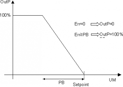
Proportional action
Provides a contributes, at the output, proportional to the error between the setpoint and measurement. The coefficient of proportionality is said “proportional Constant” (Kp)
OutP(t) = Kp*err(t)
Very often, instead of proportional coefficient is used the “proportional Band” defines as:
Kp=100/PB
Expressing variables as a percentage of full scale, PB is the error signal amplitude (setpoint-measure) able to bring the output proportional to the 100%.
The only proportional controller fails to clear the error in scheme, remains a small difference between the setpoint and measurement. If PB increases the error in steady increases, when PB decreases the error in steady decreases. Too small values of PB can bring the system into oscillation.
Integral action
Provides a contributes, at the output, proportional to the integral of the error. In hypothetical conditions of constant error, the integral output increases linearly and reaches the proportional output value after the integral time.
OutI(t) = 1/Ti*∫err(t)
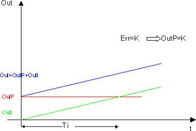
The integral is used, in combination with the proportional, to eliminate the error.
Azione derivativa
Fornisce un contributo, all'uscita, proporzionale alla derivata dell'errore. In ipotetiche condizioni di errore crescente linearmente (quindi la sua derivata è costante), l'uscita proporzionale aumenta linearmente e raggiunge il valore dell'uscita derivativa dopo il tempo derivativo.
OutD(t) = Td*Δerr(t)/Δt
Funzione di Self-Tuning
Il regolatore PID comprende anche la procedura di self-tuning che permette di calcolare in maniera automatica il valore ottimale dei parametri di regolazione PID in fase di avviamento del processo. E' perciò importante eseguire la procedura quando la temperatura misurata è prossima a quella dell'ambiente (temperatura di equilibrio in assenza di potenza).
La funzione attiva il massimo di potenza impostata fino al raggiungimento del valore intermedio tra la temperatura iniziale ed il set-point, quindi azzera la potenza. La funzione valuta la risposta del sistema, quindi, dall'ampiezza della sovraelongazione e dal tempo che intercorre tra l'azzeramento della potenza ed il picco di temperatura, calcola i parametri PID.
Al termine della valutazione della risposta la funzione si autodisabilita ed il regolatore inizia la regolazione con i nuovi parametri per il raggiungimento del set-point impostato.
Come attivare la funzione di selftuning (modo 1 attivazione all'accensione):
-
Disabilitare la regolazione (variabile gwEnaReg=0)
-
Impostare il setpoint al valore desiderato
-
Assicurarsi che la temperatura sia prossima alla temperatura ambiente
-
Abilitare la funzione di selftuning impostando il parametro aswParUsr [5] al valore 1
-
Spegnere lo strumento (oppure eseguire un RESTART)
-
Riaccendere lo strumento (oppure mandare in RUN l'applicativo)
-
Abilitare la regolazione
Come attivare la funzione di selftuning (modo 2 attivazione all'inizio della regolazione):
-
Disabilitare la regolazione (variabile gwEnaReg=0)
-
Impostare il setpoint al valore desiderato
-
Assicurarsi che la temperatura sia prossima alla temperatura ambiente
-
Abilitare la funzione di selftuning impostando il parametro aswParUsr [5] al valore 2
-
Abilitare la regolazione
N.B Durante il selftuning il valore del parametro aswParUsr [5] assume i seguenti valori per indicare lo stato: -
Attesa temperatura al setpoint
-
Attesa che la temperatura finisca di crescere
-
Attesa che la temperatura inizi a decrescere
-
Fasi finali di calcolo