P1R31FG30 - 002Q : Connections and Setup
1. Informations
1.1 Release
This document is entirely valid except for errors or omissions.
| Release | Description | Date |
|---|---|---|
| 1.0 | New manual. | 29/04/15 |
1.1.1 Specifications
The copyright of this manual is reserved. No part of this document may be copied or reproduced in any form without the prior written authorization of QEM.
QEM does not have insurance or guarantees about the contents and specifically disclaims any liability relating to warranties of fitness for any particular purpose. The information in this document is subject to change without notice. QEM assumes no responsibility for any errors that may appear in this document.
Trademarks:
-
QEM® is a registered trademark.
-
Microsoft® and MS-DOS® are registered trademarks and Windows is a trademark of Microsoft Corporation.
2. Description
The application P1R31FG30 - 002, installed hardware Qmove C1-R31-FG30 and A1-HMI-QC104-03 / TP04 / G16 / 24V, is designed to control a machine bridge saw. Here are the main features of the software P1R31FG30 - 002.
2.1 Features
-
Control of 4-axis analog to independent movements and interpolated.
-
Touchscreen functionality for input data and actions via buttons.
-
Messaging support operator.
-
Messaging alarm.
-
Machining pre-established for the milling and cutting slabs of stone with CAD and CAM functionality integrated in the instrument.
3. Hardware and connections
The models of the devices used for this application are the following:
-
A1-HMI-QC104-03/TP04/G16/24V: terminal operator 10.4 “touch screen, 256 colors;
-
C1-R31FG30: CPU unit of motion control and automation logic.
For proper mechanical and electrical installation of the devices is recommended to follow the instructions in the corresponding instruction manuals and maintenance.
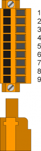
3.0.1 A1-HMI-QC104-03/TP04
Terminal operator.
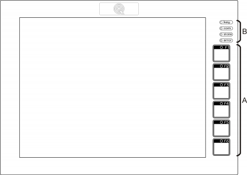 |
| Film standard QEM with function keys (A) and system LED (B) |
 |
| Rear view and socket arrangement |
3.0.2 C1-R31-FG30
Unit CPU motion control and logic of the automation.
 |
| View side connectors |
3.0.3 List I/O
In this chapter we list all the inputs and outputs used and divided by the connector. For a more detailed description of some of the I / O lists, see in later chapters which describes each connector.
The numbering of the connectors mentioned in the tables refers to devices
-
C1-R31FG30 - 1MG8F card;
-
A1-HMI-QC104-03/TP04/G16/24V.
3.0.3.1 Digital inputs
| System: C1-R31FG30 | |||
|---|---|---|---|
| Name | Function | Activation 1) | Terminal |
| I01 | FC Y maximum | OFF | CN11 |
| I02 | FC Y minimum | OFF | |
| I03 | Motor driver disk fault | OFF | |
| I04 | Disc motor running | ON | |
| I05 | Disc motor in stop | ON | |
| I06 | Auxiliary OK | ON | |
| I07 | Air disc motor and thermal OK | ON | |
| I08 | Thermal engine oil pump OK | ON | |
| I09 | Barrier closed | ON | CN12 |
| I10 | Pressure water present | ON | |
| I11 | Enabling tilting bench | ON | |
| I12 | Motor Driver X fault | OFF | |
| I13 | Y motor driver in fault | OFF | |
| I14 | Driver V engine in fault | OFF | |
| I15 | Driver Motor Z in fault | OFF | |
| I16 | Motor Driver C in fault | OFF | |
| I17 | FC X maximum | OFF | CN13 |
| I18 | FC X minimum | OFF | |
| I19 | FC Z maximum | OFF | |
| I20 | FC Z minimum | OFF | |
| I21 | FC C maximum | OFF | |
| I22 | FC C minimum | OFF | |
| I23 | Low oil level | OFF | |
| I24 | reserve | ||
| … | … | CN14 | |
| I30 | reserve | ||
| I31 | Selector speed spindle blade | ON | |
| I32 | Selector tool spindle speed | ON | |
OFF: open contact;
ON: closed contact
| System: A1-HMI-QC104-03/TP04/G16/24V | |||
|---|---|---|---|
| Name | Function | Activation 1) | Terminal |
| I33 | RESET button automatic cycle | ON | CN11 |
| I34 | STOP automatic cycle (HOLD) | OFF | |
| I35 | Jog button forward X | ON | |
| I36 | Button jog back X | ON | |
| I37 | Y jog button forward | ON | |
| I38 | Button jog back Y | ON | |
| I39 | Phase A Flyer | - | |
| I40 | Phase B Flyer | - | |
| I41 | Jog forward button Z | ON | CN12 |
| I42 | Jog back button Z | ON | |
| I43 | Button climb tilting bench | ON | |
| I44 | Button-down tilting bench | ON | |
| I45 | Start button | ON | |
| I46 | reserve | ||
| I47 | Phase A reserve | ||
| I48 | Phase B reserve | ||
OFF: open contact;
ON: closed contact
3.0.3.2 Digital outputs
| System: C1-R31FG30 | |||
|---|---|---|---|
| Name | Function | Activation 1) | Terminal |
| O01 | Enabling spindle | ON | CN7 |
| O02 | Activation by-pass safety barriers | ON | |
| O03 | Turning oil pump for tilting bench | ON | |
| O04 | Enabling EV water cooling | ON | |
| O05 | Laser activation | ON | |
| O06 | Alarm in progress | OFF | |
| O07 | Lamp presence alarm | ON | |
| O08 | Enabling EV climb bench | ON | |
| O09 | Enabling EV descent bench | ON | CN8 |
| O10 | Enable drive axis X | ON | |
| O11 | Enable drive axis Y | ON | |
| O12 | Enable drive axis V | ON | |
| O13 | Enable drive axis Z | ON | |
| O14 | Enable drive axis C | ON | |
| O15 | Signaling axis in motion | ON | |
| O16 | Reset driver | ON | |
| O17 | Selection rotating disk (OFF) or cutter (ON)OFF/ON | CN9 | |
| O18 | Activation lubrication | ON | |
| O19 | reserve | ||
| … | reserve | ||
| O24 | reserve | ||
| O25 | reserve | CN10 | |
| … | reserve | ||
| O32 | reserve | ||
OFF: open contact;
ON: closed contact:
B: flashing
| System: A1-HMI-QC104-03/TP04/G16/24V | |||
|---|---|---|---|
| Name | Function | Activation 1) | Terminal |
| O33 | Lamp automatic cycle stopped | ON | CN15 |
| O34 | Lamp disk in motion with cycle stop | B | |
| O35 | Lamp automatic cycle in progress | ON | |
| O36 | Bypass safety barriers Active | ON | |
| O37 | Lamp (or beep) alarm in progress | B | |
| O38 | Auxiliary lamp lit and ready CN | ON | |
| O39 | reserve | ||
| O40 | reserve | ||
OFF: open contact;
ON: closed contact:
B: flashing
3.0.3.3 Bidirectional counter inputs
| System: C1-R31FG30 | ||
|---|---|---|
| Name | Function | Terminal |
| CNT01 | Axis X | CN15 |
| CNT02 | Axis Y | CN16 |
| CNT03 | Axis Z | CN17 |
| CNT04 | Axis V | CN18 |
| CNT05 | Axis C | CN19 |
| CNT06 | Axis A | CN20 |
3.0.3.4 Analog inputs
| System: C1-R31FG30 | ||
|---|---|---|
| Name | Function | Terminal |
| AI01 | Setting cutting speed interpolation (0-10V) | CN28 |
| AI02 | Amperage reading of the spindle motor (0-10V) | |
| AI03 | reserve | CN29 |
| AI04 | reserve | |
| System: A1-HMI-QC104-03/TP04/G16/24V | ||
|---|---|---|
| Name | Function | Terminal |
| AI05 | Setting speed in the cutting direction (0-10) | CN17 |
| AI06 | Setting speed in the opposite direction to the cutting (0-10) | |
3.0.3.5 Analog outputs
| System:C1-R31FG30 | ||
|---|---|---|
| Name | Function | Terminal |
| AN01 | Axis X | CN26 |
| AN02 | Axis Y | |
| AN03 | Axis Z | |
| AN04 | Axis V | |
| AN05 | Axis C | CN27 |
| AN06 | Reference (0-10V) for spindle speed | |
4. Electrical connections
Below only the description of the connectors relative to the electrical signals input and output to devices. For power mode refer to the relevant manuals for installation and maintenance.
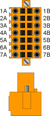
4.1 CN2 - USER PORT. RS232-RS422-RS485 (insulated)
The CN2 connector is present on both the device and the device R31FD30 C1-A1-HMI-QC104.
The connectors CN2 must be connected between them to achieve the connection between the operator interface and the control unit.
| CN2 | Terminal | RS232 | RS422 | RS485 | Description |
|---|---|---|---|---|---|
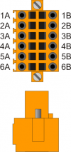 | 1A | - | - | A | Terminal A - RS485 |
| 2A | - | - | B | Terminal B - RS485 | |
| 3A | 0V | 0V | 0V | USER PORT common | |
| 4A | 0V | 0V | 0V USER PORT common | ||
| 5A | TX | - | - | Terminal TX - RS232 | |
| 6A | Terra | ||||
| 1B | - | RX | - | Terminal RX - RS422 | |
| 2B | - | RXN | - | Terminal RX N - RS422 | |
| 3B | - | TX | - | Terminal TX - RS422 | |
| 4B | - | TXN | - | Terminal TX N - RS422 | |
| 5B | RX | - | - | Terminal RX - RS232 | |
| 6B | Ground | ||||
Setup of USER PORT electric standard
In this application, the user should be set as port RS422 using the appropriate switch SW2 on both devices.
The connecting cable must follow the following schedule:
| Communication speed | 4800, 9600, 19200, 38400, 57600, 115200 baud |
|---|---|
| Communication mode | Full duplex |
| Operating mode | Differential |
| Max. number of devices connected on the line | 1 |
| Max. cable length | 1200 m |
| Input impedence | > 12 Kohm |
| Short-circuit current limit | 35 mA |


4.2 C1-R31-FG30.CN7 - 8 digital outputs static
| Connector | Pin | ID | Description | Address |
|---|---|---|---|---|
 | 1 | V+ | Outputs power supply (12÷28 Vdc) | |
| 2 | O1 | Enabling spindle | 3.OUT01 | |
| 3 | O2 | Activation by-pass safety barriers | 3.OUT02 | |
| 4 | - | n.c. | ||
| 5 | O3 | Turning oil pump for tilting bench | 3.OUT03 | |
| 6 | O4 | Enabling EV water cooling | 3.OUT04 | |
| 7 | 0V | 0V outputs power supply | ||
| 8 | O5 | Laser activation | 3.OUT05 | |
| 9 | O6 | Alarm in progress | 3.OUT06 | |
| 10 | O7 | Lamp presence alarm | 3.OUT07 | |
| 11 | O8 | Enabling EV climb bench | 3.OUT08 |
4.3 C1-R31-FG30.CN8 - 8 digital outputs static
| Connector | Pin | ID | Description | Address |
|---|---|---|---|---|
| | 1 | V+ | Outputs power supply (12÷28 Vdc) | |
| 2 | O9 | Enabling EV descent bench | 3.OUT09 | |
| 3 | O10 | Enable drive axis X | 3.OUT10 | |
| 4 | - | n.c. | ||
| 5 | O11 | Enable drive axis Y | 3.OUT11 | |
| 6 | O12 | Enable drive axis V | 3.OUT12 | |
| 7 | 0V | 0V outputs power supply | ||
| 8 | O13 | Enable drive axis Z | 3.OUT13 | |
| 9 | O14 | Enable drive axis C | 3.OUT14 | |
| 10 | O15 | Signaling axis in motion | 3.OUT15 | |
| 11 | O16 | Reset driver | 3.OUT16 |
4.4 C1-R31-FG30.CN9 - 8 digital outputs static
| Connector | Pin | ID | Description | Address |
|---|---|---|---|---|
| | 1 | V+ | Outputs power supply (12÷28 Vdc) | |
| 2 | O17 | Selection rotating disk (OFF) or cutter (ON) | 3.OUT17 | |
| 3 | O18 | Activation lubrication | 3.OUT18 | |
| 4 | - | n.c. | ||
| 5 | O19 | Riserva | 3.OUT19 | |
| 6 | O20 | Riserva | 3.OUT20 | |
| 7 | 0V | 0V outputs power supply | ||
| 8 | O21 | Riserva | 3.OUT21 | |
| 9 | O22 | Riserva | 3.OUT22 | |
| 10 | O23 | Riserva | 3.OUT23 | |
| 11 | O24 | Riserva | 3.OUT24 |
4.5 C1-R31-FG30.CN10 - 8 digital outputs static
All outputs to these terminals are marked as Reserve
4.6 A1-HMI-QC104.CN15 - 8 uscite digitali
| CN15 | Terminal | Symbol | Description |
|---|---|---|---|
 | 1 | V+ | Input for output power supply (12÷28Vdc) |
| 2 | O33 | Lamp automatic cycle stopped | |
| 3 | O34 | Lamp disk in motion with cycle stop | |
| 4 | N.C. | ||
| 5 | O35 | Lamp automatic cycle in progress | |
| 6 | O36 | Bypass safety barriers Active | |
| 7 | V- | Input for output power supply (12÷28Vdc) | |
| 8 | O37 | Lamp (or beep) alarm in progress | |
| 9 | O38 | Auxiliary lamp lit and ready CN | |
| 10 | O39 | reserve | |
| 11 | O40 | reserve |
4.7 C1-R31-FG30.CN11 - 8 "standard" inputs (PNP logic)
| Connector | Pin | ID | Description | Address | |
|---|---|---|---|---|---|
 | 1 | FI1 | PNP1) | reserve | FREQ1 |
| 2 | FI1 | NPN2) | |||
| 3 | 0V | Vout (0 V) - Digital inputs common I1÷I8 | |||
| 4 | I1 | FC Y Maximum | 3.INP01 | ||
| 5 | I2 | FC Y minimum | 3.INP02 | ||
| 6 | I3 | Motor driver disk fault | 3.INP03 | ||
| 7 | I4 | Disc motor running | 3.INP04 | ||
| 8 | I5 | Disc motor in stop | 3.INP05 | ||
| 9 | I6 | Auxiliary OK | 3.INP06 | ||
| 10 | I7 | Air disc motor and thermal OK | 3.INP07 | ||
| 11 | I8 | Thermal engine oil pump OK | 3.INP08 | ||
| 12 | - | n.c. | |||
4.8 C1-R31-FG30.CN12 - 8 "standard" inputs (PNP logic)
| Connector | Pin | ID | Description | Address | |
|---|---|---|---|---|---|
| | 1 | FI2 | PNP1) | reserve | FREQ2 |
| 2 | FI2 | NPN2) | |||
| 3 | 0V | Vout (0 V) - Digital inputs common I9÷I16 | |||
| 4 | I9 | Barrier closed | 3.INP09 | ||
| 5 | I10 | Pressure water present | 3.INP10 | ||
| 6 | I11 | Enabling tilting bench | 3.INP11 | ||
| 7 | I12 | Motor Driver X fault | 3.INP12 | ||
| 8 | I13 | Motor Driver Y fault | 3.INP13 | ||
| 9 | I14 | Motor Driver V fault | 3.INP14 | ||
| 10 | I15 | Motor Driver Z fault | 3.INP15 | ||
| 11 | I16 | Motor Driver C fault | 3.INP16 | ||
| 12 | - | n.c. | |||
4.9 C1-R31-FG30.CN13 - 8 "standard" inputs (PNP logic)
| Connector | Pin | ID | Description | Address | |
|---|---|---|---|---|---|
| | 1 | FI3 | PNP1) | reserve | FREQ3 |
| 2 | FI3 | NPN2) | |||
| 3 | 0V | Vout (0 V) - Digital inputs common I17÷I24 | |||
| 4 | I17 | FC X maximum | 3.INP17 | ||
| 5 | I18 | FC X minimum | 3.INP18 | ||
| 6 | I19 | FC Z maximum | 3.INP19 | ||
| 7 | I20 | FC Z minimum | 3.INP20 | ||
| 8 | I21 | FC C maximum | 3.INP21 | ||
| 9 | I22 | FC C minimum | 3.INP22 | ||
| 10 | I23 | Low oil level | 3.INP23 | ||
| 11 | I24 | reserve | 3.INP24 | ||
| 12 | - | n.c. | |||
4.10 C1-R31-FG30.CN14 - 8 "standard" inputs (PNP logic)
| Connector | Pin | ID | Description | Address | |
|---|---|---|---|---|---|
| | 1 | FI4 | PNP1) | reserve | FREQ4 |
| 2 | FI4 | NPN2) | |||
| 3 | 0V | Vout (0 V) - Digital inputs common I25÷I32 | |||
| 4 | I25 | reserve | 3.INP25 | ||
| 5 | I26 | reserve | 3.INP26 | ||
| 6 | I27 | reserve | 3.INP27 | ||
| 7 | I28 | reserve | 3.INP28 | ||
| 8 | I29 | reserve | 3.INP29 | ||
| 9 | I30 | reserve | 3.INP30 | ||
| 10 | I31 | Selector speed spindle blade | 3.INP31 | ||
| 11 | I32 | Selector tool spindle speed | 3.INP32 | ||
| 12 | - | n.c. | |||
4.11 A1-HMI-QC104.CN11 - 8 "standard" inputs (PNP logic)
| Connector | Pin | ID | Description | Address |
|---|---|---|---|---|
| | 1 | - | ||
| 2 | ||||
| 3 | 0V | Digital inputs common | ||
| 4 | I33 | RESET button automatic cycle | ||
| 5 | I34 | STOP automatic cycle (HOLD) | ||
| 6 | I35 | Jog button forward X | ||
| 7 | I36 | Button jog back X | ||
| 8 | I37 | Y jog button forward | ||
| 9 | I38 | Button jog back Y | ||
| 10 | - | Phase A Flyer | ||
| 11 | - | Phase B Flyer | ||
| 12 | 0V | Digital inputs and Flyer common |
4.12 A1-HMI-QC104.CN12 - 8 "standard" inputs (PNP logic)
| Connector | Pin | ID | Description | Address |
|---|---|---|---|---|
| | 1 | |||
| 2 | ||||
| 3 | 0V | Digital inputs common | ||
| 4 | I41 | Jog forward button Z | ||
| 5 | I42 | Jog back button Z | ||
| 6 | I43 | Button climb tilting bench | ||
| 7 | I44 | Button-down tilting bench | ||
| 8 | I45 | Start button | ||
| 9 | I46 | reserve | ||
| 10 | - | Phase A reserve | ||
| 11 | - | Phase B reserve | ||
| 12 | 0V | Digital inputs and Flyer common |
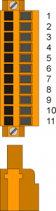
4.13 C1-R31-FG30.CN15 - 1 counter (PP, LD) - Axis X
| Connector | Pin | ID | Description | Address | ||
|---|---|---|---|---|---|---|
 | 1A | Internal bridge - 1A to 1B | ||||
| 2A | PHA1 | Phase A counter 1 | PNP Push-Pull 1) | 3.INP33 | 3.CNT01 | |
| 3A | PHB1 | Phase B counter 1 | 3.INP34 | |||
| 4A | Z1 | Z counter 1 | 1.INT01 | |||
| 5A | 0V | Common of counter inputs | ||||
| 6A | 0V | |||||
| 7A | 0V | |||||
| 1B | Internal bridge - 1A to 1B | |||||
| 2B | PHA1+ | + PHA counter 1 | Line Driver | 3.INP33 | 3.CNT01 | |
| 3B | PHB1+ | + PHB counter 1 | 3.INP34 | |||
| 4B | Z1+ | + Z counter 1 | 1.INT01 | |||
| 5B | PHAN1 | - PHA counter 1 | ||||
| 6B | PHBN1 | - PHB counter 1 | ||||
| 7B | ZN1 | - Z counter 1 | ||||
Configuration counter type PNP/Push-Pull:
- Terminal 5B = connect to terminal 5A
- Terminal 6B = connect to terminal 6A
- Terminal 7B = connect to terminal 7A
4.14 C1-R31-FG30.CN16 - 1 counter (PP, LD) - Axis Y
| Connector | Pin | ID | Description | Address | ||
|---|---|---|---|---|---|---|
| | 1A | Internal bridge - 1A to 1B | ||||
| 2A | PHA2 | Phase A counter 2 | PNP Push-Pull 1) | 3.INP35 | 3.CNT02 | |
| 3A | PHB2 | Phase B counter 2 | 3.INP36 | |||
| 4A | Z2 | Z counter 2 | 1.INT02 | |||
| 5A | 0V | Common of counter inputs | ||||
| 6A | 0V | |||||
| 7A | 0V | |||||
| 1B | Internal bridge - 1A to 1B | |||||
| 2B | PHA2+ | + PHA counter 2 | Line Driver | 3.INP35 | 3.CNT02 | |
| 3B | PHB2+ | + PHB counter 2 | 3.INP36 | |||
| 4B | Z2+ | + Z counter 2 | 1.INT02 | |||
| 5B | PHAN2 | - PHA counter 2 | ||||
| 6B | PHBN2 | - PHB counter 2 | ||||
| 7B | ZN2 | - Z counter 2 | ||||
Configuration counter type PNP/Push-Pull:
- Terminal 5B = connect to terminal 5A
- Terminal 6B = connect to terminal 6A
- Terminal 7B = connect to terminal 7A
4.15 C1-R31-FG30.CN17 - 1 counter (PP, LD) - Axis Z
| Connector | Pin | ID | Description | Address | ||
|---|---|---|---|---|---|---|
| | 1A | Internal bridge - 1A to 1B | ||||
| 2A | PHA3 | Phase A counter 3 | PNP Push-Pull 1) | 3.INP37 | 3.CNT03 | |
| 3A | PHB3 | Phase B counter 3 | 3.INP38 | |||
| 4A | Z2 | Z counter 3 | 1.INT03 | |||
| 5A | 0V | Common of counter inputs | ||||
| 6A | 0V | |||||
| 7A | 0V | |||||
| 1B | Internal bridge - 1A to 1B | |||||
| 2B | PHA3+ | + PHA counter 3 | Line Driver | 3.INP37 | 3.CNT03 | |
| 3B | PHB3+ | + PHB counter 3 | 3.INP38 | |||
| 4B | Z3+ | + Z counter 3 | 1.INT03 | |||
| 5B | PHAN3 | - PHA counter 3 | ||||
| 6B | PHBN3 | - PHB counter 3 | ||||
| 7B | ZN2 | - Z counter 3 | ||||
Configuration counter type PNP/Push-Pull:
- Terminal 5B = connect to terminal 5A
- Terminal 6B = connect to terminal 6A
- Terminal 7B = connect to terminal 7A
4.16 C1-R31-FG30.CN18 - 1 counter (PP, LD) - Axis V
| Connector | Pin | ID | Description | Address | ||
|---|---|---|---|---|---|---|
| | 1A | Internal bridge - 1A to 1B | ||||
| 2A | PHA3 | Phase A counter 4 | PNP Push-Pull 1) | 3.INP39 | 3.CNT04 | |
| 3A | PHB3 | Phase B counter 4 | 3.INP40 | |||
| 4A | Z2 | Z counter 4 | 1.INT04 | |||
| 5A | 0V | Common of counter inputs | ||||
| 6A | 0V | |||||
| 7A | 0V | |||||
| 1B | Internal bridge - 1A to 1B | |||||
| 2B | PHA3+ | + PHA counter 4 | Line Driver | 3.INP39 | 3.CNT04 | |
| 3B | PHB3+ | + PHB counter 4 | 3.INP40 | |||
| 4B | Z3+ | + Z counter 4 | 1.INT04 | |||
| 5B | PHAN3 | - PHA counter 4 | ||||
| 6B | PHBN3 | - PHB counter 4 | ||||
| 7B | ZN2 | - Z counter 4 | ||||
Configuration counter type PNP/Push-Pull:
- Terminal 5B = connect to terminal 5A
- Terminal 6B = connect to terminal 6A
- Terminal 7B = connect to terminal 7A
4.17 C1-R31-FG30.CN19 - 1 counter (PP, LD) - Axis C
| Connector | Pin | ID | Description | Address | ||
|---|---|---|---|---|---|---|
| | 1A | Internal bridge - 1A to 1B | ||||
| 2A | PHA3 | Phase A counter 5 | PNP Push-Pull 1) | 3.INP41 | 3.CNT05 | |
| 3A | PHB3 | Phase B counter 5 | 3.INP42 | |||
| 4A | Z2 | Z counter 5 | 1.INT05 | |||
| 5A | 0V | Common of counter inputs | ||||
| 6A | 0V | |||||
| 7A | 0V | |||||
| 1B | Internal bridge - 1A to 1B | |||||
| 2B | PHA3+ | + PHA counter 5 | Line Driver | 3.INP41 | 3.CNT05 | |
| 3B | PHB3+ | + PHB counter 5 | 3.INP42 | |||
| 4B | Z3+ | + Z counter 5 | 1.INT05 | |||
| 5B | PHAN3 | - PHA counter 5 | ||||
| 6B | PHBN3 | - PHB counter 5 | ||||
| 7B | ZN2 | - Z counter 5 | ||||
Configuration counter type PNP/Push-Pull:
- Terminal 5B = connect to terminal 5A
- Terminal 6B = connect to terminal 6A
- Terminal 7B = connect to terminal 7A
4.18 C1-R31-FG30.CN20 - 1 counter (PP, LD) - Axis A
| Connector | Pin | ID | Description | Address | ||
|---|---|---|---|---|---|---|
| | 1A | Internal bridge - 1A to 1B | ||||
| 2A | PHA3 | Phase A counter 6 | PNP Push-Pull 1) | 3.INP43 | 3.CNT06 | |
| 3A | PHB3 | Phase B counter 6 | 3.INP44 | |||
| 4A | Z2 | Z counter 6 | 1.INT06 | |||
| 5A | 0V | Common of counter inputs | ||||
| 6A | 0V | |||||
| 7A | 0V | |||||
| 1B | Internal bridge - 1A to 1B | |||||
| 2B | PHA3+ | + PHA counter 6 | Line Driver | 3.INP43 | 3.CNT06 | |
| 3B | PHB3+ | + PHB counter 6 | 3.INP44 | |||
| 4B | Z3+ | + Z counter 6 | 1.INT06 | |||
| 5B | PHAN3 | - PHA counter 6 | ||||
| 6B | PHBN3 | - PHB counter 6 | ||||
| 7B | ZN2 | - Z counter 6 | ||||
Configuration counter type PNP/Push-Pull:
- Terminal 5B = connect to terminal 5A
- Terminal 6B = connect to terminal 6A
- Terminal 7B = connect to terminal 7A
4.19 C1-R31-FG30.CN21, CN22 - 1 conteggio (PP, LD) - reserve
4.20 C1-R31-FG30.CN26 - 4 analog outputs
| Connector | Pin | ID | Description | Address |
|---|---|---|---|---|
 | 1 | GA01 | Common of analog outputs A01÷A02 | |
| 2 | AO1 | Axis X analog reference | 3.AN01 | |
| 3 | AO2 | Axis Y analog reference | 3.AN02 | |
| 4 | GA02 | ommon of analog outputs A03÷A04 | ||
| 5 | AO3 | Axis Z analog reference | 3.AN03 | |
| 6 | AO4 | Axis V analog reference | 3.AN04 |
4.21 C1-R31-FG30.CN27 - 4 analog outputs
| Connector | Pin | ID | Description | Address |
|---|---|---|---|---|
| | 1 | GA01 | Common of analog outputs A05÷A06 | |
| 2 | AO5 | Axis C analog reference | 3.AN05 | |
| 3 | AO6 | Reference (0-10V) for spindle speed | 3.AN06 | |
| 4 | n.c. | |||
| 5 | n.c. | |||
| 6 | n.c. | |||
4.22 C1-R31-FG30.CN28 - 2 analog inputs 12 bit (Potentiometer, 0-10V, 0-20mA)
| Connector | Terminal | Symbol | Description | Address |
|---|---|---|---|---|
 | 1 | GAI | Common of analog inputs | |
| 2 | IA01 | Setting cutting speed interpolation | 3.AI01 | |
| 3 | SEL1V | Volt mode analog input 0÷10V selector 11) | ||
| 4 | SEL1C | Ampere mode analog input 0÷20mA selector 12) | ||
| 5 | GAI | Common of analog inputs | ||
| 6 | IA02 | Amperage reading of the spindle motor | 3.AI02 | |
| 7 | SEL2V | Volt mode analog input 0÷10V selector 23) | ||
| 8 | SEL2C | Ampere mode analog input 0÷20mA selector 24) | ||
| 9 | VREF | Reference voltage |
4.23 C1-R31-FG30.CN29 - 2 analog inputs 12 bit (Potentiometer, 0-10V, 0-20mA)
All outputs of these terminals are marked as Reserve
4.24 A1-HMI-QC104.CN17 - 2 analog inputs 12 bit (Potentiometer, 0-10V, 0-20mA)
| Connector | Terminal | Symbol | Description |
|---|---|---|---|
| | 1 | GAI | Common of analog inputs |
| 2 | IA05 | Setting speed in the cutting direction | |
| 3 | SEL1V | Volt mode analog input 0÷10V selector 11) | |
| 4 | SEL1C | Ampere mode analog input 0÷20mA selector 12) | |
| 5 | GAI | Common of analog inputs | |
| 6 | IA06 | Setting speed in the opposite direction to the cutting | |
| 7 | SEL2V | Volt mode analog input 0÷10V selector 2 3) | |
| 8 | SEL2C | Ampere mode analog input 0÷20mA selector 2 4) | |
| 9 | VREF | Reference voltage |