AN001- Example of using and calibrating the CAMMING3 device
In this section we want to describe the first steps that will make the user in his first contact with the CAMMING device. Also you will describe some usage examples of the device.
We can divide in the following sections, the proceed of the operation:
-
device declaration in the configuration unit
-
introduction of parameters in order to correctly calibrate inputs and outputs
-
development of the application according to the needs
Device declaration in the configuration in unit
As was already explained in the description of the CAMMING device, you must program properly the unit application configuration. It is very important to the piece of code that declares the device, here you should indicate the hardware resources to be used to ensure proper operation. It will be the responsibility of the programmer to pick and choose the most appropriate inputs and outputs. For example with the following line of code:
;---------------------------------
; Internal devices declaration
;---------------------------------
INTDEVICE
device_name  CAMMING3  TCamp  CountS  CountMA  CountMB  IntL IAZero  IntLM IAZeroM InG     InGInt  IoutA  Out
Axis         CAMMING3  2      2.CNT01 2.CNT02  1.CNT01  1    2.INP01 2     2.INP02 2.INP03 5       2.AN01 2.OUT01
You define a CAMMING3 device with “Axis” name where the sampling time is 2 ms. The following are declared all hardware resources necessary for the use of the device, the detailed description is listed in the documentation for your device.
An application that has just inside the device Declaration in configuration unit and a qcl unit that it does not run anything (unless forced to WAIT) already allows to perform the first operations using the capabilities of the device. In fact after downloading the application tool and have done turn, will can change the parameters, observe the States or give commands to devices using the appropriate monitor from QView.
This is very convenient in the early stages of planning when you just want to make some runs or being debugged.
Correct device parameterization
Once declared hardware resources properly to use you need to set some parameters as components that are connected to the Qmove product.
Measure and pulse introduction
Consider the case where the transducer is a bi-directional digital encoder. Suppose that the encoder is directly keyed on an engine that should move the slave axis. You will need to set correctly the measure and pulse the parameters of the device so that it can interpret the pulses arriving at QMove, the instrument will then calculate the position of the axis. The measure and pulse introduction establishes a correspondence between a space in a unit of your choice and a certain number of pulses. In the event that the user already knows the space covered in a round encoder then you'll proceed directly to insert the values.
Example: If the encoder emits 1000 pulses/Rev and you know that the axis moves about 5 cm When the encoder performs exactly one lap then you can insert the following values:
AsseX:measure = 50;
AsseX:pulse = 4000
The measure value introduced involves choosing a unit of measure of mm for measuring positions, in the pulse parameter it was introduced a value equal to the number of encoder impulses multiplied by 4. It is remember that the measure/pulse relationship must be a value between 0.00935 and 1 (for compliance with the limits of accuracy of the device and the product QMove). It's important to remember that the values described above are taken as reference: it's not necessary to introduce the parameters with reference to an encoder revolution as we will describe below.
When the user does not know the measurement parameters, will still be able to make the correct calibration by following these steps:
-
give the INIT command to the device, verify that the st_init status switch to 1
-
through the “device monitor” of QView displayed on pc the parameter posit value
-
set measure and pulse both to the value 1
-
move the axis manually by having him make a move a position easily measurable
-
read the posit value
-
insert the desired measurement unit the measured value in the measure parameter and the value of the posit parameter in the pulse parameter.
The encoder resolution is now correctly set.
Another important step to take is to set the maxpos and minpos parameters that define respectively the maximum and the minimum position accessible from axis.
 | Nota: È necessario effettuare questa procedura due volte in modo da tarare correttamente sia l'asse master che l'asse slave |
|---|
Choice of the speed unit
The CAMMING device to measure the speed of the slave axis. The unit of measurement of the instantaneous speed of the axis is chosen through unitvel and decpt parameters. You can select the unit of time of speed with the unitvel parameter: if this is equal to 0 then the speed is measured in Um/min, If it is equal to 1 then is measured in Um/s. The decpt parameter instead determines whether multiple rate-measuring the fundamental unit of measure Um. For example, If the fundamental unit of measure is Um=mm, and unitvel=1 you get the speed indicator in the vel variable in:
mm/s (con decpt = 0),
cm/s (con decpt = 1),
dm/s (con decpt = 2),
m/s (con decpt = 3).
Later, if needed, you need to set the proper display on the terminal operator to adjust the correct decimal point position.
Analogue output calibration
 | Attention: before the placements you must make sure that wiring and mechanical parts are not cause malfunctions. |
|---|
We review the case where the CAMMING device uses an analogue output implemented with a DAC to control the slave axis: this will assume 16 bit resolution input discrete values (so between -32768 to 32767) to give analog voltage output range ±10V. This calibration function with analog output can be driven with a constant value in order to test links and functionality.
Preliminary motion
This section describes the steps to verify the correctness of the connections and the functionality of the system which was built.
-
give the INIT command to the device, verify that the st_init status switch to 1
-
give the RESUME command to remove a possible emergency condition (st_emrg = 1)
-
enable axis calibration status by running the CALON command, the st_cal state switch to 1
-
in these conditions you can set the analog voltage using the vout parameter: the value is expressed in tenths of a Volt (Therefore the range of values entered is ±100). It's recommended to introduce low values (5, 10, 15 …)
-
because now the device is used as “voltage generators” the axis should start moving. If this is not the case you should verify the correctness of the connections. When the axis is moving the frq parameter indicates the frequency of one of the input signals to the bi-directional counter, vel indicates the speed of the axis but posit the position according to the selected unit of measure. If giving positive voltage the position decreases, you must reverse the phases of transducer (or reversing the cables, or by using the CNTREV command) or reverse the direction of the drive
-
if with the output voltage of 0 V we note however that the axle is moving due to offset voltages, these can be offset using the offset parameter. For an optimal outcome of the calibration, the operation must be performed with the system temperature
-
now you can disable calibration status with the CALOFF command (the st_cal state switch to 0)
Analog output adjusting (maxvel parameter setting)
The EANPOS device raises the voltage value of the analogue output on the basis of a proportion between the maximum speed of the axis and the maximum output voltage. To do this you must set the maxvel parameter, that is the speed at which it moves the axle when you are given maximum voltage to the drive. Obviously the axle must behave symmetrical analog voltage to zero, therefore the speed must be the same (in module) to the maximum positive or negative voltage.
In order to know the maximum speed there are two ways: the “theoretical method” you must know the maximum motor speed (Max RPM declared) from which one can easily derive the linear velocity.
If you are not aware of the official maximum speed of the motor it is necessary to proceed in this way:
-
enter to the calibration mode (as described above)
-
if the system permits provide the maximum voltage to the drive and read the value of the vel parameter
-
you can also provide a lower voltage and calculate the maximum speed with the proportion vout : 10 V = vel : maxvel
Now you can then enter the value of the maximum speed in the maxvel parameter.
First moving
| Attention: before moving the axis, verify proper operation of emergency and protection devices. |
|---|
The procedures described here have allowed us to complete the first phase of parameterizing device. Now you can run smooth movement of the axis. For example, follow these steps:
-
give the INIT command to the device, verify that the st_init status switch to 1
-
move the axis in a position whereby we can take a particular space unobstructed position switches
-
set the tacc and tdec parameters
-
set the positioning speed with setvel parameter
-
set the positioning quota with setpos parameter
-
set the feedfw parameter to 1000 (100%)
-
reset any State of emergency with the RESUME command
-
start positioning with the START command, to stop the movement give the STOP command (or EMRG).
This first movement was done without turning the ring by reaction of space,so any error introduced by the values of offset voltage or by external agents does not correct.
Esempi di compilazione della cam table
Cam for wire-guide
For example, consider an application for spandifilo, the steps that you must follow the slave axis are:
-
starting with acceleration ramp
-
achieving a speed proportional to that of the master
-
maintaining the speed reached by a predetermined path
-
stop with deceleration ramp
-
stop for a certain space of the master
-
return to the starting point with the same outward stroke mode.
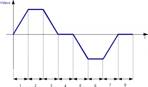
| Sector 1 | acceleration from zero speed and arrival at preset speed (codeG 131) with positive growth of the slave position; you need to correctly calculate the relationship between the master and slave output quotas because the speed is correct |
| Sector 2 | stretch at constant speed (codeG 133) with positive increase of the slave position |
| Sector 3 | deceleration with final speed 0 (codeG 135) with positive increase of the slave position |
| Sector 4 | stop slave axis (codeG 133): programming the master fee as you want while you leave anything that slave |
| Sector 5 | acceleration from zero speed and arrival at preset speed (codeG 131) with the slave position decrease; It is necessary to calculate correctly the relationship between master and slave quotas, because the output speed is correct (you can use the same values 1 sector with negative slave quota) |
| Sector 6 | stretch at constant speed (codeG 133) with the slave position decrease |
| Sector 7 | deceleration with final speed 0 (codeG 135) with the slave position decrease |
| Sector 8 | stop slave axis (codeG 133): programming the master quota as you want while you leave anything that slave quota |
After running 8 sector can perform functions that execute the re-phasing of master and slave positions in primary impulses by subtracting the space covered until the end of the sector; You can then re-execute the cam automatically.
Cam for fly-cutting with extra-speed
For example, consider an application for a simple flying cut, the steps that you must follow the slave axis are:
-
departure of the slave axis with acceleration ramp
-
reached of the master axis speed
-
maintaining the speed reached for the lifetime of the cutting operation
-
finished cutting the slave axis must accelerate to move at a higher speed and maintain it over a certain space
-
stopping the slave axis with deceleration ramp
-
return of the slave axis to the starting point executing acceleration and deceleration ramps.
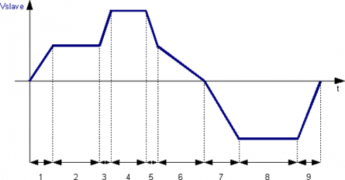
Sector 1: acceleration from zero speed and arrive at the same speed as the master (codeG 132) with positive growth of the slave position. Sector 2: intermediate section at constant speed (codeG 133) with positive increment of the slave position. Master and slave in this area will cover the same space. Sector 3: acceleration and positive increment of the slave axis position. The sector set is not accelerating (codeG 133), to make accelerate the slave will have to set a more space respect the master. Sector 4: stretch at constant speed and positive increment of the slave position (codeG 133). Sector 5: deceleration with positive increment of the slave position (codeG 133). It is reported the slave master speed, therefore the quota must be calculated correctly. Sector 6: deceleration with final speed 0 (codeG 135) with decrease in slave position. Sector 7: acceleration from zero speed and arriving at preset speed (codeG 131) with decrease in slave position. Sector 8: stretch at constant speed (codeG 133) with decrease in slave position. Sector 9: deceleration with final speed 0 (codeG 135) with decrease in slave position.
After running the sector 9 will execute the functions that execute the phasing adjustment of the master and slave position in primary pulses subtracting the space covered until the end of the sector; you can then re-execute the cam automatically.
Using a simulated master
As explained in the description of the CAMMING device It is possible that the master axis is real or simulated, one way to achieve a simulated master is to declare to the CAMMING device an address of a simulated transducer using a positioning device (for example EANPOS) declared with the counter on slot 1 (normally reserved to the CPU of the system) and any other resources that are disabled.
;---------------------------------
; Internal devices declaration
;---------------------------------
INTDEVICE
...
<device_name>        EANPOS  TCamp  ICont   IntL  IAZero  IOutA
Master               EANPOS  2      1.CNT01 X     X.X     X.X
The device thus configured as a simulated master, is operated like a normal device remember that the control loops must be open and therefore don't need to parameterize the PID, just set the feedforward to 100%.
Programming example
You want to use the EANPOS device configured in the example just described and there is suppose that the master simulated should continue its movement to infinity.
;------------------------------------------------------------
; Managing the master simulated
;------------------------------------------------------------
Master:measure = 1000         ;master parameters settings
Master:pulse = 4000
Master:decpt = 0
Master:unitvel = 1
Master:maxvel = 1000
Master:taccdec = 100
Master:maxpos = 999999
Master:minpos = -999999
INIT Master                   ;initialization simulated master
WAIT Master:st_init
LOOPOFF Master
WAIT NOT Master:st_loopon
RESUME Master
WAIT NOT Master:st_emrg

MAIN:
IF sf01                       ;flags that give the start to the master
  IF Master: st_still
    Master:posit = 0
    Master:setvel = 500
    Master:setpos = 999999
    START Master              ;START command
  ENDIF
  IF Master:posit GE 500000   ;I update the location so as not to cause
                              ;an overflow
    Master:posit = 0
  ENDIF
ELSE
  IF NOT Master:st_still      ;top of the simulated master
    STOP Master
  ENDIF
ENDIF

WAIT 1
JUMP MAIN
END