AN003 - Example of using and calibrating the COUNTER3 device
In this section we want to describe the first steps that will make the user in his first contact with the COUNTER3 device. You also want to provide a simple example using the COUNTER3 device.
We can divide in the following sections, the proceed of the operation:
-
device declaration in the configuration unit
-
introduction of parameters in order to correctly calibrate inputs and outputs
-
development of the application according to the needs
Device declaration in the unit configuration
As was already explained in the description of the COUNTER3 device, You must program properly the unit application configuration. It is very important to the part of code that declares the device, Here you should indicate the hardware resources to be used to ensure proper operation. It will be the responsibility of the programmer to pick and choose the most appropriate inputs and outputs. For example with the following line of code:
;---------------------------------
; Internal device declaration
;---------------------------------
INTDEVICE
...
Asse  COUNTER3  2  2.CNT02 3 2.OUT01 2.OUT02
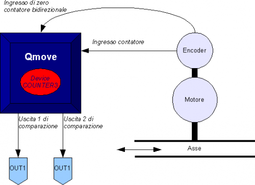
You define a COUNTER3 device with “Axis” name where the sampling time is 2 ms. Have been declared the following hardware resources: the input to the bidirectional counter has address 2.CNT02 (2 indicates the slot where installed the card, while CNT02 is the mnemonic name of the input), the number of digital input for interruption dedicated to the acquisition of the count (number 3) and finally the addresses of two exits used by comparators.
An application that has just inside the device declaration in the configuration unit and the qcl unit that it does not run anything (with the exception of the forced WAIT) already allows to perform the first operations using the capabilities of the device. In fact after downloading the application on the instrument and have done work, it can change the parameters, observe the States or give commands to devices using the appropriate monitor from QView.
This is very convenient in the early stages of planning when you just want to make some runs or being debugged.
Correct device parameterization
Once declared hardware resources properly to use you need to set some parameters as components that are connected to the product Qmove.
Introduction of measure and pulse
Let us consider the case that the bi-directional transducer is a digital encoder. Suppose that the encoder is directly keyed on an motor that is to move an axis. You will need to set the measure and pulse parameters of the device so that it can interpret the pulses arriving at QMove, the instrument will then calculate the position of the axis. The measure and pulse intrduction establishes a correspondence between a space in a unit of your choice and a certain number of pulses. In the event that the user already knows the space covered in a round encoder then you'll proceed directly to projecting values.
Let's clarify this concept with an example: If the encoder emits 1000 pulses/Rev and you know that the axis moves about 5 cm when the encoder covers exactly one revolution then you can enter the following values:
Axis:measure = 50;
Axis:pulse = 4000
The measure value introduced also involves choosing a unit of measure of mm for measuring positions, in the pulse parameter introduces a value equal to the number of encoder impulses multiplied by 4. It is remember that the measure/pulse relationship must be a value between 0.00935 to 1 (for compliance with the limits of accuracy of the device and the QMove product). It is important to emphasize that the values described above are taken as reference: It is not necessary to introduce the parameters with reference to an encoder revolution as we will describe below.
When the user does not know in advance the measurement parameters, will still be able to make the correct calibration by following these steps:
-
through the “device monitor” of QView displayed on pc the posit parameter value
-
set the measure and pulse both the value 1
-
move the axis manually by having him make a move a position easily measurable
-
read the posit value
-
now insert the desired measurement unit the measured value in the measure parameter and the value of the posit parameter in the pulse parameter.
The encoder resolution is now correctly set.
Development of an application
In the previous section, you learned what are the first steps to follow. This section contains a sample code, commented in detail, from which the user can get ideas to develop an application.
The way the device must be declared is explained above, and so this section is omitted configuration unit. See here
;*************************************************************************************
; Unit Qcl
;*************************************************************************************
;-------------------------------------------------------------------------------------
; Parameter adjustment of device operations
; ----------------------------- variables used --------------------------------
; slSet1: Comparison quota for output 2.OUT01
; slSet2: Comparison quota for output 2.OUT02
;-------------------------------------------------------------------------------------
Axis:measure = 1000
Axis:pulse = 1000           ;How to measure and calculate pulse is explained in special section*.
Axis:capture = 1            ;the instantaneous position of the axis is captured on the first face of
                            ;descent after activation of st_intenbl
IF slSet1 EQ 0
  slSet1 = 500
ENDIF
IF slSet2 EQ 0
  slSet2 = 100
ENDIF
;-------------------------------------------------------------------------------------
; Homing function enabled at each step the limit switch
; ---------------------------- variables used ---------------------------------
; slPrsPos : home position set
;--------------------------------------------------------------------------------------
MAIN:
  IF ifAbilZ                ;Waiting of zero pulse enable input transducer
    INTENBL Axis            ;Enables the capture of zero-pulse transducer
  ELSE
    INTDSBL Axis            ;Disable the capture of zero-pulse transducer
  ENDIF
  IF Axis:st_capture        ;If you have captured the instant position
    IF ifAxeFermo           ;If the axis is stopped
      Axis:delta = -(Axis:delta-slPrsPos) ;Dimension calculation from sum to count
      DELCNT Axis           ;Set on the new value of the reference count
      RSCAPTURE Axis        ;Reset the axis st_capture
    ENDIF
   ENDIF
;-------------------------------------------------------------------------------------
; Comparisons on the count only if ifAbilComp active, otherwise the outputs
; are disable
;-------------------------------------------------------------------------------------
  IF ifAbilComp
    IF NOT gfApp01
      Axis:mode1 = 5        ;Active out1 if posit>setpoint1
      Axis:selout1 = 0      ;and disable out1 if posit<setpoint1
      Axis:setpoint1 = slSet1 ;set of the setpoint dial gauge 1
      Axis:timer1 = 0       ;no delay in output switching
      Axis:mode2 = 6        ;Disable out2 if posit>setpoint2
      Axis:selout2 = 1      ;and active out2 if posit<setpoint2 comparator 2
      Axis:setpoint2 = slSet2 ;set of the setpoint
      Axis:timer2 = 0       ;no delay in output switching
      gfApp01 = 1
      gfApp02 = 0
      ENDIF
    ELSE
      IF NOT gfApp02
        Axis:mode1 = 0
        RESOUT out201       ;Disable out1
        Axis:selout1 = 0
        Axis:mode2 = 0
        RESOUT out202       ;Disable out2
        Axis:selout2 = 1
        gfApp01 = 0
        gfApp02 = 1
      ENDIF
    ENDIF
;-------------------------------------------------------------------------------------
; Final operations
;-------------------------------------------------------------------------------------
WAIT 1
JUMP MAIN
END
*how to colaculate the measure and pulse is explained in section special