| @cnna@ | Terminal | Symbol | Description | Address | ||
|---|---|---|---|---|---|---|
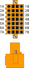  | 1A | Output + 24V dc1) | ||||
| 2A | PHA1 | Phase A | Count 1 PNP / Push-Pull2) | @slot@.INP17 | @slot@.CNT01 | |
| 3A | PHB1 | Phase B | @slot@.INP18 | |||
| 4A | Z1 | Z | 1.INT01 | |||
| 5A | 0V | Common for count inputs | ||||
| 6A | 0V | |||||
| 7A | 0V | |||||
| 1B | Output + 24V dc3) | |||||
| 2B | PHA1+ | + PHA | Count 1 Line Driver | @slot@.INP17 | @slot@.CNT01 | |
| 3B | PHB1+ | + PHB | @slot@.INP18 | |||
| 4B | Z1+ | + Z | 1.INT01 | |||
| 5B | PHA1- | - PHA | ||||
| 6B | PHB1- | - PHB | ||||
| 7B | Z1- | - Z | ||||
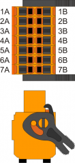
2)
PNP/Push-Pull type count input configuration:
Terminal 5B: connect to terminal 5A
Terminal 6B: connect to terminal 6A
Terminal 7B: connect to terminal 7A
Terminal 5B: connect to terminal 5A
Terminal 6B: connect to terminal 6A
Terminal 7B: connect to terminal 7A
| @cnnb@ | Terminal | Symbol | Description | Address | ||
|---|---|---|---|---|---|---|
| | 1A | Output + 24V dc1) | ||||
| 2A | PHA2 | Phase A | Count 2 PNP / Push-Pull2) | @slot@.INP19 | @slot@.CNT02 | |
| 3A | PHB2 | Phase B | @slot@.INP20 | |||
| 4A | Z2 | Z | 1.INT02 | |||
| 5A | 0V | Common for count inputs | ||||
| 6A | 0V | |||||
| 7A | 0V | |||||
| 1B | Output + 24V dc3) | |||||
| 2B | PHA2+ | + PHA | Count 2 Line Driver | @slot@.INP19 | @slot@.CNT02 | |
| 3B | PHB2+ | + PHB | @slot@.INP20 | |||
| 4B | Z2+ | + Z | 1.INT02 | |||
| 5B | PHA2- | - PHA | ||||
| 6B | PHB2- | - PHB | ||||
| 7B | Z2- | - Z | ||||
2)
PNP/Push-Pull type count input configuration:
Terminal 5B: connect to terminal 5A
Terminal 6B: connect to terminal 6A
Terminal 7B: connect to terminal 7A
Terminal 5B: connect to terminal 5A
Terminal 6B: connect to terminal 6A
Terminal 7B: connect to terminal 7A
| @cnnc@ | Terminal | Symbol | Description | Address | ||
|---|---|---|---|---|---|---|
| | 1A | Output + 24V dc1) | ||||
| 2A | PHA3 | Phase A | Count 3 PNP / Push-Pull2) | @slot@.INP21 | @slot@.CNT03 | |
| 3A | PHB3 | Phase B | @slot@.INP22 | |||
| 4A | Z3 | Z | 1.INT03 | FREQ13) | ||
| 5A | 0V | Common for count inputs | ||||
| 6A | 0V | |||||
| 7A | 0V | |||||
| 1B | Output + 24V dc4) | |||||
| 2B | PHA3+ | + PHA | Count 3 Line Driver | @slot@.INP21 | @slot@.CNT03 | |
| 3B | PHB3+ | + PHB | @slot@.INP22 | |||
| 4B | Z3+ | + Z | 1.INT03 | FREQ15) | ||
| 5B | PHA3- | - PHA | ||||
| 6B | PHB3- | - PHB | ||||
| 7B | Z3- | - Z | ||||
2)
PNP/Push-Pull type count input configuration:
Terminal 5B: connect to terminal 5A
Terminal 6B: connect to terminal 6A
Terminal 7B: connect to terminal 7A
Terminal 5B: connect to terminal 5A
Terminal 6B: connect to terminal 6A
Terminal 7B: connect to terminal 7A
| @cnnd@ | Terminal | Symbol | Description | Address | ||
|---|---|---|---|---|---|---|
| | 1A | Output + 24V dc1) | ||||
| 2A | PHA4 | Phase A | Count 4 PNP / Push-Pull2) | @slot@.INP23 | @slot@.CNT04 | |
| 3A | PHB4 | Phase B | @slot@.INP24 | |||
| 4A | Z4 | Z | 1.INT04 | FREQ23) | ||
| 5A | 0V | Common for count inputs | ||||
| 6A | 0V | |||||
| 7A | 0V | |||||
| 1B | Output + 24V dc4) | |||||
| 2B | PHA4+ | + PHA | Count 4 Line Driver | @slot@.INP23 | @slot@.CNT04 | |
| 3B | PHB4+ | + PHB | @slot@.INP24 | |||
| 4B | Z4+ | + Z | 1.INT04 | FREQ25) | ||
| 5B | PHA4- | - PHA | ||||
| 6B | PHB4- | - PHB | ||||
| 7B | Z4- | - Z | ||||
2)
PNP/Push-Pull type count input configuration:
Terminal 5B: connect to terminal 5A
Terminal 6B: connect to terminal 6A
Terminal 7B: connect to terminal 7A
Terminal 5B: connect to terminal 5A
Terminal 6B: connect to terminal 6A
Terminal 7B: connect to terminal 7A