DEVICE ANINP2
1. Introduction
-
The device manage the reading and processing of an analog input.
-
The read data is a word to signed 16-bit which you can add an offset, enter a scaling factor and activate a low-pass RC filter type software.
-
Input resolution specifications are listed in the file adapter of the card.
-
The outputs can be programmed to perform comparisons on analogue input
1.1 Installation
Device declaration in the configuration unit.
In the configuration unit, the BUS section must be declared so that they are
present the hardware resources required for the implementation of the ANINP2 device. Must be at least one analog input with 16-bit resolution.
In the INTDEVICE section of the configuration unit must be to add the following definition:
;---------------------------------
; Devices Declaration
;---------------------------------
INTDEVICE
...
<device name>   ANINP2   Tcamp   IChn   Type     Out1 Out2
where:
| <device name> | The name assigned to the device |
| ANINP2 | Keyword that identifies the device analog input |
| Tcamp | Time sampling device (1÷255 ms) |
| IChn | Address ADC input |
| Type | ID number input type (refer to technical data sheet hardware) |
| Out1 | 1 Output Address of comparison (to prevent the device uses this resource to put the X.X character) |
| Out2 | 2 Output Address of comparison (to prevent the device uses this resource to put the X.X character) |
1.2 Example
;---------------------------------
; Device declaration
;---------------------------------
INTDEVICE
Axis_X   ANINP2   2   2.AI01   1   2.OUT01   2.OUT02
1.3 Operation
When the system is powered, the device checks the correct input type declaration to use defined in configuration (Type) unit.
If the channel diagnostics ends successfully, data is upgraded on the basis of sampling time. If errors or inaccuracies are found, the
st_errcfg state is set to one and the value of the outbit variable is forced to zero.
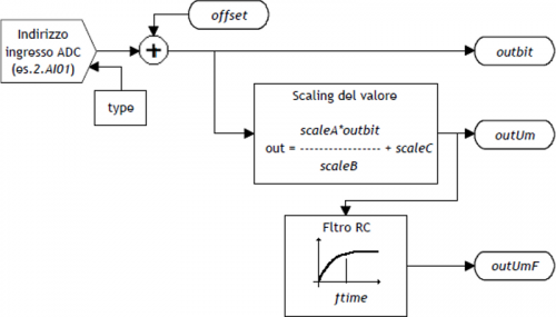
The conversion of the data output from the (outbit) device, in the unit of measure required by your application,
is performed using scale factors (scaleA, scaleB e scaleC) according to the formula:
outUm = (scaleA x outbit / scaleB) + scaleC
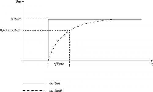
In addition to this updated release based on the sample time of the device, is available the outUmF output, filtered using a programmable charge time (in ms).
 | This feature allows you to filter any interferences and fluctuations superimposed to the wanted signal, with the ability to customize the charging time of the filter (tfilter). |
|---|
1.3.1 Outputs management
The device he can handle analog input mediated comparisons (outUmF)
and change the status of the programmable outputs in one shot mode (single activation).
Each output can be handled in the following ways:
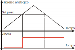 | Activating setpoint is exceeded by the input that increases |
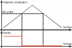 | Disable setpoint is exceeded by the input that increases |
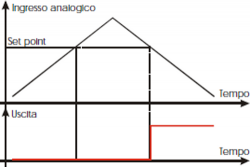 | Activating setpoint is exceeded by the input which decrements |
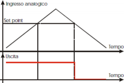 | Disable setpoint is exceeded by the input which decrements |
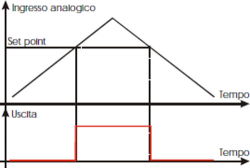 | Activating setpoint is exceeded by the input that is incremented and disable setpoint is exceeded by the input which decrements |
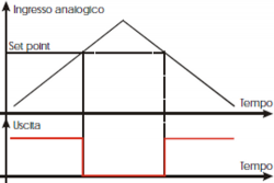 | Disable setpoint is exceeded by the input that is incremented and activating setpoint is exceeded by the input which decrements |
1.3.2 Hysteresis
The device can manage the output comparisons with interests.
Whenever the device varies the State of an output, the input is disabled until the comparison does not deviate from the setpoint hysteresis value.
Specifically the comparison is rearm when the entrance takes on the values listed in the examples following:
| Mode = 1 | outUmF = setpoint - hysteresis |
| Mode = 2 | outUmF = setpoint - hysteresis |
| Mode = 3 | outUmF = setpoint + hysteresis |
| Mode = 4 | outUmF = setpoint + hysteresis |
If you are using the 5 snd 6 modes, the output will behave as follows:
| Activation | Deactivation | |
| Mode = 5 | outUmF = setpoint | outUmF = setpoint - hysteresis |
| Mode = 6 | outUmF = setpoint - hysteresis | outUmF = setpoint |
1.4 Device Error Management
A bug in the device is signaled by the st_error state.
When st_error is equal to 1, we find the errcode variable for the error type
(see the table) and the errvalue variable for the indication on the cause of the error
| Code | Priority | Description |
|---|---|---|
| - | - | - |
If the device goes in error, in order to start the work you must to clear the st_error status through the RSERR command.
1.5 Warning Device Management
A warning in the camming system is reported by the st_warning state.
Being caused by a minor event and being guaranteed in this situation, the management of the slave axis, the slave axis continues his work.
When st_warning variable is 1, are present on the wrncode variable the warning type
(see the table) and in the wrnvalue variable an indication as to the cause that produced the warning.
| Code | Priority | Description |
|---|---|---|
| 1 | 0 | Command not executed |
To clear the st_warning status must send the RSWRN command.
1.6 Commands and parameters table
1.6.1 Symbols used
The name of the paramenter, state or command are carry to the left side of the table.
R
Indicates if the related parameter or stare is ritentive (upon initialization of the device maintains the previously defined), or is the State that bears upon initialization of the device.
If the device does not need to initialize the 'R' field indicates the value that the parameter assume on the turning on the card.
R = Ritentive
0 = At the initialization moment of the device the value is forced to zero.
1 = At the initialization moment of the device the value is forced to one.
- = At the initialization moment of the device significant value is displayed.
D
Indicates the size of the parameter.
F = Flag
B = Byte
W = Word
L = Long
S = Single Float
1.6.1.1 Conditions
Describes all of the conditions that is considered correct or because the command is accepted.
In some cases, limit values are specified for the acceptance of the parameter: If any values outside the limits set, the data will still be accepted; therefore appropriate controls of the application must be provided to ensure proper operation.
To run a command, all the conditions required to be met; otherwise the command does not run.
A
Indicates the access mode.
R = Read (read).
W = Write (write).
RW = Read / Write.
1.6.2 Parameters
| Name | D | R | A | Conditions | Description |
|---|---|---|---|---|---|
| outbit | W | - | R | None | Output measure in bits Value read by the input channel offset even. Valid Range: 0 ÷ 32767 |
| offset | W | R | RW | None | Offset compensation DAC output offset in bit. Defines the value in bits of the correction on the analog input in order to compensate for any drift in the system. Valid Range: -32768 ÷ 32767 |
| scaleA | W | R | RW | None | A Scale\\A integer parameter scaling formula. Valid Range: -32768 ÷ 32767 |
| scaleB | W | R | RW | None | B Scale\\B parameter value used in the scaling formula. Must be nonzero. Valid Range: -32768 ÷ 32767 |
| scaleC | W | R | RW | None | C Scale\\C parameter value used in the scaling formula. Valid Range: -32768 ÷ 32767 |
| outUm | L | - | R | None | Output measure in unity Derived exit from scaling formula. Valid Range: -32768 ÷ 32767 |
| tfilter | W | R | RW | None | Filter time Charging time of RC filter. If tfilter < = Tcamp device, the filter is disable. Value expressed in ms. Valid Range: 0 ÷ 32767 |
| outUmF | L | - | R | None | Filtered output in unity of measure Output in units, filtered. Valid Range: -32768 ÷ 32767 |
| hysteresis | L | R | RW | None | Comparation hysteresis Hysteresis of comparisons for outputs managing. See the dedicated chapter. Valid Range: -32768 ÷ 32767 |
| mode1 | B | R | R-W | None | Function mode 1 Defines the comparison type to be performed on the output shown in the selout1 parameter. 0 = The output remains in the state it is 1 = Passage activation to the setpoint to the input that increase 2 = Passage deactivation to the setpoint with the count that increases 3 = Passage activation for the setpoint with the input that it decrements 4 = Passage disabling for the setpoint with the input that it decrements 5 = Passage activation for the setpoint with the input that is incremented and passage deactivating with the setpoint to the input that it decrements 6 = Passage disabling for the setpoint with the input that is incremented and passage activation with the setpoint to the input that it decrements Valid Range: 0 ÷ 6. |
| selout1 | B | R | R-W | None | Output selection1 Indicates the first output where the action of the first comparison 0 = Out1 1 = Out2 Valid Range: 0 ÷ 1. |
| setpoint1 | L | R | R-W | None | Set point 1 Defines the set point of comparison to be performed on the output shown in the parameter selout1. Valild Range: -999999 ÷ 999999. |
| timer1 | W | R | R-W | None | Timer 1 Defines the timer to be running on the output shown in the parameter selout1. Valid Range: 0 ÷ 32767. |
| mode2 | B | R | R-W | None | Function mode 2 Defines the comparison type to be performed on the output shown in the selout2 parameter. 0 = The output remains in the State where is 1 = Passage activation for the setpoint to the input that you increase 2 = Passage deactivation in step for the setpoint to the input that you increase 3 = Passage activation for the setpoint to the input that it decrements 4 = Passage disabling for the setpoint with the admission that it decrements 5 = Passage activation for the setpoint with the input that is incremented and passage deactivating for the setpoint with the input that it decrements 6 = Passage disabling for the setpoint with the input that is incremented and passage activation for the setpoint with counting that decrements Valid Range: 0 ÷ 6. |
| selout2 | B | R | R-W | None | Output selection2 Indicates the output where the action runs the second comparison 0 = Out1 1 = Out2 Valid Range: 0 ÷ 1. |
| setpoint2 | L | R | R-W | None | Set point 2 Defines the set point comparison to be performed on the output shown in the selout2 parameter. Valid Range: -999999 ÷ 999999. |
| timer2 | W | R | R-W | None | Timer 2 Defines the timer to be running on the output shown in the selout2 parameter. Valid Range: 0 ÷ 32767. |
1.6.3 States
| NAME | D | R | A | Conditions | Description |
|---|---|---|---|---|---|
| st_errcfg | F | - | R | None | Configuration error Signals that an error was detected in the input configuration. 0 = There was no error. 1 = An error was detected. |
| st_cmp1 | F | 0 | R | None | Status of first comparation 1 comparison report. 0 = 1 disable comparison. 1 = 1 active comparison. At the power on by default is set to zero. |
| st_cmp2 | F | 0 | R | None | Status of second comparation 2 comparison report. 0 = 2 disable comparison. 1 = 2 active comparison. At the power on by default is set to zero. |
| st_error | F | 0 | R | None | Status of device error Indicates the error status in device. To decode the error you must refer to the errcode and errvalue variables. 0 = Error not present. 1 = Error present. At the power on by default is set to zero. |
| st_warning | F | 0 | R | None | Status of device warning Indicates the warning state in device. To decode the error you must refer to the wrncode and wrnvalue variables. 0 = Warning not present. 1 = Warning present. At the power on by default is set to zero. |
1.6.4 Commands
Controls were organized by decreasing priority. For example, in the case of contemporary SETCMP1 and RESCMP1 controls, is acquired first SETCMP1 command.
| Name | Description | Description |
|---|---|---|
| SETCMP1 | None | Set of comparation 1 Activates the st_cmp1 status. |
| RESCMP1 | None | Reset of comparation 1 Reset the st_cmp1 status. |
| SETCMP2 | None | Set of comparation 2 Activates the st_cmp2 status. |
| RESCMP2 | None | Reset of comparation 2 Reset the st_cmp2 status. |
| RSERR | None | Reset error Reset the st_error status. |
| RSWRN | None | Reset warning Reset the st_warning status. |
1.7 Limitations
1.7.1 Scaling
ScaleB must be set to non-zero, otherwise OutUm is forced to 0.
1.7.2 Filter
The charging time of RC element tfilter must be set greater than or equal to the time of sampling device (Tcamp), otherwise it disables the filter and the OutUmF parameter refreshes that has the same value as OutUm.
1.7.3 Offset
The offset parameter is added to the analog input acquired (outbit), don't execute the control over the overflow of the sum.
1.7.4 Configuration
| In the case that a single channel is managed by multiple ANINP device with Type differents, the compiler does not detect errors and the channel is set with the last Type declared. |
|---|
A single hardware resource (each input) can be handled by multiple ANINP devices simultaneously, provided that the identification number of the input (Type), contained in the Declaration of the device (configuration file), is the same; otherwise the analog input is configured as the last device declared in the configuration file.
1.8 Application example
1.8.1 Configuration Unit
;*************************************************************************************
; Module Name: Ex_Aninp2.CNF                Project: Ex_ANINP2
; Author: QEM srl                           Date : 01/05/99
; Siystem: QMove1 / QCL3                    Library: 1LIB4001
; Functionality: ANINP2 use management      Release: 0
;------------------------------------- Note ------------------------------------------
; [1] - Application example using device ANINP2
;*************************************************************************************

;-------------------------------------------------------------------------------------
; Constants Defining
;-------------------------------------------------------------------------------------
CONST

;-------------------------------------------------------------------------------------
; SYSTEM Variable Definition
;-------------------------------------------------------------------------------------
SYSTEM
slSet1   L                                      ;Setpoint 1
slSet2   L                                      ;Setpoint 2

;-------------------------------------------------------------------------------------
; GLOBAL Variable Definition
;-------------------------------------------------------------------------------------
GLOBAL

;-------------------------------------------------------------------------------------
; TIMER Variable Definition
;-------------------------------------------------------------------------------------
TIMER

;-------------------------------------------------------------------------------------
; DATAGROUP Definition
;-------------------------------------------------------------------------------------
DATAGROUP

;-------------------------------------------------------------------------------------
; Bus Configuration
;-------------------------------------------------------------------------------------
BUS
   1  1CPUD   01
   2  1AI8B   00
   3  1MIXA   00
   4  .

;-------------------------------------------------------------------------------------
; INPUT Variable Definition
;-------------------------------------------------------------------------------------
INPUT
ifAbilComp   F     3.INP01                      ;Enabling comparisons

;-------------------------------------------------------------------------------------
; OUTPUT Variable Definition
;-------------------------------------------------------------------------------------
OUTPUT
out301       F     3.OUT01                      ;1 setpoint signal
out302       F     3.OUT02                      ;2 setpoint signal

;-------------------------------------------------------------------------------------
; Internal devices declaration
;-------------------------------------------------------------------------------------
INTDEVICE
;Name    Type    TCamp    Counter Type
Axis     ANINP   0004     2.AI01 2  3.OUT01  3.OUT02

END
1.8.2 ANINP2 management
;*************************************************************************************
; File name: TASK_00.MOD
; Project: EX_ANINP2
; Description: Positioning Control
;*************************************************************************************

;-------------------------------------------------------------------------------------
; Initialization work Axis
;-------------------------------------------------------------------------------------
Axis:offset = 0                                 ;Offset voltage

;-------------------------------------------------------------------------------------
; Scale factor: (scaleA * outbit / scaleB) + scaleC
; outUm min = (4 * 0 / 8 ) + 3 = 3
; outUm max = (4 * 4095 / 8) + 3 = 2050
;-------------------------------------------------------------------------------------
Axis: scaleA = 4                                ;A scale factor
Axis: scaleB = 8                                ;B scale factor
Axis: scaleC = 3                                ;C scale factor
Axis: tfilter = 10                              ;Capture filter time
Axis: hysteresis = 0                            ;Output hysteresis

IF   slSet1 EQ 0
 sl   Set1 = 1500
ENDIF
IF   slSet2 EQ 0
 sl   Set2 = 300
ENDIF

MAIN:
;-------------------------------------------------------------------------------------
; Comparisons on the count only if ifAbilComp is active, otherwise the outputs
; are inactive
; ----------------------------- used variables --------------------------------
; slSet1: Comparison quota for 2.OUT01 output
; slSet1: Comparison quota for 2.OUT02 output
;-------------------------------------------------------------------------------------

IF ifAbilComp
     IF NOT gfApp01
       Axis: mode1 = 5                         ;Activates out1 if posit > setpoint1
       Axis: selout1 = 0                       ;and disable out1 if posit < setpoint1
       Axis: setpoint1 = slSet1
       Axis: timer1 = 0
       Axis: mode2 = 6                         ;Disable out2 if posit < setpoint2
       Axis: selout2 = 1                       ;and disable out2 if posit < setpoint2
       Axis: setpoint2 = slSet2
       Axis: timer2 = 0
       gfApp01 = 1
       gfApp02 = 0
     ENDIF
ELSE
     IF NOT gfApp02
       Axis:mode1 = 0
       RESOUT out201                           ;Disable out1
       Axis: selout1 = 0
       Axis: mode2 = 0
       RESOUT out202                           ;Disable out2
       Axis: selout2 = 1
       gfApp01 = 0
       gfApp02 = 1
     ENDIF
ENDIF

;-------------------------------------------------------------------------------------
; Final operations
;-------------------------------------------------------------------------------------
  WAIT 1
  JUMP MAIN
END