This is an old revision of the document!
DEVICE ANINP2
0.1 Introduction
-
The device manage the reading and processing of an analog input.
-
The read data is a word to signed 16-bit which you can add an offset, enter a scaling factor and activate a low-pass RC filter type software.
-
Input resolution specifications are listed in the file adapter of the card.
-
The outputs can be programmed to perform comparisons on analogue input
0.2 Installation
Device declaration in the configuration unit.
In the configuration unit, the BUS section must be declared so that they are
present the hardware resources required for the implementation of the ANINP2 device. Must be at least one analog input with 16-bit resolution.
In the INTDEVICE section of the configuration unit must be to add the following definition:
;---------------------------------
; Devices Declaration
;---------------------------------
INTDEVICE
...
<device name>   ANINP2   Tcamp   IChn   Type     Out1 Out2
where:
| <device name> | The name assigned to the device |
| ANINP2 | Keyword that identifies the device analog input |
| Tcamp | Time sampling device (1÷255 ms) |
| IChn | Address ADC input |
| Type | ID number input type (refer to technical data sheet hardware) |
| Out1 | 1 Output Address of comparison (to prevent the device uses this resource to put the X.X character) |
| Out2 | 2 Output Address of comparison (to prevent the device uses this resource to put the X.X character) |
0.3 Example
;---------------------------------
; Device declaration
;---------------------------------
INTDEVICE
Axis_X   ANINP2   2   2.AI01   1   2.OUT01   2.OUT02
0.4 Operation
When the system is powered, the device checks the correct input type declaration to use defined in configuration (Type) unit.
If the channel diagnostics ends successfully, data is upgraded on the basis of sampling time. If errors or inaccuracies are found, the
st_errcfg state is set to one and the value of the outbit variable is forced to zero.
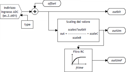
The conversion of the data output from the (outbit) device, in the unit of measure required by your application,
is performed using scale factors (scaleA, scaleB e scaleC) according to the formula:
outUm = (scaleA x outbit / scaleB) + scaleC
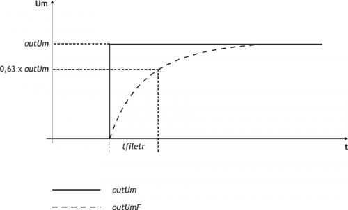
In addition to this updated release based on the sample time of the device, is available the outUmF output, filtered using a programmable charge time (in ms).
 | This feature allows you to filter any interferences and fluctuations superimposed to the wanted signal, with the ability to customize the charging time of the filter (tfilter). |
|---|
0.4.1 Outputs management
The device he can handle analog input mediated comparisons (outUmF)
and change the status of the programmable outputs in one shot mode (single activation).
Each output can be handled in the following ways:
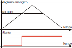 | Activating setpoint is exceeded by the input that increases |
 | Disable setpoint is exceeded by the input that increases |
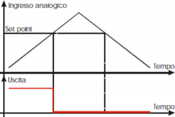
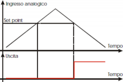 | Activating setpoint is exceeded by the input which decrements |
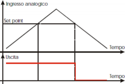 | Disable setpoint is exceeded by the input which decrements |
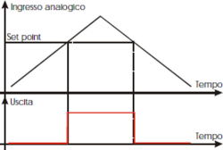 | Activating setpoint is exceeded by the input that is incremented and disable setpoint is exceeded by the input which decrements |
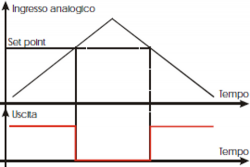 | Disable setpoint is exceeded by the input that is incremented and activating setpoint is exceeded by the input which decrements |
0.4.2 Hysteresis
The device can manage the output comparisons with interests.
Whenever the device varies the State of an output, the input is disabled until the comparison does not deviate from the setpoint hysteresis value.
Specifically the comparison is rearm when the entrance takes on the values listed in the examples following:
| Mode = 1 | outUmF = setpoint - hysteresis |
| Mode = 2 | outUmF = setpoint - hysteresis |
| Mode = 3 | outUmF = setpoint + hysteresis |
| Mode = 4 | outUmF = setpoint + hysteresis |
If you are using the 5 snd 6 modes, the output will behave as follows:
| Activation | Deactivation | |
| Mode = 5 | outUmF = setpoint | outUmF = setpoint - hysteresis |
| Mode = 6 | outUmF = setpoint - hysteresis | outUmF = setpoint |
0.5 Device Error Management
A bug in the device is signaled by the st_error state.
When st_error is equal to 1, we find the errcode variable for the error type
(see the table) and the errvalue variable for the indication on the cause of the error
| Code | Priority | Description |
|---|---|---|
| - | - | - |
If the device goes in error, in order to start the work you must to clear the st_error status through the RSERR command.
0.6 Warning Device Management
A warning in the camming system is reported by the st_warning state.
Being caused by a minor event and being guaranteed in this situation, the management of the slave axis, the slave axis continues his work.
When st_warning variable is 1, are present on the wrncode variable the warning type
(see the table) and in the wrnvalue variable an indication as to the cause that produced the warning.
| Code | Priority | Description |
|---|---|---|
| 1 | 0 | Command not executed |
To clear the st_warning status must send the RSWRN command.
0.7 Commands and parameters table
0.7.1 Symbols used
The name of the paramenter, state or command are carry to the left side of the table.
R
Indicates if the related parameter or stare is ritentive (upon initialization of the device maintains the previously defined), or is the State that bears upon initialization of the device.
If the device does not need to initialize the 'R' field indicates the value that the parameter assume on the turning on the card.
R = Ritentive
0 = At the initialization moment of the device the value is forced to zero.
1 = At the initialization moment of the device the value is forced to one.
- = At the initialization moment of the device significant value is displayed.
D
Indicates the size of the parameter.
F = Flag
B = Byte
W = Word
L = Long
S = Single Float
0.7.1.1 Condizioni
Vengono descritte tutte le condizioni necessarie affinché il parametro sia considerato corretto o perché il comando venga accettato.
In alcuni casi vengono specificati dei valori limite per laccettazione del parametro: se vengono introdotti dei valori esterni ai limiti impostati, il dato viene comunque accettato; pertanto devono essere previsti opportuni controlli dellapplicativo tali da garantire il corretto funzionamento.
Per lesecuzione di un comando, tutte le relative condizioni devono necessariamente essere soddisfatte; in caso contrario il comando non viene eseguito.
A
Indica la modalità di accesso.
R = Read (lettura).
W = Write (scrittura).
RW = Read / Write.
0.7.2 Parametri
| Nome | D | R | A | Condizioni | Descrizione |
|---|---|---|---|---|---|
| outbit | W | - | R | Nessuna | Output measure in bits Valore letto dal canale di ingresso compensato dell'Offset. Range valido: 0 ÷ 32767 |
| offset | W | R | RW | Nessuna | Offset compensation Offset uscita DAC in bit. Definisce il valore in bit della correzione relativa all'ingresso analogico in modo da compensare l'eventuale deriva del sistema. Range valido: -32768 ÷ 32767 |
| scaleA | W | R | RW | Nessuna | Scale A Valore intero parametro A formula di scaling. Range valido: -32768 ÷ 32767 |
| scaleB | W | R | RW | Nessuna | Scale B Valore parametro B utilizzato nella formula di scaling. Deve essere necessariamente diverso da zero. Range valido: -32768 ÷ 32767 |
| scaleC | W | R | RW | Nessuna | Scale C\\Valore parametro C utilizzzato nella formula di scaling. Range valido: -32768 ÷ 32767 |
| outUm | L | - | R | Nessuna | Output measure in unity Uscita derivata dalla formula di scaling. Range valido: -32768 ÷ 32767 |
| tfilter | W | R | RW | Nessuna | Filter time Tempo di carica del filtro RC. Se tfilter < = Tcamp device, il filtro è disattivato. Valore espresso in unità ms. Range valido: 0 ÷ 32767 |
| outUmF | L | - | R | Nessuna | Filtered output in unity of measure Uscita in unità di misura, filtrata. Range valido: -32768 ÷ 32767 |
| hysteresis | L | R | RW | Nessuna | Comparation hysteresis Isteresi delle comparazioni per la gestione delle uscite. Vedi capitolo dedicato. Range valido: -32768 ÷ 32767 |
| mode1 | B | R | R-W | Nessuna | Function mode 1 Definisce il tipo di comparazione da eseguire sull'uscita indicata nel parametro selout1. 0 = L'uscita permane nello stato in cui si trova 1 = Attivazione al passaggio per il setpoint con l'ingresso che si incrementa 2 = Disattivazione al passaggio per il setpoint con il conteggio che si incrementa 3 = Attivazione al passaggio per il setpoint con l'ingresso che si decrementa 4 = Disattivazione passaggio per il setpoint con l'ingresso che si decrementa 5 = Attivazione passaggio per il setpoint con l'ingresso che si incrementa e disattivazione passaggio per il setpoint con l'ingresso che si decrementa 6 = Disattivazione passaggio per il setpoint con l'ingresso che si incrementa e attivazione al passaggio per il setpoint con l'ingresso che si decrementa Range valido: 0 ÷ 6. |
| selout1 | B | R | R-W | Nessuna | Output selection1 Indica su quale uscita viene eseguita l'azione della prima comparazione 0 = Out1 1 = Out2 Range valido: 0 ÷ 1. |
| setpoint1 | L | R | R-W | Nessuna | Set point 1 Definisce il setpoint della comparazione da eseguire sull'uscita indicata nel parametro selout1. Range valido: -999999 ÷ 999999. |
| timer1 | W | R | R-W | Nessuna | Timer 1 Definisce il timer da porre in esecuzione sull'uscita indicata nel parametro selout1. Range valido: 0 ÷ 32767. |
| mode2 | B | R | R-W | Nessuna | Function mode 2 Definisce il tipo di comparazione da eseguire sull'uscita indicata nel parametro selout2. 0 = L'uscita permane nello stato in cui si trova 1 = Attivazione al passaggio per il setpoint con l'ingresso che si incrementa 2 = Disattivazione al passaggio per il setpoint con l'ingresso che si incrementa 3 = Attivazione al passaggio per il setpoint con l'ingresso che si decrementa 4 = Disattivazione passaggio per il setpoint con l'ingresso che si decrementa 5 = Attivazione passaggio per il setpoint con l'ingresso che si incrementa e disattivazione passaggio per il setpoint con l'ingresso che si decrementa 6 = Disattivazione passaggio per il setpoint con l'ingresso che si incrementa e attivazione al passaggio per il setpoint con il conteggio che si decrementa Range valido: 0 ÷ 6. |
| selout2 | B | R | R-W | Nessuna | Output selection2 Indica su quale uscita viene eseguita l'azione della seconda comparazione 0 = Out1 1 = Out2 Range valido: 0 ÷ 1. |
| setpoint2 | L | R | R-W | Nessuna | Set point 2 Definisce il setpoint della comparazione da eseguire sull'uscita indicata nel parametro selout2. Range valido: -999999 ÷ 999999. |
| timer2 | W | R | R-W | Nessuna | Timer 2 Definisce il timer da porre in esecuzione sull'uscita indicata nel parametro selout2. Range valido: 0 ÷ 32767. |
0.7.3 Stati
| NOME | D | R | A | Condizioni | Descrizione |
|---|---|---|---|---|---|
| st_errcfg | F | - | R | Nessuna | Configuration error Segnala che è stato rilevato un errore nella configurazione dell'ingresso. 0 = Non è stato rilevato nessun errore. 1 = È stato rilevato un errore. |
| st_cmp1 | F | 0 | R | Nessuna | Status of first comparation Segnalazione di comparazione 1. 0 = Comparazione 1 disattiva. 1 = Comparazione 1 attiva. All'accensione per default viene posto a zero. |
| st_cmp2 | F | 0 | R | Nessuna | Status of second comparation Segnalazione di comparazione 2. 0 = Comparazione 2 disattiva. 1 = Comparazione 2 attiva. All'accensione per default viene posto a zero. |
| st_error | F | 0 | R | Nessuna | Status of device error Indica lo stato di errore nel device. Per la decodifica dell'errore si deve fare riferimento alla variabile errcode ed errvalue. 0 = Errore non presente. 1 = Errore presente. All'accensione per default viene posto a zero. |
| st_warning | F | 0 | R | Nessuna | Status of device warnin Indica lo stato di warning nel device. Per la decodifica del warning si deve fare riferimento alla variabile wrncode e wrnvalue. 0 = Warning non presente. 1 = Warning presente All'accensione per default viene posto a zero. |
0.7.4 Comandi
I comandi sono stati ordinati con priorità decrescente. Ad esempio, in caso di contemporaneità dei comandi SETCMP1 ed RESCMP1, viene acquisito per primo il comando SETCMP1.
| Nome | Descrizione | Descrizione |
|---|---|---|
| SETCMP1 | Nessuna | Set of comparation 1 Attiva lo stato st_cmp1. |
| RESCMP1 | Nessuna | Reset of comparation 1 Azzera lo stato st_cmp1. |
| SETCMP2 | Nessuna | Set of comparation 2 Attiva lo stato st_cmp2. |
| RESCMP2 | Nessuna | Reset of comparation 2 Azzera lo stato st_cmp2. |
| RSERR | Nessuna | Reset error Azzera lo stato st_error. |
| RSWRN | Nessuna | Reset warning Azzera lo stato st_warning. |
0.8 Limitazioni
0.8.1 Scaling
ScaleB deve essere impostato diverso da zero, in caso contrario OutUm viene forzato a 0.
0.8.2 Filtro
Il tempo di carica del filtro RC tfilter deve essere impostato maggiore o uguale al tempo di campionamento del device (Tcamp), in caso contrario viene disattivato il filtro ed il parametro OutUmF viene aggiornata con lo stesso valore di OutUm.
0.8.3 Offset
Il parametro offset viene sommato allingresso analogico acquisito (outbit), non viene eseguito il controllo sulloverflow della somma.
0.8.4 Configurazione
Nel caso che un singolo canale venga gestito da più device ANINP aventi Type diversi, il compilatore non rileva errori e il canale viene impostato con lultimo Type dichiarato.
Una singola risorsa hardware (ogni singolo ingresso) può essere gestita da più device ANINP contemporaneamente, a condizione che il numero identificativo dellingresso (Type), inserito nella dichiarazione del device (file di configurazione), sia uguale; in caso contrario lingresso analogico viene configurato come lultimo device dichiarato nel file di configurazione.
0.9 Esempio applicativo
0.9.1 Unit di configurazione
;*************************************************************************************
; Nome Modulo: Ex_Aninp2.CNF                Progetto: Ex_ANINP2
; Autore: QEM srl                           Data : 01/05/99
; Sistema: QMove1 / QCL3                    Libreria: 1LIB4001
; Funzionalità: Esempio gestione ANINP2     Release: 0
;------------------------------------- Note ------------------------------------------
; [1] - Applicativo di esempio per utilizzo device ANINP2
;*************************************************************************************

;-------------------------------------------------------------------------------------
; Definizione Costanti
;-------------------------------------------------------------------------------------
CONST

;-------------------------------------------------------------------------------------
; Definizione Variabili SYSTEM
;-------------------------------------------------------------------------------------
SYSTEM
slSet1   L                                      ;Setpoint 1
slSet2   L                                      ;Setpoint 2

;-------------------------------------------------------------------------------------
; Definizione Variabili GLOBAL
;-------------------------------------------------------------------------------------
GLOBAL

;-------------------------------------------------------------------------------------
; Definizione Variabili TIMER
;-------------------------------------------------------------------------------------
TIMER

;-------------------------------------------------------------------------------------
; Definizione DATAGROUP
;-------------------------------------------------------------------------------------
DATAGROUP

;-------------------------------------------------------------------------------------
; Configurazione Bus
;-------------------------------------------------------------------------------------
BUS
   1  1CPUD   01
   2  1AI8B   00
   3  1MIXA   00
   4  .

;-------------------------------------------------------------------------------------
; Definizione Variabili INPUT
;-------------------------------------------------------------------------------------
INPUT
ifAbilComp   F     3.INP01                      ;Abilitazione comparazioni

;-------------------------------------------------------------------------------------
; Definizione Variabili OUTPUT
;-------------------------------------------------------------------------------------
OUTPUT
out301       F     3.OUT01                      ;Segnalazione setpoint 1
out302       F     3.OUT02                      ;Segnalazione setpoint 2

;-------------------------------------------------------------------------------------
; Dichiarazione device interni
;-------------------------------------------------------------------------------------
INTDEVICE
;Nome    Tipo    TCamp    Contatore Type
Asse     ANINP   0004     2.AI01 2  3.OUT01  3.OUT02

END
0.9.2 Gestione ANINP2
;*************************************************************************************
; Nome File: TASK_00.MOD
; Progetto: EX_ANINP2
; Descrizione: Gestione Posizionamento
;*************************************************************************************
;-------------------------------------------------------------------------------------
; Operazioni di Inizializzazione Asse
;-------------------------------------------------------------------------------------
Asse:offset = 0 ;Tensione di offset
;-------------------------------------------------------------------------------------
; Fattore di scala: (scaleA * outbit / scaleB) + scaleC
; outUm minima = (4 * 0 / 8 ) + 3 = 3
; outUm massima = (4 * 4095 / 8) + 3 = 2050
;-------------------------------------------------------------------------------------
Asse: scaleA = 4 ;Fattore di scala A
Asse: scaleB = 8 ;Fattore di scala B
Asse: scaleC = 3 ;Fattore di scala C
Asse: tfilter = 10 ;Tempo del filtro di acquisizione
Asse: hysteresis = 0 ;Isteresi delluscita
IF slSet1 EQ 0
sl Set1 = 1500
ENDIF
IF slSet2 EQ 0
sl Set2 = 300
ENDIF
MAIN:
;-------------------------------------------------------------------------------------
; Comparazioni sul conteggio solo se ifAbilComp attivo, altrimenti le uscite
; sono disattive
; ----------------------------- variabili utilizzate --------------------------------
; slSet1: Quota di comparazione per uscita 2.OUT01
; slSet1: Quota di comparazione per uscita 2.OUT02
;-------------------------------------------------------------------------------------
IF ifAbilComp
IF NOT gfApp01
Asse: mode1 = 5 ;Attiva out1 se posit>setpoint1
Asse: selout1 = 0 ;e disattiva out1 se posit<setpoint1
Asse: setpoint1 = slSet1
Asse: timer1 = 0
Asse: mode2 = 6 ;Disattiva out2 se posit<setpoint2
Asse: selout2 = 1 ;e attiva out2 se posit<setpoint2
Asse: setpoint2 = slSet2
Asse: timer2 = 0
gfApp01 = 1
gfApp02 = 0
ENDIF
ELSE
IF NOT gfApp02
Asse:mode1 = 0
RESOUT out201 ;Disattiva out1
Asse: selout1 = 0
Asse: mode2 = 0
RESOUT out202 ;Disattiva out2
Asse: selout2 = 1
gfApp01 = 0
gfApp02 = 1
ENDIF
ENDIF
;-------------------------------------------------------------------------------------
; Operazioni finali
;-------------------------------------------------------------------------------------
WAIT 1
JUMP MAIN
END