DEVICE ANPOS
1. Introduction
-
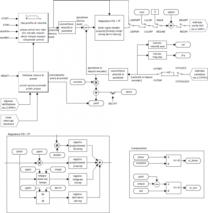
The internal ANPOS device is a tool that allows to manage the movement of a mechanical axis with a trapezoidal ramps to analog command.
-
The main function of the device is to generate a trajectory or 'speed profile' that if converted into a proportional voltage signal, commands the motor through a drive.
-
The device includes a feed-back process on the measurement taken from the position transducer. This measure compared to generate feedback.
-
The control voltage for operation is generated by a hardware DAC (Digital to Analogic Converter) of the BUS QMOVE.
-
To sync the device with the actual axis position returned by the axis, there is a special procedure for moving called 'presets search'.
-
The feed-back is the PID+FF type (proportional, integral, derivative and feed-forward).
Wiring and connections of the equipment described in this manual, muust comply with the European standard EN60204-1.
1.1 Installation
1.1.1 Device declaration in the configuration unit
In the configuration unit, the BUS section must be declared so that so that you have the hardware resources required for the implementation of the device ANPOS.
There must be at least a bi-directional counter and a 16-bit resolution analog output. The device can also used an input and an interrupt line for preset search functions.
In the INTDEVICE section of the configuration unit must be add the following definition:
;---------------------------------
; Device declarations
;---------------------------------
INTDEVICE
..
<device_name>  ANPOS  TCamp  ICont  IntL  IAZero  IOutA
 | It is necessary that each definition are present on the same line. In case you don't want to assign a resource, for example IAZero, you must enter in the appropriate field the X.X or X string. |
|---|
where:
| <device name> | Name assigned to device |
|---|---|
| ANPOS | Keyword that identifies the devices analog positioner. |
| TCamp | Sample time device 1÷255 ms) |
| ICont | Bidirectional counter input |
| IntL | Number of the interrupt line dedicated to the encoder zero pulse during the research phase of presets. Allowed values: 1÷8 (to prevent the device uses this resource, put the X character) |
| IAZero | Input of enabled to acquire the transducer's zero pulse during the preset search (to prevent device use this resource type the characters X.X) |
| IOutA | Hardware address of the DAC from analog output |
;---------------------------------
; Device declarations
;---------------------------------
INTDEVICE
Asse_X    ANPOS 2   2.CNT02  3  3.INP01  3.AN01
1.2 Operation
1.2.1 Position detection
The ANPOS device acquires the position of axis via bi-directional transmitter signals;
these signals are used by an internal counter. This counter does not show directly the position of the axis in the unit of measure required by your application.
The cntratio parameter is used to express the relationship between pulses
transducer and the corresponding application units. The permitted values for this parameter are 0,00374 ÷ 4 with five precision digits. The report must be introduced in
parameter as an integer, and then multiplied by 100000.
cntratio = (value in um) x 10 decimal digits / (corresponding transmitter pulse) x 100000
1.2.1.1 Decimal point
If for the selected measure unit is also provided for the presence of a decimal point, the positions must be represented always as an integer value and represent space on the measure unit without the decimal point. The resolution must be calculated with the same formula and the numerator the measure without decimal point. The decimal point will be entered in the value representing the time viewers (example as properties in the terminal operator).
1.2.1.2 Speed
The speeds are always expressed in whole units of measure in the unit of time choice. From this it emerges that the device must know the location of the decimal point of the unit of measure and this is done with the decpt parameter. This parameter can take 0÷3 values.
1.2.1.3 Example
| To activate this device send the INIT command. |
|---|
-
You want to represent the positions in centimeters with a decimal point.
-
In 18.2cm of the space the transducer generates 500 pulses.
To calculate the resolution you have to consider the space runs represented in terms of the measuring mm unit. For this the resolution is:
cntratio = (18.2 x 101 / 500) x 100000 = 36400
The settings must be:
Axis:cntratio = 36400
Axis:decpt = 1
To run a placement at 146 cm, put
Axis:setpos = 1460
For setting the 10 centimeters per second must put:
Axis:unitvel = 1
Axis:setvel = 10
1.2.2 Analogue output calibration
| Before starting actual placements you must make sure that electrical connections and mechanical appliances have not cause malfunctions. |
|---|
For axis management, thee ANPOS device using an analogue output with 16-bit resolution with 10 V range ± and sign; with the calibration function this analog output can be driven with a constant value in order to test links and functionality.
1.2.2.1 Preliminary motion
-
Remove the emergency condition with the RESUME command.
-
The st_emrg state = 0
-
Enable calibration axis status with the CALON command; the st_cal state must therefore take the value 1.
-
Now you can set the analog with voltage vout paramenter; the value is expressed in tenths of a volt (-100 ÷ 100 = -10 ÷ 10 V). It is recommended to introduce low values (5, 10, 15 … like 0.5, 1, 1,5 V).
-
When the axis is moving the frq parameter indicates the frequency in Hz of the transducer phases.
-
The parameter posit displaying the location, varies the space indicating axis. If setting a positive voltage the counter decreases, it is necessary to invert the phases of the transducer or reverse the drive directions.
-
You can reverse the direction of the count using the CNTREV command.
-
If output voltage equal to zero the axis is not stationary, adjust the offset parameter to correct the voltage until movement stops. The input value (each bit corresponds to approximately 0.3 mV), will be added algebraically to the value of the analogue output; This operation allows to compensate for any drift in the electronic component, and output from QMOVE that entering the drive. The value is expressed in bits with sign.
For an optimal result of calibration this operation must be performed with the system to temperature capacity.. -
To disable calibration status send the CALOFF command.
-
The state st_cal = 0
1.2.2.2 Output settings
The ANPOS device raises the voltage value of the analogue output on the basis between the maximum speed of the axis and the maximum output voltage proportion. La proporzionalità è ottenuta with the maxvel parameter, maximum axis speed representative on the analog voltage (10 V). The axis must behave symmetrical analog voltage to zero, therefore the speed must be the same on both the positive and negative voltage at maximum.
Before you determine the value of the maximum speed, must establish the unit of time to use for the representation of the speed in the device; the unitvel parameter defines the unit of time of speed (Um/min or Um/s).
1.2.2.3 Theoretical method for maximum speed determination
The theoretical method is a calculation that was performed on the basis of the maximum speed of the motor. Set the maximum revolutions per minute engine declared, we get the maximum speed.
Setting in the maxvel parameter the maximum speed value calculated.
1.2.2.4 Convenient way to determine the maximum speed
The practical way is based on the reading of the speed detected by the device in the vel variable, giving the drive a voltage. To provide the voltage to drive the device should be placed in a position of calibration as described in the previous paragraph. If the system permits, supply voltage operation of 10 V and read the speed value in the vel parameter. If, on the backwards, is an excerpt of the output voltage (1, 2, … 5 V), calculate the maximum speed with the proportion: vout : 10 [V] = vel : maxvel
Enter the maximum speed value found in maxvel parameter.
1.2.3 Handling
| Before handling the Board, check the proper operation of emergency equipment and protection. |
|---|
The procedures were allowed to complete the first phase of device settings. Now you can run smooth movement of the axis.
-
Move the axis in a position whereby it can fulfill a certain area without touching the maximum quota limit.
-
Set the current position of the axis to zero, by setting the posit parameter = 0.
-
Set up the parameters that define the position of the limit switches software: minpos = 0 and maxpos to the value of the maximum stroke of the axis.
-
Set the parameter that defines the time from the axis to reach the maximum speed taccdec = 100. This parameter is expressed in hundredths of a second (100 = 1 sec.)
-
Set the speed of positioning with the setvel parameter.
-
Set the target altitude with the setpos parameter.
-
Set the feedforward parameter = 1000 (100%)
-
If the device is in Emergency State of (st_emrg = 1) give the RESUME command.
-
Start positioning with the START command. To stop the movement give the EMRG command.
This first movement was done without speed feedback space. The placement may have been executed with some error introduced by the non-linearity of the components or imperfection in the maximum velocity calibration. Then if you enable feedback of space this error goes away.
1.2.4 PID+FF adjustment
The placement made in the preceding paragraph has been made without considering any position errors.
To check the correct position of the axis continuously and automatically, you must
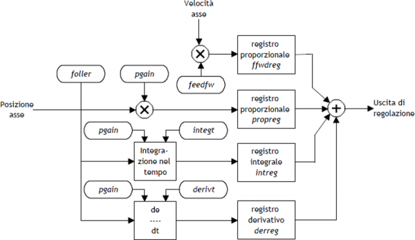
have a feed-back on the position; for this reason introduces the control PID + FF algorithm including proportional, integral, derivative actions and feed-forward; the value of the analog output is given by the summation of actions feed forward, proportional, derivative and integrative.
This section describes a series of actions to adjust the parameters that affect this control.
In order to achieve a satisfactory adjustment is sufficient to use only the feedforward and proportional actions; integral and derivative actions are used only for adjustments under special conditions.
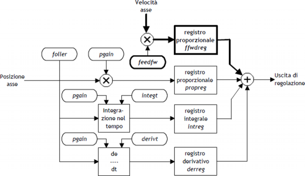
1.2.4.1 Feed forward action
The feed-forward helps make the system more ready on positioning, by providing the analog output voltage proportional to the theoretical speed of positioning.
The contribution of this action can be adjusted with the feedfw parameter; this parameter is expressed as a portion of millesimal theoretical speed; so, to introduce such as 98.5% you must set 985 (MILS).
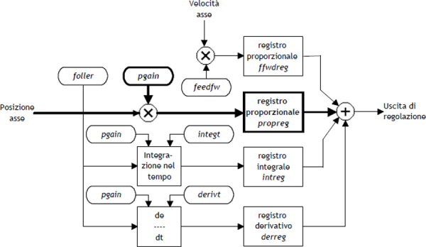
1.2.4.2 Proportional action
This action provides an proportional output to the instantaneous axis position error. The size of the proportional action is defined by the pgain parameter that defines the sensitivity of the system.
The pgain parameter is introduced in thousandths; the unit value of the gain (1000) provides an analog output to maximum value (10 V) concerning the maximum speed error. For maximum speed error means the space taken by axis - at the max speed - for the duration of the sampling time of the device.
1.2.4.3 Integral action
Integrates the position error of the system over time set in integt parameter updating the output until the error is reset.
More decreases the integration time of the error, more faster the recovery system error,
but the system may become unstable and swung.
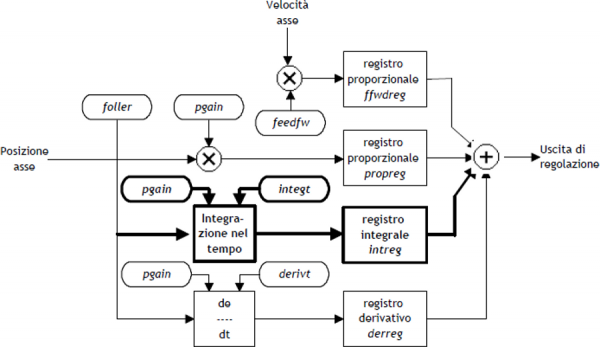
1.2.4.4 Derivative action
Anticipates the change of the motion of the system tends to eliminate the overshoot the positioning.
The size of change is calculated over time set in derivt parameter.
More higher the time of derivation of error and more faster is the transient error recovery system, But if you enter a value that is too high the system becomes unstable, tending to fluctuate.
1.2.5 Search Preset
Searching for presets is a procedure to synchronize the counter (posit parameter) with the real position of the axis. Can be performed in 3 different ways according to the prsmode parameter.
1.2.5.1 Preliminary considerations
-
In order to execute a search preset input is needed (acquired via the QMOVE BUS) we call 'enabling zero transducer'. In this trajectory, the axis must activate this input into a particular point.
-
The preset search procedure is started with the PRESET command; early counting from QMOVE can have any value and can be located anywhere.
-
The axis must direct towards the cam allows the upload of preset. Not knowing which way to direct the axis to meet the enable input, search for preset lets you choose two solutions with the prsdir parameter:
prsdir =0 the axis will always a movement forward
prsdir =1 the axis will always a movement back -
If during the preset search is given a PRESET command, the direction of motion of the axis is reversed.
-
Note that the share of presets contained in the prspos parameter must be always between the minimum and the maximum quota and after the preset quota load, the axis is automatically positioned to the preset quota.
-
When searching preset the software limits maxpos and minpos are disabled.
-
When you set the search speed zero pulse - sprsvel - we must consider that in the 0 Mode the input has a hardware filter that delays the acquisition and therefore influence the precision of the loading. In the 1 Mode, the acquisition is made on interrupt input, so the speed is not determinative. We must ensure that the operating time of the zero-pulse is sufficient to be acquired from the card. In order to know the acquisition time of the entrance and the minimum time of zero pulse signal refer to the technical documentation of the used cards.
If enable the preset search with the PRESET command, the axis towards the position where you active the enable zero-pulse input of transducer with speed define by prsvel. The st_prson state you turn to report the current preset. When, in this motion, the axis active the input, reverses direction and starts with sprsvel speed.
The operation depends from the selected mode of loading (Mode 0 or Mode 1).
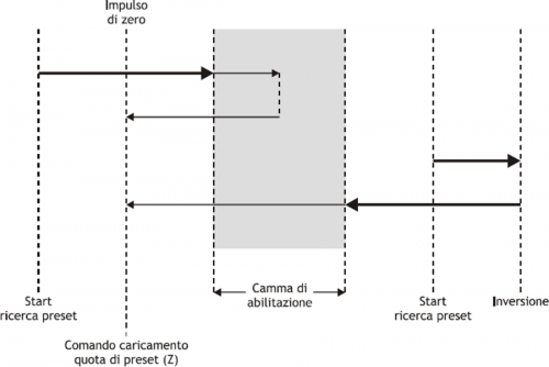
1.2.5.2 Preset search - Mode 0
| This procedure involves the movement of the axis and the use of the zero pulse enable input of the transducer. |
|---|
The deactivation of the enable input zero-pulse transducer, the preset quota is loaded on the counter (parameter posit=prspos).
Next, you disable the st_prson status and activate the st_prsok state to signal the end of search. This state remains active until the starting of a new procedure of presets; at the system startup this State is always to zero. See the picture 1.
| Picture 1: Loading presets using the only enabling cam. |
 |
1.2.5.3 Preset search - Mode 1
| This procedure involves the movement of the axis and the use of the zero pulse and zero pulse enable input of the transducer. |
|---|
At the deactivation of the enable input zero-pulse transducer, enables reading of the first zero-pulse provided by the transducer and on this signal, loads the preset quota in counting (parameter posit=prspos).
To load the share presets with 'Mode 1', the card which is attached to the zero-pulse trasducer must transmit this signal on one of the 8 hardware interrupt lines. The device must have been defined to use the same hardware interrupt line (see the definition in the .CNF file).
Subsequently, the axis is positioned at an presets quota, to disable the st_prson state and enable the st_prsok state for to signal the end of search; This State remains active until the starting of a new preset procedure. At the startup of the instrument the st_prsok parameter is always to zero. See the picture 2.
| Picture 2: Loading presets using the enable cam and the zero pulse of transducer. |
 |
1.2.5.4 Preset search - Mode 2
| This procedure does not provide for the handling of the axis and the use of the zero pulse enable transducer input. |
|---|
With this procedure, the search for preset does not perform any positioning. The load command of the preset quota is provided by the activation of the enable zero encoder input and the st_prsok state is set to one.
If the input is active, the load is continuously, while if at the startup the input is already active, the first upload is executed only after its deactivation and activation.
1.3 Special functions
1.3.1 Multi-axis management
In some applications are required to place a large number of axes by moving a single axis at a time. The design choice falls on installing just one drive that depending on the axis to be placed electrically connects the motor interested in positioning; the transducer is always bound to its axis.
The ANPOS device allows you to control access to the DAC device REGON and REGOFF commands. In this way through the QCL application defines a set of device many axes to be placed; in the definition, all devices use the same DAC resource. (IOutA).
Normally all devices must be in the st_regoff = 1 state so you will not have access to the DAC apparatus. Before you start positioning, with the REGON command, the device is brought to the st_regoff = 0 state. Runs the positioning and, at the completion, the device is returned in the st_regoff = 1 State with the REGOFF command.
For no reason two devices simultaneously must be found in the st_regoff =0
state.
When the device is placed in the regoff position, the analog output remains fixed at the last voltage value called before the REGOFF command.
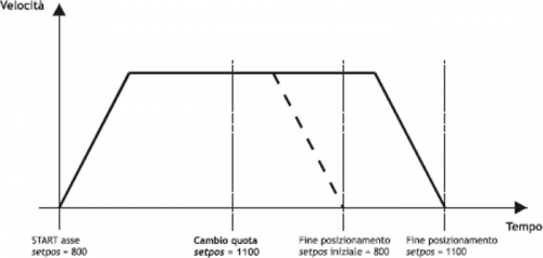
1.3.2 Change quota and counting in motion
| Changing the quota is accepted only if the new position is reached with direction in use and if the axis is not already when slowing down to reach the quota previously set. |
|---|
In some applications is needed to define the target quota during the motion, according to external events to the device. This feature translates into the ability to write to the current setpos parameter even with current placements.
When positioning you can also change the value of the posit counter. This function is usually used when a device must under certain conditions, continue a speed profile for a very long time, that exceeds the time axis takes to reach the limit quota (maxpos or minpos).
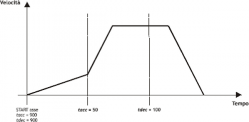
1.3.3 Change speed and moving ramp time
When positioning it is possible to vary the speed of the axis without affecting the location to get to. This operation can lead to an increase or a decrease in velocity, even more points with the same placement. This operation is accomplished with new writing in the setvel parameter.

When positioning can be varied even acceleration/deceleration times. For example, the device can start a placement with a very short ramp and once they reach the speed set, varied the tacc parameter and do a change of speed with a very long ramp.
For special applications the ramp time can be varied even during a change of speed, in this case the new time is put into immediately execution.
1.3.4 Delta counter
| The command can be sent only if the axis is stopped, condition of st_still = 1. |
|---|
The device always shows the absolute position of the axis; to execute the incremental placements is need a tool to subtract or add some value to the count (posit) without introducing errors. The change can also count with a direct writing to the new value in the posit parameter.
Wanting to steal 100 units of measure from the counter you can:
Axis:posit = Axis:posit - 100
| The changing at the value of resolution (cntratio) or the writing of the posit variable, causes the reset of the remnants of the conversion. |
|---|
This operation introduces an error because it imposes the location 'posit = -100', when the axis could have an intermediate position between a unit of measurement and subsequent (ex. 100.3). This fraction (0.3) is lost and the repetition of these steps will the accumulation of a considerable error.
The DELCNT command sum the count an amount equal to the parameter delta without losing the fraction part of the position:
Axis:delta = -100
DELCNT Axis
The DELCNT command may be sent only with stationary axis (st_still=1)
1.3.4.1 Example
The axis position is of 2 units and is located at point A. You want to add to the posit counter three measure units.
With instructions:
Axis:posit = Axis:posit + 2
the axis takes the new B position.
With instructions :
Axis:delta = 2
DELCNT Axis
C position is reached.
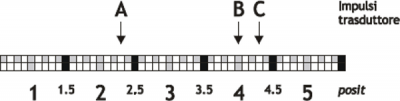
Note that with the first instructions the axis took a delta less than 3 units and this introduced an error.
If you need to send the succession DELCNT commands, It is convenient to calculate the value to be summed and send once the command; otherwise beware not to send subsequent commands without a read statement on device parameter.
1.3.4.2 Example
Axis:delta = 3
DELCNT Axis
WAIT Axis:st_init
Axis:delta = 40
DELCNT Axis
1.4 Commands and parameters table
1.4.1 Symbols used
The parameter name, condition or command is taken back to the left side of the table.
R
Indicates whether the parameter or state is retentive (upon initialization of the device maintains the previously defined state), or the state assumes upon initialization of the device.
If the device does not need to initialize the 'R' field dicates the value that the parameter or state accept to the startup card.
R = Retentive
0 = Upon initialization of the device the value is forced to zero.
1 = Upon initialization of the device the value is forced to one.
- = Upon initialization of the device is presented significant value.
D
Indicates the size of the parameter.
F = Flag
B = Byte
W = Word
L = Long
S = Single Float
1.4.1.1 Conditions
Describes all the conditions necessary so that the parameter is considered correct or because the command is accepted.
In some cases, limit values are specified for the acceptance of the parameter: if set any values outside the limits, the data is accepted; but must be monitoring the application that provided to ensure the proper functioning.
To run a command, all the conditions must be met; otherwise the command does not run.
A
Indicates the access mode.
R = Read.
W = Write.
RW = Read / Write.
1.4.2 Commands
Controls were ranked by decreasing priority. For example, in the case of contemporary INIT and EMRG controls, is acquired first the INIT command.
| Name | Conditions | Description |
|---|---|---|
| INIT | st_init = 1 | Initialization Initializing command device. If the device is not initialized does not perform the calculations related to the axis and then sits idle. To startup you can download all parameters in DPR; then, with the INIT command the axis will be inizialiazzato, by performing the calculations only once. Enable the st_init state. |
| EMRG | st_init = 1 | Emergency Emergency stopping axis poses, without deceleration ramp, any ongoing positioning. It also disabled the axis space reaction. |
| RESUME | st_init = 1 st_emrg = 1 | Resume Restore of emergency condition of axis; it's enable the axis space reaction. To the start, the axis resume the the positioning. |
| START | st_init = 1 st_regoff = 0 st_emrg = 0 st_cal = 0 st_still = 1 | Start Controls the positioning to the setpos quota and setvel speed. |
| STOP | st_init = 1 st_regoff = 0 st_emrg = 0 st_cal = 0 st_still = 0 | Stop Stops any ongoing axis positioning. The axis stop follows the deceleration ramp in use. The axis remains in reaction to space. |
| LOOPON | st_init = 1 | Loop ON Enables the reaction of space axis. The analog output sharpen every external action that attempts to move the axis from the reached position (drift, user, …). This operation resets any tracking follerr error. |
| LOOPOFF | st_init = 1 | Loop OFF Disable the reaction of space axis. The axis can be moved from this position without that the analogue output contrasts the movement. |
| CNTLOCK | st_init = 1 | Counter lock Blocks the acquisition of axis counter even if the transducer continues to send signals. At this stage the axis shift is not detected. Disables loading of presets on the counter. Activates the st_cntlock state. |
| CNTUNLOCK | st_init = 1 | Counter unlock Unlock the axis counter. Resumes reading of the signals sent from the transducer and the updating counter. Disable the st_cntlock state. |
| CNTREV | st_init = 1 | Counter reverse Invert the phases of the transducer in the card. Reverses the direction of the count (increase/decrease). Activates the st_cntrev state. |
| CNTDIR | st_init = 1 | Counter direct Counting the axis is reversed. Disable the st_cntrev state. |
| PRESET | st_init = 1 st_regoff = 0 st_emrg = 0 st_cal = 0 st_still = 1 | Preset Start axis presets search. Start to preset search procedure in the way set with prsmode and prsdir parameters. If the preset search is already running, the command performs the reverse search. Activates the st_prson state and disable the st_prsok state. |
| CALON | st_init = 1 | Calibration ON The analog output is used as a voltage source; in this case you cannot use it for positioning the axis. The output value is settable at will through the vout variable. |
| CALOFF | st_init = 1 st_cal = 1 | Calibration OFF The analog output is not used as voltage generator, so it can be used for managing placements. |
| MANFW | st_init = 1 st_regoff = 0 st_prson = 0 st_still = 1 | Manual forward Controls the forward manual positioning (towards maxpos) the set speed. |
| MANBW | st_init = 1 st_regoff = 0 st_prson = 0 st_still = 1 | Manual backward Controls the back manual positioning (towards minpos) the set speed. |
| REGOFF | st_init = 1 st_still = 1 | Regulation OFF Disable the adjustment and upgrading of the DAC, as well as all the movement commands. |
| REGON | st_init = 1 st_regoff = 1 | Regulation ON Restorte the adjustment and updating the DAC, as well as all the movement commands. |
| DELCNT | st_still = 1 st_init = 1 | Delta counter This command is accepted only if the axis is stopped; the counter (axis position) is modified by adding algebraically the value specified in the delta variable. |
1.4.3 Parameters
| Name | D | R | A | Conditions | Description |
|---|---|---|---|---|---|
| cntratio | L | R | R-W | st_still = 1 | Counter ratio Defines how the transducer pulses must be multiplied so that the acquisition of movements is expressed in the unit of measure desired. By setting the count variation is 100000 1 bit per pulse transducer. Valid Range: 347 ÷ 400000 |
| maxpos | L | R | R-W | st_still = 1 | Maximum position Defines the maximum quota reached by the axis; the value set is to be considered also as an upper limit for the introduction of quotas of work. Value expressed in units of measurement (Um). Valid Range: -999999 ÷ 999999 |
| minpos | L | R | R-W | st_still = 1 | Minimum position Defines the minimum quota reached by the axis; the set value is considered as the lower limit for the introduction of quotas of work. Value expressed in units of measurement (Um). Valid Range: -999999 ÷ 999999 |
| prspos | L | R | R-W | st_still = 1 | Preset position Defines the value that is loaded on the counting with the preset search procedure. Valid Range: minpos÷maxpos |
| maxvel | L | R | R-W | st_still = 1 | Maximum velocity Defines the maximum speed axis (analogue reference +/-10V). The value is per unit of time of the set speed Velocity unit. Value expressed in Um/s or Um/min. Valid Range: 0 ÷ 999999 |
| prsvel | L | R | R-W | st_still = 1 | Preset velocity Defines the speed of the axis during the search procedure of presets. The input value is per unit of time of the set speed (Velocity unit). Valid Range: 0 ÷ maxvel |
| sprsvel | L | R | R-W | st_still = 1 | Preset search velocity In the preset search procedure, defines the axis speed in the acquisition zero-pulse phase. The input value is per unit of time of the set speed (Velocity unit). Valid Range: 0 ÷ prsvel |
| toll | L | R | R-W | st_still = 1 | Tolerance Defines a count range around locating dimensions. If the placement ends within this range, it is considered correct. Value expressed in (Um). Valid Range: -999999 ÷ 999999 |
| maxfollerr | L | R | R-W | None | Maximum following error Defines the maximum acceptable deviation between the theoretical position and the actual position of the axis. Value, in bits, transducer. Valid Range: 0 ÷ 2147483648 |
| rampmode | B | R | R-W | se st_still = 1 writing always enable, if st_still = 0 the new value is stored but processed only if the new time of acc. and dec. allow to reach the set quota. | Acceleration/deceleration time mode Used when choosing between acceleration and deceleration ramps equal or differentiated. Allowed values: 0 = equal ramps 1 = differentiated ramps |
| taccdec | W | R | R-W | se st_still = 1 writing always enable, if st_still = 0 the new value is stored but processed only if the new nuovi tempi of acc. and dec. allow to reach the set quota. | Acceleration/deceleration time Is the time required to go from 0 speed to maximum velocity and vice versa; the parameter is used if rampmode = 0. Value expressed in hundredths of a second. Valid Range: da 0 a 999 |
| tacc | W | R | R-W | se st_still = 1 writing always enable, if st_still = 0 the new value is stored but processed only if the new time allows you to reach the setting quota | Acceleration time Defines the necessary time for the axis to accelerate from zero to maximum speed (condition of stopped axis) at maximum speed. Value expressed in hundredths of a second. Valid Range: from 0 to 999 |
| tdec | W | R | R-W | se st_still = 1 writing always enable, if st_still = 0 the new value is stored but processed only if the new time allows you to reach the setting quota. | Deceleration time Defines the necessary time for the axis to decelerate from maximum speed to zero (condition of stopped axis). Value expressed in hundredths of a second. RaValid Range: from 0 to 999 |
| tinv | W | R | R-W | None | Direction inversion delay Is used to avoid mechanical stress caused by too rapid direction changes movement. Value expressed in hundredths of a second. Valid Range: from 0 to 999 |
| toldly | W | R | R-W | None | Tolerance delay Defines the time between the arrival of the axis in the tolerance range and its status report. Value expressed in hundredths of a second. Valid Range: from 0 to 999 |
| pgain | W | R | R-W | None | Proportional gain If set the 1000 value, the coefficient is 1,000 Is the factor that is multiplied against the tracking error produces the proportional portion of control output. Valid Range: from 0 to 32767 |
| feedfw | W | R | R-W | None | Feed forward If set the 1000 value, the percentage is 100%. Is the coefficient percentage that multiplied by the speed, generates the feed-forward control output. Valid Range: from 0 to 32767 |
| integt | W | R | R-W | None | Integral time Is the time, in milliseconds, that produces the basic integration of tracking error. The integration of that error multiplied by that coefficient raises the integral part of the control output. Valid Range: from 0 to 32767 |
| derivt | W | R | R-W | None | Derivative time Is the time, in milliseconds, that produces the coefficient derivative of the tracking error. The derivation of that error multiplied by that coefficient raises the integral part of the control output. Valid Range: from 0 to 32767 |
| prsmode | B | R | R-W | None | Preset mode Defines the type of preset search: 0 = For research of enabling zero-pulse, the axis movement begins in speed, bump into the cam by enabling, reverses the direction of slowing and, on the cam front relative at the signal drop, loads the preset quota. 1 = For research of enabling zero-pulse, the axis movement begins in speed, bump into the cam by enabling, reverses the direction and slowly acquires the first zero-pulse (After disabling of the cam signal). 2 = Does not activate the search procedure presets with axis handling. The counter is updated at the presets to the activation of the enabling zero-pulse. |
| prsdir | B | R | R-W | None | Preset direction Defines the direction of movement of the cam for the research of the zero axis pulse enable. 0 = the axis goes forward. 1 = the axle head back |
| unitvel | B | R | R-W | st_still = 1 | Velocity unit Defines if time unit of speed is expressed in minutes or seconds. 0 = Um/min 1 = Um/sec |
| decpt | B | R | R-W | st_still = 1 | Decimal point Defines the accuracy with which you wish to set the presets and view the counts in relation to the axis. Valid Range: from 0 to 3. |
| offset | W | R | R-W | None | Offset DAC output offset in bits. Defines the bit value of the analog output correction in order to compensate for any drift in the system. Value, in bits DAC. Valid Range: from -32768 to 32767 |
| setpos | L | R | R-W | se st_still = 1 writing always enable, if st_still = 0 writing enabled if the new quota can be achieved with the same direction of positioning. The parameter is altered if done a search of presets with prsmode = 0 o 1. | Setted position Defines the placement quota reached from the x axis at setvelx velocity. Valid Range: from minpos to maxpos N.B.The value is altered if you tell the enquiry procedure presets search with prsmode = 0 o 1. |
| setvel | L | R | R-W | se st_still = 1 writing always enable, if st_still = 0 the new value is stored but processed only If the axis is not in deceleration to reach the setting quota. The parameter is altered if done a search of presets with prsmode = 0 o 1. | Setted velocity Is the of positioning speed value. Value expressed in Um/s or Um/min. Valid Range: 0 ÷ maxvel |
| vout | B | 0 | R-W | st_cal = 1 | Volt out It's the output voltage value is expressed in tenths of a volt, to be used in the calibration procedure. Valid Range: -100 ÷ 100 |
| vel | L | 0 | R | None | Velocity Is the value of the instantaneous speed of the axis. Value expressed in Um/s or Um/min. |
| frq | L | 0 | R | None | Frequency Is the value of the instantaneous frequency of the axis. Value expressed in Hz. |
| posit | L | R | R-W | se st_still = 1 writing always enable, if st_still = 0 the new value is processed only if the axis is not decelerating to reach the setting quota. | Actual position Is the value of the instantaneous position of the axis. Value expressed in (Um). |
| follerr | L | 0 | R | None | Following error Is the instantaneous value of the tracking error. Value, in bits, transducer. |
| ffwdreg | L | 0 | R | None | Feed-forward register Is the instantaneous value of the register of feed-forward, expressed in bits. |
| propreg | L | 0 | R | None | Proportional register Is the instantaneous value of the register proportional expressed in bits. |
| intreg | L | 0 | R | None | Integral register Is the instantaneous value of the integral register expressed in bits. |
| derreg | L | 0 | R | None | Derivative register Is the instantaneous value of the register derivative, in bits. |
| delta | L | R | R-W | None | Delta counter Is the value that is added to the count when sending a DELCNT command. Value expressed in (Um). Valid Range: -999999 ÷ 999999 |
1.4.4 States
| Name | D | R | A | Conditions | Description |
|---|---|---|---|---|---|
| st_init | F | 0 | R | None | Initialization Reporting of device initialized. 0 = device is not initialized. 1 = device initialized. To startup by default loads the value zero. |
| st_emrg | F | 0 | R | None | Emergency Reporting of axis in an emergency. 0 = axis not in emergency. 1 = axis in emergency. |
| st_toll | F | 0 | R | None | Tolerance Reporting of axis in tolerance in relation to the share put in execution by the START command. Signaling axis in tolerance may be delayed with toldly parameter. 0 = axis not in tolerance. 1 = axis in tolerance. To startup by default loads the value zero. |
| st_prsok | F | 0 | R | None | Preset Ok Reporting of axis in tolerance in relation to the share put running from the START command. Signaling axis in tolerance may be delayed with toldly parameter. 0 =axis not in tolerance. 1 = axis in tolerance. To startup by default loads the value zero. |
| st_still | F | 0 | R | None | Still Signalling of stationary axis. 0 = moving axis. 1 = axis stopped. To startup by default loads the value 1. |
| st_prson | F | 0 | R | None | Preset ON Axis preset search ongoing reporting. 0 = preset search not in progress. 1 = preset search in progress To startup by default loads the value zero. |
| st_movdir | F | 0 | R | None | Movement direction Indication of the direction of movement. 0 = forwards. 1 = backwards. To startup by default loads the value zero. |
| st_loopon | F | 0 | R | None | Loop ON Reporting of axis in reaction to space. 0 = axis not in reaction to space. 1 = axis in reaction to space. To startup by default loads the value zero. |
| st_foller | F | 0 | R | None | Following error Axis tracking error signal (restrain 500 ms). 0 = axis not in tracking error. 1 = axis in tracking error. To startup by default loads the value 1. |
| st_regoff | F | 0 | R | None | Regulation Indicates that the setting is disabled and that upgrading the DAC is not performed. |
| st_cal | F | 0 | R | None | Calibration Reporting of axis as voltage source. 0 = voltage source axis disable. 1 = voltage source axis enable. To startup by default loads the value zero. |
| st_cntlock | F | R | R | None | Counter locked Reporting of unlocked axis. 0 = unlocked axis counter. 1 = blocked axis counter. |
| st_cntrev | F | R | R | None | Counter revers Inverted axis counter report. 0 = Axis count not inverted. 1 = Axis count inverted. This status is maintained at power-off. |
| st_cntrev | F | R | R | None | Counter revers Inverted axis count report. 0 = Axis count not inverted. 1 = Axis count inverted. This status is maintained at power-off. |
1.5 Limitations
No limitation
1.6 Application example
1.6.1 The configuration file
;*************************************************************************************
; Module Name: Ex_Anpos.CNF                 Project: Ex_ANPOS
; Autor: QEM srl                            Date: 01/05/99
; System: QMove1 / QCL3                     Library: 1LIB3B04
; Functionality: ANPOS management example   Release: 0
;------------------------------------- Note ------------------------------------------
; [1] - Sample application using device ANPOS
**************************************************************************************

;-------------------------------------------------------------------------------------
; Constants Defining
;-------------------------------------------------------------------------------------
CONST

;-------------------------------------------------------------------------------------
; Variable Definition SYSTEM
;-------------------------------------------------------------------------------------
SYSTEM
slQuotaPos   L                          ;Variable for placement quota
slVelAsse   L                           ;Variable for axis speed

;-------------------------------------------------------------------------------------
; Variable Definition GLOBAL
;-------------------------------------------------------------------------------------
GLOBAL
gfMovMan   F                            ;Flag signalling movements
                                        ;manuals in progress
gfMovAuto   F                           ;Flag signalling movements
                                        ;ongoing automatic

;-------------------------------------------------------------------------------------
; Variable Definition TIMER
;-------------------------------------------------------------------------------------
TIMER

;-------------------------------------------------------------------------------------
; Definition DATAGROUP
;-------------------------------------------------------------------------------------
;DATAGROUP
;-------------------------------------------------------------------------------------
; Bus Configuration
;-------------------------------------------------------------------------------------
BUS
     1  1CPUB   02
     2  1MIXA   00
     3  .
     4  .

;-------------------------------------------------------------------------------------
; Variable Definition INPUT
;-------------------------------------------------------------------------------------
INPUT
ifAvMan     F    2.INP01                ;Forward manual input
ifInMan     F    2.INP02                ;Backrìward manual input
ifStart     F    2.INP03                ;START input axis
ifStop      F    2.INP04                ;STOP input axis

;-------------------------------------------------------------------------------------
; Variable Definition OUTPUT
;-------------------------------------------------------------------------------------
OUTPUT
ofToll      F    2.OUT01                ;Output shaft tolerance
ofAxeFermo  F    2.OUT02                ;Output of stopped axis

;-------------------------------------------------------------------------------------
; Device declaration
;-------------------------------------------------------------------------------------
INTDEVICE
;Name   Type   TCamp   Counter   Inter   AbilZero  OutAnal
Asse    ANPOS  0004    2.CNT01     1       2.INP01   2.AN01

END
1.6.2 ANPOS management
;*************************************************************************************
; File Name: TASK_00.MOD
; Project : EX_ANPOS
; Description: Positioning Management
;*************************************************************************************

;-------------------------------------------------------------------------------------
; Initialization work Axis
;-------------------------------------------------------------------------------------
Axis:cntratio = 100000                     ;Encoder resolution = Space in 1 tourn
                                           ;encoder(Um) / tourn pulse encoder
Axis:maxvel = 100000                       ;Max. speed = Axis speed with
                                           ;10V analog output (CALON/
vout=100)
Axis:maxpos = 999999                       ;Maximum quota
Axis:minpos = -999999                      ;Minimum quota
Axis:maxfollerr = 10000                    ;Tracking error
Axis:unitvel = 0                           ;Unit time speed
Axis:decpt = 0                             ;Decimal digits
Axis:rampmode = 0                          ;Type of used ramps
Axis:taccdec = 100                         ;Acceleration and deceleration time
Axis:tacc = 0                              ;Acceleration time (not used)
Axis:tdec = 0                              ;Deceleration time (not used)
Axis:tinv = 0                              ;Inversion axis time
Axis:toll = 5                              ;Tolerance
Axis:toldly = 10                           ;Time delay activation tolerance
Axis:prsmode = 0                           ;Preset search type
Axis:prspos = 0                            ;Preset quota
Axis:prsdir = 0                            ;Preset search direction
Axis:prsvel = (20 * Asse:maxvel)/100       ;Preset speed (20% of the
max. speed)
Axis:sprsvel = (10 * Asse:maxvel)/100      ;Pulse speed zero
                                           ;search (10% of the max. speed)
Axis:offset = 0                            ;Offset voltage
Axis:pgain = 10                            ;Proportional gain
Axis:feedfw = 1000                         ;Feedforward
Axis:integt = 0                            ;Integral time
Axis:derivt = 0                            ;Derivative time
INIT Axis                                  ;Initializes the device
WAIT Axis:st_init                          ;Wait until the device is initialized
CNTUNLOCK Axis                             ;Unlock counter
WAIT NOT Axis:st_cntlock                   ;Wait until the count is unlocked
CNTDIR Axis                                ;Sets the direction of the counter
WAIT NOT Axis:st_cntrev                    ;Wait until it is set the direction
                                           ;of the counter
REGON Axis                                 ;Enable the adjustment
WAIT NOT Axis:st_regoff                    ;Wait for enabling regulation
RESUME Axis                                ;Remove the axis from the emergency state
WAIT NOT Axis:st_emrg                      ;Wait until the axle is not in emergency
LOOPON Axis                                ;Snap reaction shaft loop
WAIT Axis:st_loopon                        ;Wait that is hooked on loop
                                           ;reaction of the axis
IF (slVelAxis EQ 0)                        ;In case the set of speed
                                           ;the axis is zero
  slVelAxis = 50                           ;Sets a positioning speed
ENDIF
IF (slQuotaPos EQ 0)                       ;In the event that the quota of
                                           ;positioning the axis is to zero
  slQuotaPos = 2000                        ;Sets a quota of positioning
ENDIF

;-------------------------------------------------------------------------------------
; Positioning tasks
;-------------------------------------------------------------------------------------
; ------------------------------- used variables -------------------------------------
; slVelAxis: Adjustable variable that represents the axis speed
; (declared in % of the max. speed)
; slQuotaPos: Adjustable variable that represents the share of axis positioning
; ---------------------------------- used flags----- ---------------------------------
; gfMovMan: manual operation in progress
; gfMovAuto: Automatic movement in progress
;-------------------------------------------------------------------------------------
MAIN:
;-------------------------------------------------------------------------------------
; Outputs management
;-------------------------------------------------------------------------------------
ofToll = Axis:st_toll                   ;Sets the output of tolerance as
                                        ;the tolerance state
ofAxeFermo = Axis:st_still              ;Sets the output of stationary axis as
                                        ;the status of stationary axis

;-------------------------------------------------------------------------------------
; Automatic movements managing
;-------------------------------------------------------------------------------------
IF ifStart                                      ;Waits for the START input
  IF NOT gfMovMan                               ;Check that there are no movements
                                                ;manuals
    IF Axis:st_still                            ;Check that the axis is stopped
      Axis:setvel=(slVelAxis*Axis:maxvel)/100   ;Sets the axis speed
      Axis:setpos = slQuotaPos                  ;Sets the placement quota
      START Axis                                ;Run the start of axis
      gfMovAuto = 1                             ;Automatic movement in progress reports
    ENDIF
  ENDIF
ENDIF
IF ifStop                                       ;Waits for the STOP input
  IF NOT Axis:st_still                          ;Check that the axle is not stationary
    STOP Axis                                   ;Run the stop of the axis
  ENDIF
ENDIF
IF gfMovAuto                                    ;Check reporting movement
                                                ;ongoing automatic
  IF Axis:st_still                              ;Check that the axis is stopped
    gfMovAuto = 0                               ;Reset status of automatic movement
  ENDIF
ENDIF

;-------------------------------------------------------------------------------------
; Manual movements management
;-------------------------------------------------------------------------------------
IF ifAvMan                                      ;Awaiting the entry of manual operation
  IF NOT (gfMovAuto OR gfMovMan)                ;Check that there are no movements
                                                ;automatic or manual
    IF Axis:st_still                            ;Check that the axis is stopped
      Axis:setvel=(slVelAxis*Axis:maxvel)/100   ;Sets the axis speed
        MANFW Axis                              ;Forward axis in manual
        gfMovMan = 1                            ;Manual movement in progress reports
      ENDIF
    ENDIF
ENDIF
IF ifInMan                                      ;Awaiting the entry of manual operation
  IF NOT (gfMovAuto OR gfMovMan)                ;Check that there are no movements
                                                ;automatic or manual
    IF Axis:st_still                            ;Check that the axis is stopped
      Axis:setvel=(slVelAxis*Axis:maxvel)/100   ;Sets the axis speed
      MANBW Asse                                ;Forward axis in manual
      gfMovMan = 1                              ;Manual movement in progress reports
    ENDIF
  ENDIF
ENDIF

IF gfMovMan                                     ;If the axis moves in manual
  IF NOT (ifAvMan OR ifInMan)                   ;If the inputs of forwards or backwars
                                                ;Manual are OFF
    STOP Axis                                   ;Stop the axis
    gfMovMan = 0                                ;Remove the reporting of axis
                                                ;Manual movement
  ENDIF
ENDIF
;-------------------------------------------------------------------------------------
; Final operations
;-------------------------------------------------------------------------------------
  WAIT 1
  JUMP MAIN
END