DEVICE COUNTER2
1. Introduction
-
The internal device COUNTER2 is one tool that resides in the CPU that allows to manage the acquisition of count of a bidirectional incremental transducer.
-
The value is converted internally into space and proposed in the unit of your choice to the user.
-
Includes the functions of delta DELCNT incremental placements count and capture of the count on hardware interrupts.
Wiring and connections of the equipment described in this manual, shall comply with the European standard EN 60204-1.
1.1 Installation
1.1.1 Device declaration in the configuration file (.CNF)
In the configuration file (.CNF), the BUS section must be declared so that you have the hardware resources required for the implementation of the COUNTER2 device. There must be at least one bidirectional meter. The device can also use an interrupt line for the snap functions count on interrupt (such as uploading preset quota).
In the INTDEVICE section of the .CNF file must be added the following definition:
;---------------------------------
; Internal device declaration
;---------------------------------
INTDEVICE
..
<device_name> COUNTER2 TCamp QCTL IntL
 | It is necessary that each definition are present on the same line. In case you do not want to assign a resource such as IntL, you still must enter in the appropriate field the string X. |
|---|
where:
| <device name> | Name assigned to the device. |
| COUNTER2 | Keyword that identifies the device bi-directional meter. |
| TCamp | Sample time device (1÷255 ms). |
| QCTL | Address tab counter. |
| IntL | Hardware interrupt line number dedicated for transducer zero pulse during the capture phase of the count (to prevent the device uses this resource to put the X character). |
1.1.1.1 Example
;---------------------------------
; Internal device declaration
;---------------------------------
INTDEVICE
Count  COUNTER2  2  2.CNT02  3
1.2 Operation
1.2.1 Transducer resolution
To use the device you must define the transducer resolution.
cntratio = (space covered in units of measure / pulses turn encoder) x 100000
This allows conversion constant to transduce the pulses read in space covered by the axis. The relationship space/pulse can assume values between 0,00374 eand 4,00000 but, having to be introduced in an integer parameter, must be multiplied by 100000.
Once set correctly the resolution it will be possible to read the instantaneous position of the axis (in unit of measure) on the posit parameter.
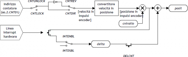
1.2.2 Operations with counting
You can lock and unlock the updating with CNTLOCK andCNTUNLOCK commands.
You can reverse and restore the counter direction with CNTREV and CNTDIR commands.
1.2.3 Fast acquisition of counting on hardware interrupts
The INTENBL and INTDSBL commands enable and disable the interrupt line connected to the transducer's zero pulse. The value of the capture parameter defines on which this impulse will be frozen on instantaneous count; the count caught is placed in the delta parameter.
1.2.4 Delta count
| The modify of the resolution value (cntratio) or the writing of the posit variable, causes the reset of the remnants of the conversion. |
|---|
The device always shows the absolute position of the axis; the counter change can be executed alsowith the direct writing in the new value on the posit paramenter.
Wanting to steal 100 units of measure to the count you can:
Axis:posit = Axis:posit - 100
This introduces an error because it imposes the location “posit = -100”, when the axis could have an intermediate position between a unit of measurement and subsequent (esxample 100.3). This fraction (0.3) is lost and the repetition of these steps will the accumulation of a considerable error.
The DELCNT command sum at the count an amount equal to thedelta parameter without losing the fraction part of the position:
Axis:delta = -100
DELCNT Axis
1.2.4.1 Example
The reading of the axis is of 2 units and is located at point A. You want to add to the count posit three units of measure.
With the instructions:
Axis:posit = Axis:posit + 2
the axis takes the new B position.
With the instructions:
Axis:delta = 2
DELCNT Axis
the axis takes the C position C.
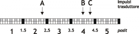
Note that with the first instructions the axis took a delta less than 3 units and then introduced an error.
If you need to send DELCNT commands in succession, It is convenient to calculate the greatness to be summed and send once the command; otherwise Beware not to send subsequent commands without a read statement on device parameter.
1.2.4.2 Example
Axis:delta = 3
DELCNT Axis
WAIT Axis:st_init
Axis:delta = 40
DELCNT Axis
1.3 Commands and parameters table
1.3.1 Symbols used
The name of the parameter, state oo command comando is shown to the left side of the table.
R
Indicates whether its parameter or state is retentive (upon initialization of the device maintains the previously state defined), or the state assumes upon initialization of the device.
If the device does not need to initialize the field “R” indicates the value that the parameter or state presenting to power up of the card.
R = Retentive
0 = Upon initialization of the device the value is forced to zero.
1 = Upon initialization of the device the value is forced to one.
- = Upon initialization of the device is presented significant value.
D
Indicates the size of the parameter.
F = Flag
B = Byte
W = Word
L = Long
S = Single Float
1.3.1.1 Conditions
Describes all of the conditions that is considered correct or because the command is accepted.
In some cases, limit values are specified for the acceptance of the parameter: if introduce any values outside the limits set, the data is still accepted; therefore appropriate controls of the application must be provided to ensure the proper functioning.
To run a command, all conditions must be met; otherwise, the command is not sent.
A
Indicates the access mode.
R = Read.
W = Write.
RW = Read / Write.
1.3.2 Commands
The commands were ranked by decreasing priority. For example, in the case of contemporary of CNTLOCK andCNTUNLOCK commands, is acquired first the CNTLOCK command.
| Name | Conditions | Description |
|---|---|---|
| CNTLOCK | st_init = 1 | Counter lock Blocks the acquisition of axis count even if the transducer continues to send signals. At this stage the possible displacement of the axis is not detected. Activates the st_cntlock state. |
| CNTUNLOCK | st_init = 1 | Counter unlock Unlock the axis count. Is rehabilitated the updating of the count. Disable the st_cntlock state. |
| CNTREV | st_init = 1 | Counter reverse Invert the phases of the transducer inside the card. Is then reversed the direction of the count (increase/decrease). Activates the st_cntrev state. |
| CNTDIR | st_init = 1 | Counter direct The axis counting is not reversed. Disable the st_cntrev state. |
| INTENBL | st_init = 1 capture>0 1£ IntL £ 8 | Interrupt enable Enable capture of the count that will be stored in delta. Activates the st_intenbl state. |
| INTDSBL | st_init = 1 | Interrupt disable Disable the count capture. Disable the st_intenbl state. |
| RSCAPTURE | st_init = 1 | Reset capture Disable the st_capture state. |
| DELCNT | st_init = 1 st_intenbl = 0 | Delta counter The count (axis position) is changed by adding algebraically the value specified in the delta parameter (posit = posit + delta). |
1.3.3 Parameters
| Name | D | R | A | Conditions | Description |
|---|---|---|---|---|---|
| cntratio | L | R | R-W | No | Counter ratio Defines how the transducer pulses must be multiplied so that the acquisition of movements is expressed in the unit of measure desired. By setting 100000 the count variation is 1 bit per pulse transducer. Valid range: 374 ÷ 400000 |
| posit | L | R | R-W | No | Actual position Is the value of the instantaneous position of the axis. Value expressed in units of measurement (Um). Valid range: -999999 ÷ 999999 |
| delta | L | R | R-W | No | Delta counter Is the value that is added to the count when sending a DELCNT command. Value expressed in units of measurement (Um). Valid range: -999999 ÷ 999999. |
| capture | B | R | R-W | No | Capture mode Defines how to count is captured on hardware interrupts. 0 = Disable. 1 = Single capture on falling edge. 2 = Single capture on the rising edge. N.B. The capture of the counting is enabled if the state st_intenbl = 1. |
1.3.4 Status
| Name | D | R | A | Conditions | Description |
|---|---|---|---|---|---|
| st_cntlock | F | R | R | No | Counter locked Counting signaling axis is blocked. 0 = Axis count unlocked. 1 = Axis count blocked. |
| st_cntrev | F | R | R | No | Counter reversed Inverted axis count report. 0 = Axis count not inverted. 1 = Inverted axis count. |
| st_intenbl | F | 0 | R | No | Interrupt enabled Reports enabling the capture of the count from hardware interrupt line. Is activated by the INTENBL command and disabled from INTDSBL command. Is automatically disabled to capture occurred. 0 = Capture of the count is not enabled. 1 = Capture of count enabled. |
| st_capture | F | 0 | R | No | Counter capture Is activated at the capture of the count; is reset from the RSCAPTURE command. 0 = The capture of the count does not executed. 1 = The capture of the count executed. |
1.4 Limitations
If you change the cntratio parameter After sending the DELCNT command, are cleared the remnants of the conversion of the “delta space” in pulses.
1.5 Application example
1.5.1 Configuration file
;*************************************************************************************
; Module Name: Ex_Count.CNF                         Project: Ex_COUNT
; Author: QEM srl                                   Date : 01/05/99
; System: QMove1 / QCL3                             Library: 1LIB3B04
; Functionality: CPUNTER managing example           Release: 0
;------------------------------------- Note ------------------------------------------
; [1] - Sample application to use the COUNTER 2 device
;*************************************************************************************

;-------------------------------------------------------------------------------------
; Defining Constants
;-------------------------------------------------------------------------------------
CONST

;-------------------------------------------------------------------------------------
; SYSTEM Variables Definition
;-------------------------------------------------------------------------------------
SYSTEM
slPrsPos  L                               ;Preset quota
slSet1    L                               ;Setpoint 1
slSet2    L                               ;Setpoint 2

;-------------------------------------------------------------------------------------
; GLOBAL Variables Definition
;-------------------------------------------------------------------------------------
GLOBAL

;-------------------------------------------------------------------------------------
; TIMER Variables Definition
;-------------------------------------------------------------------------------------
TIMER

;-------------------------------------------------------------------------------------
; DATAGROUP Definition
;-------------------------------------------------------------------------------------
;DATAGROUP

;-------------------------------------------------------------------------------------
; Bus Configuration
;-------------------------------------------------------------------------------------
BUS
    1   1CPUB   02
    2   1MIXA   00
    3   .
    4   .

;-------------------------------------------------------------------------------------
; INPUT Variables Definition
;-------------------------------------------------------------------------------------
INPUT
ifAbilZ     F    2.INP01                 ;Enabling capture zero pulse
ifAxeFermo  F    2.INP02                 ;Signaling axis stopped

;-------------------------------------------------------------------------------------
; OUTPUT Variables Definition
;-------------------------------------------------------------------------------------
OUTPUT
ofGTSet1    F    2.OUT01                 ;Reporting setpoint 1 is exceeded ->
ofLTSet2    F    2.OUT02                 ;Reporting setpoint 2 is exceeded <-

;-------------------------------------------------------------------------------------
; Internal Device Declaration
;-------------------------------------------------------------------------------------
INTDEVICE
;Name  Typo     TCamp   Counter   Inter
Axis   COUNTER2 2       2.CNT01     1

END
1.5.2 COUNTER2 management
;*************************************************************************************
; File Name  : TASK_00.MOD
; Project    : EX_COUNT
; Description: Positioning Control
;*************************************************************************************

;-------------------------------------------------------------------------------------
; Initialization work Axis
;-------------------------------------------------------------------------------------
Axis:cntratio = 100000                          ;Encoder resolution = Space in 1 round
                                                ;encoder(Um) / encoder pulse round
Axis:capture = 1
IF slSet1 EQ 0
  slSet1 = 500
ENDIF
IF slSet2 EQ 0
  slSet2 = 100
ENDIF

;-------------------------------------------------------------------------------------
; Preset search enabled at each step the limit switch
; ------------------------------- variables used -------------------------------------
; slPrsPos : Preset quota set
;--------------------------------------------------------------------------------------
MAIN:
  IF ifAbilZ                                    ;Waits for the enable input
                                                ;zero pulse transducer
    INTENBL Axis                                ;Enables the capture of zero-pulse
                                                ;transducer
  ELSE
    INTDSBL Axis                                ;Disable the zero pulse
                                                ;transducer capture
  ENDIF

IF Axis:st_capture                              ;If the count is captured
  IF ifAxeFermo                                 ;If the axis is stopped
    Axis:delta = -(Axis:delta-slPrsPos)         ;Dimension calculation from sum to count
    DELCNT Axis                                 ;Imposed on the new value of the reference count
    RSCAPTURE Axis                              ;Reset the axis's st_capture
  ENDIF
ENDIF

;-------------------------------------------------------------------------------------
; Comparisons on counting
; ----------------------------- variables used --------------------------------
; slSet1: Comparison quota for ofGTSet1 output
; slSet1: Comparison quota for ofLTSet2 output
;-------------------------------------------------------------------------------------
IF Axis:posit GT slSet1                         ;If the count is > of setpoint 1
  SETOUT ofGTSet1                               ;Activates the ofGTSet1 output
ELSE
  RESOUT ofGTSet1                               ;Disable the ofGTSet1 output
ENDIF
IF Axis:posit LT slSet2                         ;If the count is < of setpoint 2
  SETOUT ofLTSet2                               ;Activates the ofLTSet2 output
ELSE
  RESOUT ofLTSet2                               ;Disable the ofLTSet2 output
ENDIF

;-------------------------------------------------------------------------------------
; Final operations
;-------------------------------------------------------------------------------------
  WAIT 1
  JUMP MAIN

END