This is an old revision of the document!
DEVICE HEAD2
0.1 Introduction
The HEAD2 device manages the control of heads for sanders, grinders and milling machines working material flowing along a conveyor belt. You can simultaneously handle up to 8 heads, individually configurable working, using various setup parameters.
An important feature is the ability to set of fixes related to the operation of the heads, in order to compensate for any delays to answer machine. These corrections are calculated taking into account the speed of the belt.
0.2 Installation
0.2.1 Device declaration in the configuration file (.CNF)
In the configuration unit, the INTDEVICE section must be declared so that you have the hardware resources necessary for the use of the HEAD2 device. Must be add the following definition:
;---------------------------------
; Internal device declaration
;---------------------------------
INTDEVICE
<device_name> HEAD2 TCamp ICont inp01 inp02 inp03 out1 out2 out3 out4 out5 out6 out7 out8
0.2.1.1 Description of fields:
where:
| <device_name>: | the name assigned to the device |
| HEAD2: | keyword that identifies the heads device controller |
| TCamp: | sample time device (1÷125 ms) |
| ICont: | address bi-directional counter input |
| inp01: | address piece presence input |
| inp02: | address of the first phase correction input |
| inp03: | address of the second phase correction input |
| out1÷8: | address of the digital outputs of the head command |
 | ATTENTION: It is necessary that each definition are present on the same line. In case you do not want to assign a resource, for example inp02, you must enter in the appropriate field the string X.X. |
|---|
0.3 Operation
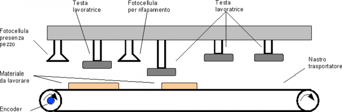
The HEAD2 device allows you to simultaneously handle up to 8 working heads, that can be individually configured, using the setup parameters, how planing, milling or grinding machines. The device allows you to make, during processing, corrections of workloads to compensate for delays in response of the machine. These corrections will be made taking into account the tape drive speed so you can automatically compensate for workloads according to variations of the speed.
The system consists of a bi-directional transducer (typically an encoder) bound to the material on the conveyor belt and a maximum of three fixed presence sensors piece that allow acquisition and correction, for the entire length of the conveyor belt, for the image of the pieces introduced.
In the case of use of heads as edging, in the program you can set after how many meters you will have to activate the lowering of the head for wear compensation. In the case of use of heads as sanders, in the correction data you can set the delay quota descent heads early slab and the proportion of early ascent of relative to the end plate. When using milling heads, in data processing, you can set the delay to the start of the quota from the beginning milling and length of the slab milling.
The card allows maximum 30 working contemporary pieces.
0.3.1 Calculation of belt speed
By receiving impulses from a bi-directional transducer (typically an encoder mounted on the motor shaft that moves the conveyor belt) the device can calculate the speed of movement in the desired unit (properly setting measure, pulse, unitvel and decpt).
The device counts the number of pulses received over a period of time defined by the tbf parameter and then calculates the speed in that time interval. The possibility of programming this parameter allows you to have greater accuracy depending on the speed of the tape. For example, at very low speeds we can't set a sampling time too high, in this case, the device would have a hard time calculating the speed.
0.3.2 Sanding
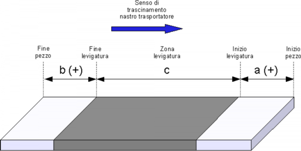
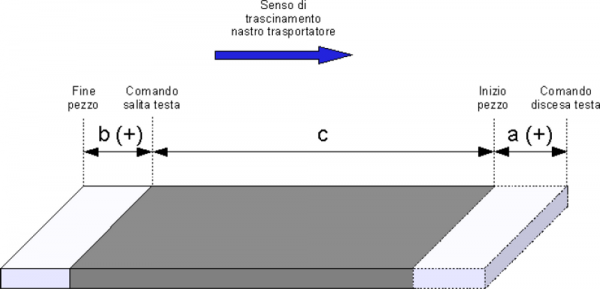
Configuring a head as sander, it's possible that works the material only “in the center”, by this we mean that you can delay your descent or anticipate the ascent of each individual head using the downhone and risehone parameters.
The data entered in these parameters can take positive or negative values.
In case you set positive values the piece will be work as per drawing below; the quota is equal to the value set in the downhone parameter, the b quota is equal to the value set in the risehone parameter while the c quota is the space in which the head works effectively.
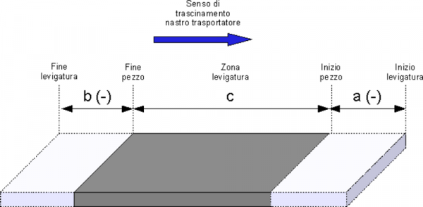
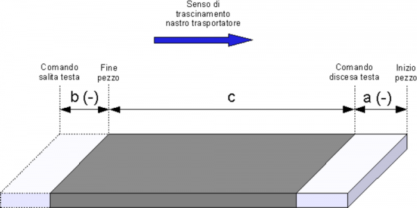
In case you set negative values the piece will be work as per drawing below; the a quota is equal to the value set in the downhone parameter, the b quota is equal to the value set in the risehone parameter.
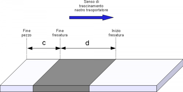
0.3.3 Milling
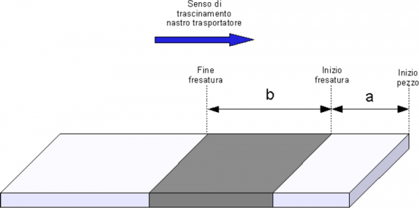
When using a head as miller you may decide to work for a given length (lengthmill) at some distance from the beginning or the end of the piece.
To run the cable working with respect to the beginning of the piece, you should set the parameter risemill = -1 and the piece will be worked as per drawing below; the a quota is equal to the value set in the downmill parameter, while the b quota is equal to the value set in the lengthmill parameter.
To run the cable working with respect to the end of the workpiece, you must set the parameter downmill = -1 and the piece will be worked as per drawing below; the c quota is equal to the value set in the risemill parameter, while the d quota is equal to the value set in the lengthmill parameter.
In the case of use of heads as sander or milling machine, You can anticipate the descent or ascent of each individual head depending on the speed of the conveyor belt using the downlag1,2,3 and riseadv1,2,3 parameters. The data entered in these parameters can take positive or negative values. In case you set positive values and the ribbon is advancing at the speed set, in corrvel1,2,3 the piece will be worked as per drawing below; the a quota is equal to the value set in the downlag1,2,3 parameter while the b quota is equal to the value set in the riseadv1,2,3 parameter.
In the case where negative values are set the piece will be worked as per drawing below; the a quota is equal to the value set in the downlag1,2,3, parameter while the b quota is equal to the value set in the riseadv1,2,3 parameter.
There are also two parameters (actriseadv and actdownlag) that lets you know the current correction value applied to a given head.
0.3.3.1 Added value of fixes
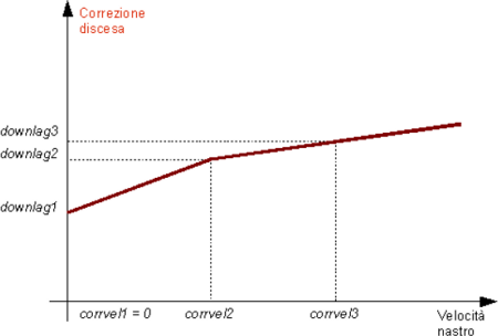
It is made so you can create a feature lead and lag correction depending on the speed of the tape. Were determined three linearization points (corrvel1, corrvel2 and corrvel3), each of these corresponds a clear lead and lag correction (riseadv1,2,3 and downlag1,2,3). For the speed of the tape contained within the linearization points, is treated as correction value, the straight line joining the two end points of linearization. An example is shown in the following figure.
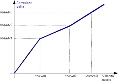
The feature will go always to the origin except in cases where corrvel1 is set equal to 0: in this case, the downlag1 value (or riseadv1) will be to consider how to fix at zero speed (that is an offset). An example is shown in picture.
0.3.4 Cancellation
Suppose that while working a piece broke, you must lock the machine to remove the piece from tape.
To restart the machine, the heads about that piece will continue to fall, creating serious problems to the functionality of the machine.
To work around this problem, You can delete a single item from the chain of working, using the CLPIECE command.
0.3.5 Using multiple devices in series or in parallel
In case the machine to be programmed to have a particular configuration, you can use more than one device. Declaring two devices, with the same address for input piece detection and with distance sensor-heads properly configured, you can manage a machine which has more than eight heads.
If you declare two devices with different sensors for detecting piece, they can manage a machine with two parallel production lines.
0.3.6 Notes on operation of the device
Lists some notes on operation of the device:
-
the correction value for offsetI01 is calculated every 250 ms, correction values for heads are calculated every 2 s,
-
the device does not support the operation with a “infinity piece”: the REGOFF command leave the control outputs to QCL, which can develop these and other features,
-
because of the different ways to reset (see the resettype parameter), the list of parameters that are saved with the SaveData command is much greater than just the retentive device parameters.
0.4 Parameters table
| Name | D | R | A | Conditions | Description |
|---|---|---|---|---|---|
| measure | L | R | RW | pwork=0 | Reference measure for calculating the conversion factor between primary impulses and units of measure Indicates the space, in units of measurement, the conveyor path to get primary impulses set in pulse parameter. This parameter is used to calculate the conversion factor between primary impulses and units of measure. posit = encoder * measure / pulse The relationship measure/pulse must be a value between 0.00935 and 1. Valid range: 1÷999999 Unit of measure: Um |
| pulse | L | R | RW | pwork=0 | Number of impulses for calculating the conversion factor between primary impulses and units of measure Indicates the number of impulses that produces the bi-directional transducer integral with the conveyor belt, to get a measure of movement. This parameter is used to calculate the conversion factor between primary impulses and units of measure. posit = encoder * measure / pulse The relationship measure/pulse must be a value between 0.00935 and 1. Valid range: 1÷999999 |
| unitvel | B | R | RW | pwork=0 | The time unit for the speed calculation Defines the unit of measurement of the speed of the conveyor belt: 0 = Um/min 1 = Um/sec Valid range: 0÷1 |
| decpt | B | R | RW | pwork=0 | Selecting the speed unit The unit of measurement of conveyor belt speed depends on the unitvel e decpt parameters. Through decpt you determine whether to set the speed in multiples of the fundamental units of measure Um. For example, if the fundamental unit of measure Um = mm, and unitvel = 1, you get the speed indicator in the vel variable in: - mm/s (con decpt = 0) - cm/s (con decpt = 1) - dm/s (con decpt = 2) - m/s (con decpt = 3) Valid range: 0÷3 |
| disti02 | L | R | RW | pwork=0 | Distance between the sensor and the first piece rephasing sensor Defines the distance (expressed in Um) between the sensor of piece presence INP01 and the correction sensor piece INP02. If that parameter is set to 0, the signal from correction sensor piece INP02 it is not considered. Valid range: 0÷999999 Unit of measure: Um |
| disti03 | L | R | RW | pwork=0 | Distance between the sensor and the first piece rephasing sensor Defines the distance (expressed in Um) between the sensor of piece presence INP01 and the correction sensor piece INP03. If that parameter is set to 0, the signal from correction sensor piece INP03 it is not considered. Valid range: 0÷999999 Unit of measure: Um |
| zvelen | B | R | RW | pwork=0 | Operation heads with tape below the threshold of zero speed Determines the operation of the heads in case the belt speed from dropping below the threshold of zero speed (settable with zvel parameter): 0 = When the machine falls below a threshold of zero velocity heads remain in position 1 = When the machine falls below a threshold of zero speed all heads are raised and fall again when the machine restarts and the speed exceeds the threshold set Valid range: 0÷1 Unit of measure: Um |
| zvel | L | R | RW | pwork=0 | Zero speed threshold Indicates the speed in Uv below which the device considers the machine at standstill. Valid range: 0÷999999 Unit of measure: Uv |
| dvelf | L | R | RW | pwork=0 | Filter activation threshold Indicates the threshold speed variations (in a sample time expressed by the tbf parameter), expressed in Uv, within which is placed the filter for speed reading. Valid range: 0÷999999 Unit of measure: Uv |
| tfilter | W | R | RW | pwork=0 | The filter time constant Indicates the time constant of the filter applied to the speed. Valid range: 0÷9999 Unit of measure: ms |
| tbf | B | R | RW | - | Sample time of the frequency counter 0 = 240 ms 1 = 480 ms 2 = 24 ms 3 = 120 ms 4 = 960 ms 5 = 1200 ms The device, to calculate the frequency of the input signals to the bi-directional meter (frq parameter), count the number of pulses received over a period of time defined by the tbf parameter and calculates an average value. The smaller is the sampling time, more faster the update of the frq parameter, but you have to be careful at low frequencies, because the sample time may not be long enough to collect samples. Valid range: 0÷5 |
| testinp | B | R | RW | pwork=0 | Minimum time of acquiring the piece presence variation inputs The card check the state of the status and fix piece inputs (INP01, INP02 and INP03) each sampling time of the device. This parameter indicates the number of seconds of sampling should be logical state, so that the device will aquires the change. With the value 0 is done one test. Valid range: 0÷127 |
| resettype | B | R | RW | pwork=0 | Powering down hardware operation This parameter is used to choose the behavior of the device when you turn off the hardware: 0 = workpiece dimensions are stored and retained in memory even after switch off 1 = the device at the time of restart will reset all information related to the pieces in progress. Valid range: 0÷1 |
| beltlength | L | R | RW | pwork=0 | Conveyor belt length Defines the distance (expressed in Um) between the piece presence sensor 1 and the end of the machine. When a piece is located inside this length the blower stays on (st_blower = 1). Valid range: 0÷999999 Unit of measure: Um |
| offseti01 | L | R | RW | pwork=0 | Advance/delay end piece This parameter defines the difference (expressed in Um) the switching point between the rising and lowering of the input of presence piece. In practice the input value allows you to anticipate (positive value) or delay (negative value) the end of the piece than the falling edge of the input piece presence. Valid range: -999÷999 Unit of measure: Um |
| grtime | L | R | RW | pwork=0 | Tape length Defines the time, expressed in hundredths of a second, to enable heads configured as grinder, when reaching the preset set in program data. Valid range: 0÷6000 Unit of measure: 1/100 sec |
| zvelp | B | R | RW | pwork=0 | Enabling acquisition piece at zero speed This parameter is used to select whether the machine captures the incoming pieces although the belt speed is below the threshold of zero speed: 0 = even when the conveyor belt speed is less than the value entered for the zvel parameter, captures all state changes (activations/deactivations) of the input of presence piece INP01 1 = when the conveyor belt speed is less than the value entered in the zvel parameter, input is not captured the disable of the input presence piece INP01 Valid range: 0÷1 |
| distp | L | R | RW | pwork=0 | Minimum distance pieces When two pieces are closer than that programmed in this parameter, are considered a single piece for the purposes of processing. The number of workpieces (pworked parameter) instead always counts 2 separate pieces. This parameter is used only by heads configured as sanders. Valid range: 0÷9999 Unit of measure: Um |
| corrvel1 | L | R | RW | pwork=0 | Speed corresponding to the point P1 of the linearization straight Defines the speed of the tape to the point P1 of the linearization straight. Valid range: 0÷999999 Unit of measure: Uv In the case that corrvel1 is set to 0 the riseadv1 and downlag1 values will be considered as a correction to zero speed (that is an offset) |
| corrvel2 | L | R | RW | pwork=0 | Speed corresponding to point P2 of linearization straight Defines the speed of the tape to the point P2 of the linearization straight. Valid range: 0÷999999 Unit of measure: Uv |
| corrvel3 | L | R | RW | pwork=0 | Speed corresponding to point P3 of linearization straight Defines the speed of the tape to the point P3 of the linearization straight. Valid range: 0÷999999 Unit of measure: Uv |
| mworked | L | R | RW | - | Um worked by machine Indicates the number of Um of material processed by the machine. The value is calculated by adding the length of pieces recorded by the sensor. Valid range: 0÷999999 Unit of measure: Um |
| pworked | L | R | RW | - | Pieces worked by the machine Indicates the number of pieces worked by machine. Valid range: 0÷999999 Unit of measure: Um |
| pwork | B | R | R | - | Pieces of work in progress Indicates the number of pieces of work in progress in the machine. Valid range: 0÷30 |
| heads | B | R | R | - | Heads state Indicates the state of the heads, is the decimal number conversion to bit fields where the 0 indicates the head lifted and 1 the lowered head. Valid range: -32767÷32768 |
| frq | L | 0 | R | - | Input signal frequency Is the frequency value of the input signals to the bidirectional counter. The update is done with sampling time selected using tbf parameter. Unit of measure: Hz |
| lengthp | L | 0 | R | - | Length last piece acquired Indicates the length in Um the last piece acquired by the sensor piece present. Unit of measure: Um |
| posit | L | R | RW | - | Current position in units of measurement Is the value of the instantaneous position of the conveyor belt. The value is automatically reset to zero when the piece presence sensor (INP01) detects a piece. To the deactivation of the input, the position changes according to the value of the offsetI01 parameter. Valid range: -999999÷999999 Unit of measure: Um |
| encoder | L | R | RW | - | Current position in primary pulses Is the value of the instantaneous position of the conveyor expressed in primary pulses. The value is automatically reset to zero when the piece presence sensor (INP01) detect a piece. To disable the input itself the position changes according to the value of the offsetI01 parameter. Valid range: -999999÷999999 Unit of measure: Um |
| vel | L | 0 | R | - | Conveyor belt speed Is the value of the instantaneous speed of the conveyor belt. The update is performed with sampling time set by tbf. The speed unit depends on the unitvel and decpt parameters. Unit of measure: Uv |
| headin | B | - | RW | - | Number head on which to store data Indicates the number of the head on which to store the data entered when is given a WRITESET/WRITEPRG command or read with the READSET/READPRG command. Valid range: 1÷8 |
| headout | B | - | RW | - | Number head on which have been read or written data Indicates that the data written head were stored or the data from the read head are available. To verify that the command sent (WRITESET/WRITEPRG or READSET/READPRG) has been executed, you should check that headin = headout. Valid range: 1÷8 |
| piecein | B | - | RW | - | Indicates the number of the part to be deleted Indicates the number of the part to be deleted using the CLPIECE command. Valid range: 1÷31 |
| pieceout | B | - | RW | - | Indicates the number of the part that was deleted Indicates, when equals to piecein, the piece selected was deleted by the CLPIECE command. Valid range: 1÷31 |
| errcode | B | 0 | R | - | Error identification code Indicates the type of error intervened in the system. When st_error is equal to 1, are present on the errcode variable what kind of error occurred (see the table) and in the errvalue variable an indication as to the cause of error. To clear the st_error status you have to send the RSERR command. Valid range: 0÷100 |
| errvalue | B | 0 | R | - | Identifying code off error cause Indicates the cause of the error in the system. The code is valid only if st_error = 1. Valid range: 0÷100 |
| wrncode | B | 0 | R | - | Identification code warning Indicates the last warning occurred in the device management commands: Code 1 = Attempt to write access on a parameter when the conditions weren't met Code 2 = Attempt to execute a command when the conditions weren't met Valid range: 0÷3 |
| wrnvalue | B | 0 | R | - | Identification code of the cause of the warning Indicates the cause of the warning in the system. Valid range: 0÷100 |
| seti01 | L | R | RW | pwork=0 | Generic parameter Parameter available for future implementations. |
| seti02 | L | R | RW | pwork=0 | Generic parameter Parameter available for future implementations. |
| seti03 | L | R | RW | pwork=0 | Generic parameter Parameter available for future implementations. |
0.4.1 Parameters managed with READSET and WRITESET
| Name | D | R | A | Conditions | Description |
|---|---|---|---|---|---|
| dist | L | R | RW | - | Sensor distance beginning piece - head This parameter indicates the distance between the sensor and the head piece indicated in the headin parameter. Valid range: 1÷999999 Unit of measure: Um |
| mode | B | R | RW | - | Way of working of the head Way of working of the head indicated in the headin parameter: 0 = head nor present 1 = sander head 2 = milling head 3 = grinding head 4 = head sander disabled 5 = milling head disabled 6 = grinder head disabled Valid range: 0÷6 N.B.: You can disable the single head with pieces in the car using the WRITESET command and change only the mode parameter. To disable it you must switch from current to the corresponding mode disabled. Different writings are not accepted by this. |
| riseadv1 | L | R | RW | - | Advance of hill head - point 1 Defines the advance of the head (expressed in unit of measure) indicates in headin compared to the end of the piece in case the conveyor blet is moving at corrvel1 speed. This correction is related to the point P1 of linearization. It is used only if the read head in headin is configured as milling or sander. Valid range: -9999÷9999 Unit of measure: Um |
| riseadv2 | L | R | RW | - | Advance of Hill head - point 2 Defines the advance of the head (expressed in unit of measure) indicates in headin compared to the end of the piece in case the conveyor blet is moving at corrvel2 speed. This correction is related to the point P2 of linearization. It is used only if the read head in headin is configured as milling or sander. Valid range: -9999÷9999 Unit of measure: Um |
| riseadv3 | L | R | RW | - | Advance of Hill head - point 3 Defines the advance of the head (expressed in unit of measure) indicates in headin compared to the end of the piece in case the conveyor blet is moving at corrvel3 speed. This correction is related to the point P3 of linearization. It is used only if the read head in headin is configured as milling or sander. Valid range: -9999÷9999 Unit of measure: Um |
| downlag1 | L | R | RW | - | Head-down delay - point 1 Defines the delay in lowering of the head (expressed in unit of measure) indicates in headin compared to the beginning of the piece in case the conveyor blet is moving at corrvel1 speed. This correction is related to the point P1 of linearization. It is used only if the read head in headin is configured as milling or sander. Valid range: -9999÷9999 Unit of measure: Um |
| downlag2 | L | R | RW | - | Head-down delay - point 2 Defines the delay in lowering of the head (expressed in unit of measure) indicates in headin compared to the beginning of the piece in case the conveyor blet is moving at corrvel2 speed. This correction is related to the point P2 of linearization. It is used only if the read head in headin is configured as milling or sander. Valid range: -9999÷9999 Unit of measure: Um |
| downlag3 | L | R | RW | - | Head-down delay - point 3 Defines the delay in lowering of the head (expressed in unit of measure) indicates in headin compared to the beginning of the piece in case the conveyor blet is moving at corrvel3 speed. This correction is related to the point P3 of linearization. It is used only if the read head in headin is configured as milling or sander. Valid range: -9999÷9999 Unit of measure: Um |
0.4.2 Parametri gestiti con READPRG e WRITEPRG
| Nome | D | R | A | Condizioni | Descrizione |
|---|---|---|---|---|---|
| downhone | L | R | RW | - | Ritardo discesa testa per levigatrice Definisce il ritardo discesa testa indicata in headin (espresso in unità di misura) rispetto all'inizio del pezzo nel caso in cui la testa indicata in headin sia programmata come levigatrice. Range valido: -999999÷999999 Unità di misura: Um |
| risehone | L | R | RW | - | Anticipo salita testa per levigatrice Definisce l'anticipo salita testa indicata in headin (espresso in unità di misura) rispetto alla fine del pezzo nel caso in cui la testa indicata in headin sia programmata come levigatrice. Range valido: -999999÷999999 Unità di misura: Um |
| downmill | L | R | RW | - | Distanza inizio pezzo - inizio fresatura Definisce la distanza (espressa in Um) tra l'inizio del pezzo e l'inizio della fresatura della testa nel caso in cui la testa indicata in headin sia programmata come fresatrice. Se si vuole programmare la lunghezza della fresatura con la testa indicata in headin rispetto alla fine del pezzo bisogna impostare questo parametro a -1. Range valido: -1÷999999 Unità di misura: Um |
| risemill | L | R | RW | - | Distanza fine pezzo - fine fresatura Definisce la distanza (espressa in Um) tra la fine del pezzo e la fine della fresatura della testa nel caso in cui la testa indicata in headin sia programmata come fresatrice. Se si vuole programmare la lunghezza della fresatura con la testa indicata in headin rispetto all'inizio del pezzo bisogna impostare questo parametro a -1. Range valido: -1÷999999 Unità di misura: Um |
| lengthmill | L | R | RW | - | Lunghezza fresatura Definisce la lunghezza (espressa in Um) della fresatura eseguita con la testa indicata in headin nel caso in cui la testa indicata in headin sia programmata come fresatrice. Range valido: 0÷999999 Unità di misura: Um |
| grlength | L | R | RW | - | Limite compensazione usura molatrice Definisce dopo quante Um si attiva l'elettrovalvola della testa relativa, per compensare l'usura della mola nel caso in cui la testa indicata in headin sia stata configurata come testa molatrice. Range valido: 0÷999999 Unità di misura: Um |
0.4.3 Parametri gestiti con READVAR e WRITEVAR
| Nome | D | R | A | Condizioni | Descrizione |
|---|---|---|---|---|---|
| hworked | L | R | RW | - | Um lavorati dalla testa Indica il numero di Um di materiale lavorati dalla testa. Tale dato viene aggiornato solamente per lo spazio effettivo che la testa lavora. Range valido: 0÷999999 Unità di misura: Um |
| actriseadv | L | R | RW | - | Correzione attuale apportata alla salita della testa Indica, in Um, il valore attuale della correzione apportata alla salita della testa. Unità di misura: Um |
| actdownlag | L | R | R | - | Correzione attuale apportata alla discesa della testa Indica, in Um, il valore attuale della correzione apportata alla discesa della testa. Unità di misura: Um |
| actpiece | B | R | R | - | Numero pezzo in lavorazione Indica il numero del pezzo in lavorazione. |
0.4.4 Parametri gestiti con READPIECE
| Nome | D | R | A | Condizioni | Descrizione |
|---|---|---|---|---|---|
| pcstart | L | - | R | - | Distanza inizio pezzo dal sensore 1 Indica la distanza dell'inizio del pezzo dal sensore I01. Unità di misura: Um |
| pcend | L | - | R | - | Distanza fine pezzo dal sensore 1 Indica la distanza della fine del pezzo dal sensore I01. Unità di misura: Um |
| pcstate | L | - | R | - | Stato del pezzo Indica lo stato di lavorazione del pezzo: 0 = normale 1 = il pezzo è stato cancellato con il comando CLPIECE Range valido: 0÷1 |
0.5 Elenco stati
| Nome | Valore di default | Descrizione |
|---|---|---|
| st_init | 0 | Stato di inizializzazione Segnalazione di device inizializzato: 0 = device non inizializzato 1 = device inizializzato |
| st_inp0X | 0 | Stato dell'ingresso INP0X Segnala lo stato dell'ingresso INP0X (dove X=1÷3): 0 = ingresso disattivo 1 = ingresso attivo |
| st_out0X | 0 | Stato dell'uscita OUT0X Segnala lo stato dell'uscita OUT0X (dove X=1÷8): 0 = uscita disattiva 1 = uscita attiva |
| st_reset | 0 | Stato del nastro Segnalazione di nastro in reset: 0 = nastro non in reset 1 = nastro in reset Questa segnalazione si attiva a seguito di un comando di reset lavorazione (con comando dedicato o con comando INIT se resettype = 1) e rimane attiva finché il nastro non ha percorso uno spazio pari all'interasse maggiore tra tutte le teste abilitate. |
| st_blower | 0 | Stato soffiatore Segnalazione di soffiatore attivo. Si attiva solamente se è presente almeno un pezzo nella lunghezza macchina: 0 = soffiatore non attivo 1 = soffiatore attivo |
| st_ovrmxp | 0 | Raggiungimento limite massimo pezzi in macchina Segnalazione di raggiungimento del limite massimo pezzi in macchina: 0 = funzionamento regolare, 1 = raggiunto il numero massimo pezzi. Questa segnalazione rimane attiva sempre per almeno 500ms. |
| st_cntlock | R | Stato di aggiornamento posizione disabilitato Segnalazione di aggiornamento posizione bloccato: 0 = aggiornamento posizione abilitato 1 = aggiornamento posizione disabilitato |
| st_cntrev | R | Stato di inversione aggiornamento posizione Segnalazione di aggiornamento posizione invertito: 0 = aggiornamento posizione non invertito 1 = aggiornamento posizione invertito |
| st_regoff | 0 | Disattivazione aggiornamento uscite Stato che segnala se l'aggiornamento delle uscite è disabilitato 0 = la regolazione è attivata 1 = la regolazione è disattivata |
| st_error | 0 | Presenza di un errore Indica lo stato di errore del device. Per riconoscere il tipo di errore si deve far riferimento alle variabili errcode ed errvalue: 0 = errore non presente 1 = errore presente |
| st_warning | 0 | Presenza di un warning Indica lo stato di warning del device, per riconoscere il tipo di warning si deve far riferimento alle variabili wrncode e wrnalue: 0 = warning non presente 1 = warning presente |
0.6 Tabella comandi
Tutti i comandi (generici, nastro e memoria programmi) sono da intendersi in ordine di priorità, indipendentemente dalla tabella nella quale sono stati inseriti.
0.6.1 Comandi generici
| Nome | Condizione | Descrizione |
|---|---|---|
| INIT | - | Inizializzazione del device Comando di inizializzazione del device. Prima del comando INIT è possibile scrivere tutti i parametri nel device senza richiedere ricalcoli interni, perciò la scrittura sarà molto veloce. Attiva lo stato st_init. |
| RSERR | st_error=1 | Reset dello stato di errore Azzera lo stato st_error. |
| RSWRN | st_warning=1 | Reset dello stato di warning Azzera lo stato st_warning. |
| SETINP0X | INP0X dichiarato come X.X | Attivazione INP0X Comando che simula un fronte di attivazione dell'ingresso INP0X (dove X = 1÷3). |
| CLRINP0X | INP0X dichiarato come X.X | Disattivazione INP0X Comando che simula un fronte di disattivazione dell'ingresso INP0X (dove X = 1÷3). |
| CNTLOCK | - | Disabilita l'aggiornamento della posizione attuale del nastro Disabilita l'aggiornamento della posizione attuale. In questa situazione l'eventuale spostamento del nastro non viene rilevato. |
| CNTUNLOCK | - | Abilita l'aggiornamento della posizione attuale del nastro Abilita l'aggiornamento della posizione attuale del nastro. Viene attivata la rilevazione dello spostamento del nastro. |
| CNTDIR | - | Aggiornamento posizione nastro non invertita Disabilita una eventuale inversione dell'aggiornamento posizione; lo stato st_cntrev è posto a zero. |
| CNTREV | - | Inversione dell'aggiornamento posizione nastro Consente di invertire il segno dell'aggiornamento posizione. |
| CLPIECE | - | Elimina pezzo Elimina il pezzo selezionato dalla variabile piecein. Se piecein = -1, viene resettata l'immagine dei pezzi all'interno del nastro trasportatore. |
| REGOFF | - | Disabilitazione dell'intervento del device Disabilita la regolazione e l'aggiornamento delle uscite. |
| REGON | - | Abilitazione dell'intervento del device Riabilita la regolazione e l'aggiornamento delle uscite. |
0.6.2 Comandi gestione memoria programmi
| Nome | Condizione | Descrizione |
|---|---|---|
| READSET | st_init=1 headin>=1 headin⇐8 | Lettura parametri di setup Consente la lettura dei parametri di setup della testa headin. A comando concluso headout = headin. |
| WRITESET | pwork=0 headin>=1 headin⇐8 | Scrittura parametri di setup Consente la scrittura dei parametri di setup della testa headin. A comando concluso headout = headin. in fase di scrittura dei parametri di lavoro viene resettato l'eventuale stato di soffiatore attivo (st_blower = 1). Nel caso questa azione possa portare a problemi è necessario eseguire il comando solo se: NOT <nome_device>:st_blower AND <nome_device>:pwork EQ 0 |
| READPRG | st_init=1 headin>=1 headin⇐8 | Lettura programma Consente la lettura dei programmi di lavoro selezionati da headin. A comando concluso headout = headin. |
| WRITEPRG | st_init=1 headin>=1 headin⇐8 | Scrittura programma Consente la scrittura dei programmi di lavoro selezionati da headin. A comando concluso headout = headin. in fase di scrittura dei parametri di setup viene resettato l'eventuale stato di soffiatore attivo (st_blower = 1). Nel caso questa azione possa portare a problemi è necessario eseguire il comando solo se: NOT <nome_device>:st_blower AND <nome_device>:pwork EQ 0 |
| READVAR | st_init=1 headin>=1 headin⇐8 | Lettura variabile Consente la lettura delle variabili selezionate da headin. A comando concluso headout = headin. |
| WRITEVAR | st_init=1 headin>=1 headin⇐8 | Scrittura variabile\ Consente la scrittura delle variabili selezionate da headin. A comando concluso headout = headin. |