This is an old revision of the document!
DEVICE OOPOS2
0.1 Introduction
-
The OOPOS2 device can control the location of an axis moved basically from digital controls of forward, backward and slow; the location of the axis is acquired via a bi-directional transducer.
-
The movement commands can be sent directly to the motor in AC via contactors, or be sent to an inverter.
-
The OOPOS2 device includes all functions necessary for the implementation of ON/OFF placements, in addition to special functions such as automatic recalculation of inertia, the mechanical backlash recovery management, managing the slowdown is proportional to the speed and a complete search of presets to synchronize the actual position of the axis with the internal value of the device.
0.2 Installation
0.2.1 DEVICE DECLARATION IN THE CONFIGURATION FILE (.CNF)
In the configuration file (.CNF), the BUS section must be declared so that you have the hardware resources required for the implementation of the OOPOS2 device.
There must be at least a bi-directional meter. The device can also use an interrupt input and a line for preset search functions.
In the INTDEVICE section of the .CNF file must be add the following definition:
;---------------------------------
; Internal device declaration
;---------------------------------
INTDEVICE
<device name> OOPOS2 TCamp IQCTL ILine IAZero OutAva OutInd OutDir OutMov OutRal OutFre
 | It is necessary that each definition are present on the same line. In case you do not want to assign a resource, for example OutFre, You must always enter in the appropriate field the string X.X. |
|---|
where:
| <nome device> | The name assigned to the device. |
| OOPOS2 | Keyword that identifies the on/off positioner device. |
| TCamp | Sampling time device (1÷255 ms). |
| IQCTL | Bidirectional incremental counter address. |
| ILine | Interrupt line dedicated to the zero pulse. |
| IAZero | Input to enable the capture of zero-pulse. |
| OutAva | Address of output used as forward output. |
| OutInd | Address of output used as backward output. |
| OutDir | Address of output used as direction output. |
| OutMov | Address of output used as motion output. |
| OutRal | Address of output used as slowdown output. |
| OutFre | Address of output used as brake output. |
0.2.1.1 Example
;--------------------------------
; Internale device declaration
;--------------------------------
INTDEVICE
Axis OOPOS2 0004 2.CNT01 1 2.IN01 2.OUT01 2.OUT02 X.X X.X 2.OUT3 X.X
0.3 GETTING STARTED ON ON/OFF POSITIONING
The digital outputs for managing the placement are enable/disable depending on the position of the axis (counter), appropriately controlled by the device depending on the parameterization.
The ON/OFF positioning can executed in both directions (forward/backward) with the possibility of retrieving games, for deletion of any mechanical backlash.
0.3.1 Retrieving backlash
The accuracy with which was built the mechanics is critical to the outcome of the placements. It is impossible to find, on the placements, the precision of the motion of bodies if the moving parts have loose backlash of the tenth. Also on placements of vertical axes very heavy (for example a press or vertical cutter), the inertia of movement upwards is less than the inertia of movement down.
In these and other situations implementation of recovery backlash in positioning significantly improves accuracy.
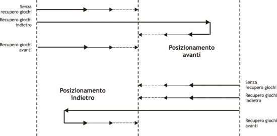
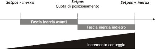
| The positioning is always concluded in the same direction. For example, whereas placements with recovery forward backlash (see Picture 1), for both forward and reverse positioning, the movement of the axle ends always moving from left to right (forward). |
|---|
| Picture 1: positioning diagram with recovery backlash. |
 |
0.3.2 FORWARD POSITIONING WITHOUT RECOVERY BACKLASH
In the Picture 2 Describes the various stages of a ON/OFF placement forward without the implementation of recovery backlash.
The excitement of moving outputs (in this casa the forward output) moving the axis; increasing the count acquired and the appropriate device parameters involve the activation of several resignations to motion management, up to the end of placement and the activation of tolerance output (positioning report concluded correctly).
| Picture 2: forward positioning without the recovery backlash. |
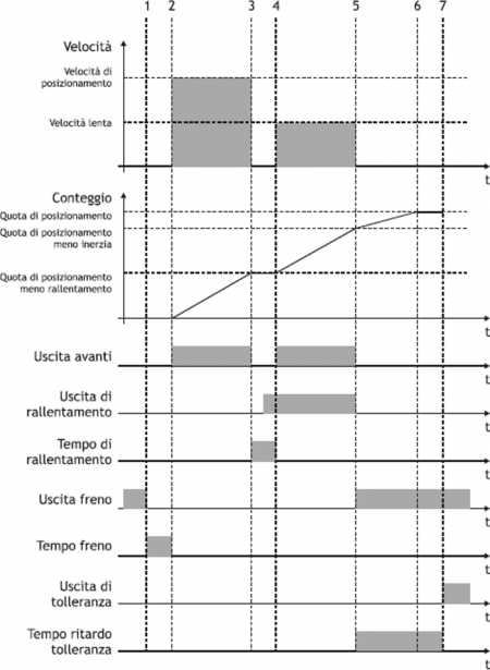 |
0.3.2.1 Initial conditions
-
The axis is stopped (st_still = 1).
-
The count is reset to zero (posit = 0).
-
All outputs are disable (with the exception of brake output).
-
You have set both the share placement (setpos) that the slowdown quota (slowpos).
0.3.2.2 Phase 1
-
The OOPOS3 device receives the command of START positioning.
-
Brake output disabled (st_brake = 0).
-
The advance brake output timer is set to the value defined in the tbrake parameter.
0.3.2.3 Phase 2
-
Terminates the advance brake output timer.
-
It's enabled the forward output (st_movfwd = 1).
-
The axis begins the movement (vel) and the counter (posit) increases.
-
After an acceleration ramp (defined from mechanical inertia or in any acceleration values set in the inverter), axis speed is constant.
0.3.2.4 Phase 3
-
Positioning reaches the deceleration range (setpos - slowpos).
-
The forward output is disable (st_movfwd = 0).
-
The slowdown timer is set to the value defined by the parameter slowdly.
-
When the timer of slowdown is half the value set, activates the slowdown output (st_movslow = 1): This is to avoid problems with special switches-mechanical devices.
0.3.2.5 Phase 4
-
Ends the slowdown timer.
-
Is enabled the forward output (st_movfwd = 1).
-
The axis moving with slow speed.
0.3.2.6 Phase 5
-
The placement reached the inertial range (setpos - iner[ninert]).
-
The forward (st_movfwd = 0) and slowdown (st_movslow = 0) outputs are disabled.
-
The delay timer tolerance is set to the toldly value and start counting.
-
The axis keeps moving because of its inertia (variable according to its weight, speed, friction).
0.3.2.7 Phase 6
-
The axis stops.
-
It is important that the axle ends the movement before the end of the timer to delay tolerance.
0.3.2.8 Phase 7
-
Terminates the delay tolerance timer.
-
Brake output is enabled (st_brake = 1).
-
If enabled, runs the recalculation of inertia.
-
If the placement ends in tolerance, is enable the out of tolerance (st_toll =1).
0.3.3 FORWARD POSITIONING WITH RECOVERY BACKLASH IN BACKWARD DIRECTION
In the Picture 3 describes the various stages of a ON/OFF forward placement with the implementation of recovery backlash in backward direction.
The activation of (forward / backward) outputs moving the axis; the increasing of the count acquired and the appropriate device parameters involve the activation of other outputs to the motion management, up to the end of placement and activation of the output of tolerance (positioning report concluded correctly).
| Picture 3: forward positioning with backward recovery backlash. |
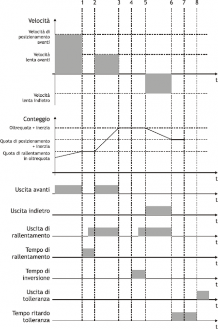 |
0.3.3.1 Premise
For complete understanding of this description you should have read the previous paragraph (FORWARD POSITIONING WITHOUT RECOVERY BACKLASH).
0.3.3.2 Initial conditions
-
The axis moves at the speed of positioning.
-
Count greater than zero.
-
All disable outputs except the forward output.
0.3.3.3 Phase 1
-
The count reaches the deceleration range for recovery overquota backlash (setpos + overpos - slowpos).
-
The forward output is disabled (st_movfwd = 0).
-
The slowdown is set to the value of the slowdly parameter.
0.3.3.4 Phase 2
-
Terminates the timer advance unlock brake.
-
It's enabled the forward output (st_movfwd = 1).
0.3.3.5 Phase 3
-
Terminates the slowdown timer.
-
It's enabled the forward output (st_movfwd = 1).
-
The axis moves at low speed.
0.3.3.6 Phase 4
-
Positioning reaches the inertial range (setpos + overpos + iner[ninert]).
-
The forward (st_movfwd = 0) and slodown (st_movslow = 0) outputs is disabled.
-
The reverse timer is set to the value of tinv.
0.3.3.7 Phase 5
-
Terminates the reverse timer.
-
The placement resumes in the backward direction.
0.3.3.8 Phases 6÷8
-
Normal positioning phases as described above.
0.4 Operation
0.4.1 HARDWARE CONNECTION
The OOPOS3 device needs some necessary hardware resources, as a bidirectional counter input (CNTxx) and the digital outputs.
0.4.2 CHECK THE OPERATION OF THE COUNTER RESOURCE
The following procedure is used to test the counter input.
-
Initialize the device axis with INIT command.
INIT Axis -
Checking if the st_init state activation.
WAIT Axis:st_init -
Enter the value 100000 in the cntratio parameter.
Axis:cntratio = 100000 -
Reset the value of posit parameter.
Axis:posit = 0 -
Move forward one revolution axis turning the encoder: verify that the value of the Axis:posit variable it's positive and matches the number of pulses/Rev encoder.
-
If the Axis:posit value is negative, swap the encoder phases.
If the Axis:posit value remains to zero, check the electrical connections.
0.4.3 CHECK THE OPERATION OF THE DIGITAL OUTPUTS
| Before moving the axis, check the proper operation of emergency equipment and protection. |
|---|
The following procedure is used to verify the operation of the digital outputs of forward, backward and slowdown moving the axis with the manual commands of the device.
To continue, verify that the Axis device is initialized and with the correct Asse:cntratio value.
-
Set the maximum value the software limits of the device in order to enable its movement. Insert the 999999 value in the maxpos parameter and the -999999 in the minpos parameter.
Axis:maxpos = 999999
Axis:minpos = -999999 -
Give the MANFFW command to active only the forward output..
MANFFW Axis -
To verify the correct execution of the command, check that the st_still state is to 0 and st_movfwd is to 1:
WAIT NOT Axis:st_still AND Axis:st_movfwd -
Check that the axis moves forward and that the count showed in
Axis:positit increments, then stop the movement with the STOP command.
STOP Axis -
If the forward output, for example is correspondent to the 2.OUT01 resource, don't enable, check the electrical connection.
-
Dare il comando MANFBW per eccitare la sola uscita d'Indietro.
MANFBW Axis -
To verify the correct execution of the command, check that the st_still state is to 0 and st_movbwd is to 1:
WAIT NOT Axis:st_still AND Axis:movbwd
0.5 Functions
0.5.1 Multi-axis management
In some applications you are prompted to place a large number of axes by moving a single axis at a time. The choice may be to install one drive which depending on the axis to be placed electrically connects the engine interested in positioning; the transducer is always bound to its axle.
The EPICPOS parameter allows you to control access to the DAC device using the REGON and REGOFF commands. In this way through the QCL application defines a set of device many axes to be placed; in the definition, all devices use the same resource DAC (IOutA).
Normally all devices must be in the st_regoff = 1 state so you will not have access to the DAC. Before you start positioning, with the REGON command, the device is brought to the st_regoff = 0 state. It's execute the placement and to the completion, the device is returned in the st_regoff = 1 state with REGOFF command. For no reason two devices simultaneously must be found in the st_regoff = 0 state.
When the device is placed in the regoff position, the analog output remains fixed at the last voltage value defined before the REGOFF command.
0.5.2 Change quota and count in motion
| Changing the quota is accepted only if the new position is reached with the use direction and if the axis is not already in slowdown phase for to reach the quota previously set. |
|---|
In some applications you are prompted to define the target quota during placement, depending to external events to the device. With this feature you can write in the setpos parameter even with current placements.
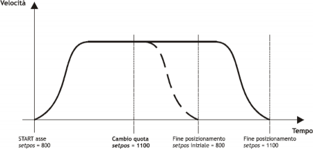
When positioning you can also change the value of the count posit. This function is usually used when a device must, under special conditions, continue a speed profile for a very long time, exceeds the time axis takes to reach the quota limit (maxpos or minpos).
-
Check that the axis moves back and that the count showed in
Axis:positdecreases, then stop the movement with the STOP command.
STOP Axis -
If the backward output Se l'uscita di Indietro, for example the resource
2.OUT02, don't enable, check the electrical connection. -
Give the MANSFW command to enable the forward and slowdown outputs.
MANSFW Axis -
To verify the correct execution of the command, check that the st_still state is to 0, st_movfwd is to 1 and st_movslow is to 1:
WAIT NOT Axis:st_still AND Axis:st_movfwd AND Axis:st_movslow -
Check that the axis from moving forward at a speed lower than the previous and that the count showed in
Axis:positis increments, then stop the movement with the STOP command.
STOP Axis -
If the slowdown output, corresponding to the
2.OUT03resource, does not turn on, check the electrical connection.
0.5.3 Axis resolution parameter setting
To Introduce the locating dimensions in desired unit (Um) You must multiply the pulses generated by the transducer for the multiplicative ratio (cntratio); this parameter must be between the values: 374 < cntratio < 400000.
Multiplicative coefficient calculation As an example, consider introducing dimensions in mm; the unit of measurement (Um) will be in mm.
If the space of 1000 mm is accomplished with 20000 pulses, the Axis:cntratio variable should be set to:
Axis:cntratio = Um x 100000 / pulse_numbers
that is:
Axis:cntratio = 1000 x 100000 / 20000 = 5000
Multiplicative value of 100000 adapt the result of dividing to the format in which is expressed the variable Axis:cntratio.
This is an integer number but expresses a value with a decimal point at the fifth significant digit. To write Axis:cntratio=100000 means setting a ratio Um/pulse_numbers equal to 1.00000.
0.5.3.1 Example
-
Enter the value 100000 in the cntratio parameter
Axis:cntratio = 100000 -
Reset the value of the posit parameter
Axis:posit = 0 -
Shift the axis of a specific space, for example 1000 mm., that call Sp.
-
Capture the value of the Axis:posit parameter
-
In Axis:cntratio introduce the integer value resulting from the formula:
Axis:cntratio = Sp * 100000 / Axis:posit
0.5.4 Basic settings
For work properly the OOPOS2 device, you must enter a few basic parameters.
-
Determining the software limits to be introduced in the maxpos and minpos parameters.
Axis:minpos = xxx(xxx = minimum axis value expressed in Um).
Axis:maxpos = yyy(yyy = maximum axis value expressed in Um). -
If you are using a two speed system, set the required space to the axis to switch from high speed to slow speed the at the enabled of the slowdown output; insert the data in the slowpos parameter.
Axis slowpos = zzz(zzz = slowdown axis value expressed in Um). -
Set the time for disable the output of movement when the shaft enters the deceleration range so that the slowdown output does not cause electrical failure or excitement; so that the output slowdown does not cause electrical failure or excitement;slowdly.
Axis:slowdly = ttt(ttt = slowdown time in s/100). -
Set the tolerance limits to be obtained when placing in the parameters tollp and tolln. As a first approach, introducing the higher values at precisions requests.
Axis:tollp = tpx(tpx = positive tolerance value expressed in Um/10).
Axis:tolln = tnx(tpn = negative tolerance value expressed in Um/10). -
Set the time axis inversion in the tinv parameter.
Axis:tinv = inversion time expressed in s/100 -
Consider a single inertia range for all axis; then, set the ninert parameter to “1”.
Axis:ninert = 1 -
Enable recalculation of inertia when the placement ends out of tolerance; then, set the inertmode parameter and “1”.
Axis:inertmode = 1 -
Set the time delay tolerance, considering the time it takes for the axis to decelerate to a stop; then, set thetoldly parameter.
Axis:toldly = tdly(tdly = activation time delay tolerance expressed in s/1000).
0.5.5 The slowdown
0.5.5.1 Introduction
In the ON/OFF placements the space of slowdown should be long enough to bring the axis at the slow speed (of end placement), which enter the inertial range and conclude your placement in tolerance. It is essential that the speed at the time of entry in the inertial range is always equal, so that inertia is repetitive and continuous recalculations are avoided that would cause an inaccuracy in positioning.
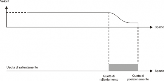
| Correct slowdown quota: before stopping the axis moves at low speed, facilitating the stop without compromising the execution time of positioning |
|---|
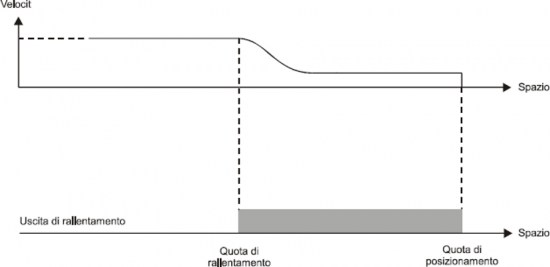
| Slowdown quota is too long: This allows the axis to end positioning by moving the slow speed, but is maintained for too much space, extending considerably the time of positioning. |
|---|
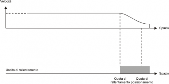
| Slowdown quota is too short: the axis approaches at the quota with a speed too high to allow the mechanical rapid stop; the succession of the system compromises the placement, stopping the axle out of the tolerance range set. |
|---|
In some cases the OOPOS3 device must manage the axis where positioning speed is variable. For this reason the OOPOS2 device has a system of automatic calculation of the slowdown quotaq, so the speed of end placement and the inertia value are repetitive, regardless of the speed of the axis and the value of inertia are repetitive, regardless of the speed of the axis..
The OOPOS2 device has two methods (selected by the slowtype parameter), to calculate the slowdown:
-
With slowtype = 1, the slowdown is calculated proportionately to the positioning speed.
-
With slowtype = 2, the slowdown is calculated according to the square of the positioning speed.
0.5.5.1.1 Setting of the speed variable
To calculate the slowdown value you need setting to acquire the axis speed.
The unit of speed is in function of the following variables:
-
unitvel
-
decpt
Unitvel parameter Defines if the speed values are expressed in Um at the minute (unitvel = 0) or in Um at the second (unitvel = 1).
Decpt parameter Whether to set the values of speed in multiples of the fundamental units Um. For example, if the fundamental unit of measure Um=mm, and unitvel=1 you get the speed indicator in the vel variable:
-
with decpt = 0 in mm/s
-
with decpt = 1 in cm/s
-
whit decpt = 2 in dm/s
-
whit decpt = 3 in m/s
0.5.5.1.2 Maximum speed calculating
Theoretical method
you have to apply the formula:
Speed = Frequency * ….
Pratical method It's based on the speed reading detected by the device in the vel parameter giving the drive a known voltage. If driving permits, provide the maximum working voltage axis and then read the value in the vel parameter; if you provided a lower voltage, the maximum speed will be proportional to the voltage supplied.
Enter the value of the maximum speed detected in maxvel parameter.
0.5.5.2 Proportional to the speed slowdown
The device calculates the slowdown based on the formula:
Slowdown = (Maximum slowdown x Speed)/Maximum speed
| The calculation of the slowdown, as evidenced by the chart, one of the two maxslow or minslow limits cannot exceed. |
|---|
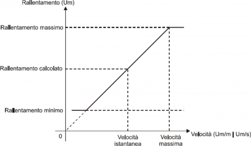
where:
Maximum slowdown = corresponds to the maxslow variable.
Minimum slowdown = corresponds to the minslow variable.
Calculated slowdown = corresponds to the exeslow variable.
Maximum speed = corresponds to the maxvel variable.
Instantaneous speed = corresponds to the vel variable.
0.5.5.2.1 Proportional slowdown to the square of the speed
The device auto-calculates the slowdown based on the formula:
Slowdown = (Maximum slowdown x Speed2)/Maximum speed
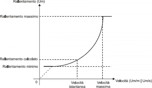
where:
Maximum slowdown = corresponds to the maxslow variable.
Minimum slowdown = corresponds to the minslow variable.
Calculated slowdown = corresponds to the exeslow variable.
Maximim speed = corresponds to the maxvel variable.
Instantaneous speed = corresponds to the vel variable.
0.5.6 RECALCULATION OF INERTIA
The values of inertia can be introduced directly by the operator or automatically calculated from the device; the mode is chosen with setting the inertmode parameter.
The device manage the subdivision of the axis path (between the minpos and maxpos) in more same bands; the number of bands is defined by the ninert parameter. This way you can have inertia as a function of the band within which concludes the positioning.
By setting the dobiner = 0 parameter, the device manage a unique inertia value independently of direction of movement (forward or backward).
By setting the dobiner = 1 parameter, the device manage two inertia values for each band, one for the forward direction and another for the backward direction. This mode is applicable, for example, when you move the vertical axis.
For storing inertia, are used the iner01÷ iner08 parameters (in the event that dobiner = 0) or the iner01÷ iner16 parameters (if dobiner = 1):
| dobiner = 0 | dobiner = 1 | |
|---|---|---|
| iner01 | Inertia 1 band | Forward intertia 1 band |
| iner02 | Inertia 2 band | Backward intertia 1 band |
| iner03 | Inertia 3 band | Forward intertia 2 band |
| iner04 | Inertia 4 band | Backward intertia 2 band |
| iner05 | Inertia 5 band | Forward intertia 3 band |
| iner06 | Inertia 6 band | Backward intertia 3 band |
| iner07 | Inertia 7 band | Forward intertia 4 band |
| iner08 | Inertia 8 band | Backward intertia 4 band |
| iner09 | n.u. | Forward intertia 5 band |
| iner10 | n.u. | Backward intertia 5 band |
| iner11 | n.u. | Forward intertia 6 band |
| iner12 | n.u. | Backward intertia 6 band |
| iner13 | n.u. | Forward intertia 7 band |
| iner14 | n.u. | Backward intertia 7 band |
| iner15 | n.u. | Forward intertia 8 band |
| iner16 | n.u. | Backward intertia 8 band |
By definition, the forward inertia is used only forward in movements (forward output enabled) while, the backward inertia, is used only for backward movements (backward output enabled).
0.5.7 Managing Automatic recalculation Inertia
The calculation of inertias about the various bands can be done automatically by the device; at the end of each placement, the device quantify the value of inertia for use in subsequent placements that will end in the same band.
You can define a set of customizations related to automatic recalculation of inertia.
0.5.7.1 Inertmode
With the setting of this parameter is used to define when the device execute the recalculating of inertia; there are two methods:
-
The recalculation is executed only if the placement ends outside the tolerance range.
-
The recalculation is executed at the end of each placement, although it ended in or out of the tolerance range.
0.5.7.2 Toldly
-
Automatic recalculation of inertia is executed by OOPOS2 device when ended the activation delay tolerance (toldly), at the end of which the axis is considered definitely in stop.
0.5.7.3 Maxiner
-
If the value of the inertia recalculated diverges beyond a certain value from inertia in use, you can have an alert (st_erin = 1 state); this alert may in any case be disabled.
0.5.8 The preset search
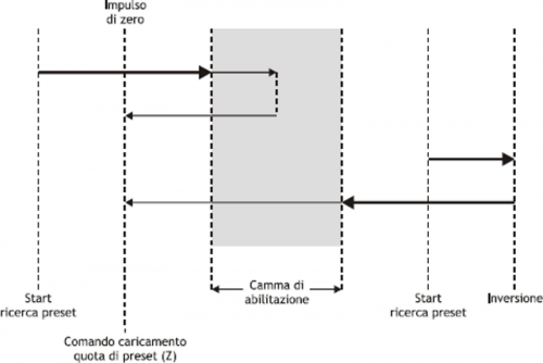
The preset searchb is a procedure to synchronize the value of the posit parameter with the actual position of the axis. Consists to load a value in the counter (previously stored) at the time of acquisition of transducer zero pulse; you can execute the preset search with a transducer without the zero pulse, but you need an input (cam or sensor) by 'enabling zero-pulse transducer'.
Formerly to the preset search the counter acquired can have any value and the axis can be located anywhere. For execute the upload of preset quota, the axis you must direct to the “enabling zero-pulse transducer” input.
The initial direction of motion is defined by prsdir parameter:
prsdir = 0 the axis will start getting forward.
prsdir = 1 the axis will start getting backward.
| During the preset search the software the maxpos and minpos limits are disabled. |
|---|
The preset search start is given from the PRESET command.
If during the preset search is given again the PRESET command, the direction of motion of the axis is reversed, preserving the operation of the preset search direction.
It should be noted that the presets quota (prspos) must always be between the minimum and maximum quotas and after the load of the preset quota, the axis is automatically positioned to the preset quota.
0.5.8.1 Mode 0: loading presets with moving procedure
| The zero pulse enable input has a hardware filter which delays the acquisition and so influence the precision of the loading. Axis speed should be low enough to allow the acquisition of the input. |
|---|
The axis towards to the sensor connected to the enable input zero pulse with a normal placement speed. The st_prson state reports that the preset procedure is in progress. When, during the path, the axis bump into the enabling zero-pulse transducer input, reverses the direction and takes slow speed.
To the disabling of enabling zero-pulse transducer input is loaded the preset quota on the counter (posit parameter).
The axis stop, the st_prson state is disabled and the st_prsok state is aenabled to signal the end of search. This State remains active until the starting of a new presets procedure. When the system is power up this state is always to zero (Picture 1).
| Picture1: preset load using the only enabling cam. |
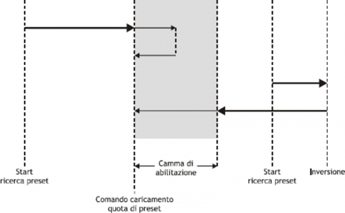 |
0.5.8.2 Mode 1: preset load with moving procedure
| The acquisition is execute on interrupt input then the speed of the axis is not determinative. However, you must verify that the zero pulse activation time is long enough to be captured by the card. |
|---|
The axis towards the sensor connected to input enabling zero-pulse with normal positioning speed. The st_prson state reports that the preset procedure is in progress. When, during the path, the axis mbump into the enabling zero pulse transducer input, reverses the direction and takes the slow speed.
To disable the zero pulse enable input is enabled the reading of the first zero-pulse provided by the transducer and at the time of the acquisition of this signal, is loaded the preset quota in the counter (posit parameter).
The axis stops, the st_prson state is disabled and the st_prsok state is enabled to signal the end of search. This state remains active until the starting of a new procedure of presets. When the system is power up this State is always zero (Picture 2).
| Picture 2: loading presets using cam and zero pulse enable transducer. |
 |
0.5.8.3 Mode 2: loading with stopped axis
With this procedure the preset search is not enabled. The command to load the preset quota is provided by the activation of the zero pulse enable input and is enabled the st_prsok state.
-
If the input remains active the loading is continuous.
-
If the input is already active to the power on the first load is executed only after its disabled.
0.5.9 Delta count
| The command can be sent only if the axis is stopped, condition of st_still = 1. |
|---|
The device always shows the absolute position of the axis; to execute the incremental placements it is necessary to have a tool to subtract or add some value to the count (posit) without introducing errors. The change counter can be execute even with a direct writing to the new value in the posit parameter.
Wanting to steal 100 units of measure from the count you can:
Axis:posit = Axis:posit - 100
| The Changing of the value resolution (cntratio) or write to the posit variable, causes the reset of the remnants of the conversion. |
|---|
This operation introduces an error because it imposes the location “posit = -100”, when the axis could have an intermediate position between a unit of measurement and subsequent (example 100.3). This fraction (0.3) is lost and the repetition of these steps results in the accumulation of a considerable error.
The DELCNT command sum to the count an amount equal to the delta parameter without losing the fraction part of the position:
Axis:delta = -100
DELCNT Axis
The DELCNT command can be sent only with stationary axis (st_still=1)
0.5.9.1 Example
The reading of the position of the axis is of 2 units and is located at point A. To sum the count posit three units.
With instructions:
Axis:posit = Axis:posit + 2
the axis takes the new position B.
With instructions:
Axis:delta = 2
DELCNT Axis
It's reached the point C.
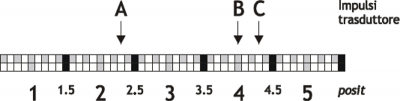
Note that with the first instructions the axis took a delta less than 3 units and then introduced an error.
If you need to send the succession of DELCNT commands, It is convenient to calculate the quantity to be summed and send at once the command; otherwise beware not to send subsequent commands without a read statement on device parameter.
0.5.9.2 Example
Axis:delta = 3 DELCNT Axis WAIT Axis:st_init Axis:delta = 40 DELCNT Axis
A writing of the type:
Axis:posit = 1000
Axis:delta = - 100
DELCNT Axis
DELCNT Axis
...
Does not ensure that the posit value is 800, as you would expect from two consecutive subtraction, while it's possible is 900 for the overlap of the two commands. The writing becomes then:
Axisposit = 1000
Axis:delta = - 100
DELCNT Axis
WAIT Axis:st_init
DELCNT Axis
WAIT Axis:st_init
...
0.5.9.3 REGON and REGOFF commands
With the OOPOS3 device address the movement outputs are for the exclusive use of the device; so they can't be used by other device or by the application.
The REGOFF command allows you to make available these resources, by disabling the update from the OOPOS3 device. This condition, verified by the st_regoff = 1 state, places the device in a pending state that still continues to update the position of the axis (acquired counting).
The REGON command restores normal conditions giving the device updating outputs.
| To avoid conflicts and malfunctions, must necessarily be active one device for each group of outputs of movement. |
|---|
In the applications that do not need to move the multiple axes, use of REGON/REGOFF controls allows you to use the same motion outputs saving hardware resources.
0.5.10 Moving
The procedures described here were allowed to complete the steps necessary to device hardware resource definition, electrical verification, of fundamental device parameters setting.
Now you can run simple movement of the axis.
-
Move the axis in a position whereby it can fulfill a certain area without meeting the quota limit.
-
Reset the count (posit = 0 parameter).
-
Set the placement quota (setpos parameter).
Axis:setpos = positioning quota(in Um between minpos and maxpos). -
tart positioning (START command).
START Axis -
To stop the positioning use the STOP command.
0.6 Special functions
0.6.1 QPS Positioning system (QEM POSITIONING SYSTEM)
| This system allows, If the resolution of the transducer allows it, adjust and check the position of the On/Off type with a resolution 10 times greater than the set. |
|---|
The introduction of inertia parameters (iner01 ÷ iner16), the tolerances (tolp and toln) and thickness tool (tool), is proposed with an addition digit, so you can introduce the data with an accuracy 10 times greater.
For a good operation of the QPS system, the cntratio parameter should be less than 40000; if the multiplicative coefficient is between 40001 and 399999 the influence of the last digit will decrease gradually up to cease completely when this coefficient is equal to 400000.
The QPS system is also introduced in the reading of the data described above.
0.6.1.1 Examples
| The examples are based on a system of positioning with millimetre precision. |
|---|
-
If a placement fee equal to 10 mm is normally inserted with the number 10, to introduce the same tolerance value (then with the QPS), you must enter the value 100.
-
A tolerance of 10 mm will be displayed with the number 100.
0.7 Commands and parameters table
0.7.1 Symbols used
The parameter name, state or command are is shown on the left side of the table.
R
Indicates if the parameter or state is retentive (upon initialization of the device maintains the previously defined state), or the state assumes upon initialization of the device.
If the device does not need to initialize the “R” field indicates the value that the parameter or state take to the power up of the card.
R = Retentive
0 = Upon initialization of the device the value is forced to zero.
1 = Upon initialization of the device the value is forced to one.
- = Upon initialization of the device is presented significant value.
D
Indicates the size of the parameter.
F = Flag
B = Byte
W = Word
L = Long
S = Single Float
0.7.1.1 Conditions
Describes all the conditions that must exist is considered correct or because the command is accepted.
In some cases, limit values are specified for the acceptance of the parameter: If are introduced any values outside the limits set, the data is however accepted; therefore appropriate controls of the application must be provided to ensure the proper functioning.
To execution of the command, all conditions must be met; otherwise the command is not sent.
A
Indicates the access mode.
R = Read.
W = Write.
RW = Read / Write.
0.7.2 Commands
The commands were ranked by decreasing priority. For example, in the case of contemporary STOP and START commands, is acquired first theSTOP command.
| Name | Conditions | Description |
|---|---|---|
| INIT | st_init = 0 | Initialization Initializing device command. If the device is not initialized, does not execute the axis calculations and then sits idle. To power on you can download all parameters in DPR; subsequently, with the INIT command the axis will be initialized, executing the calculations only once. Activates the st_init state. |
| START | st_init = 1 st_regoff = 0 st_still = 1 | Start Controls the positioning to setpos quota and setvel speed. |
| STOP | st_init = 1 st_regoff = 0 st_emrg = 0 | Stop Stops the current axis positioning. The stop of the axis follows the deceleration ramp in use. The axis remains in reaction to space. |
| CNTLOCK | st_init = 1 | Counter lock Blocks the acquisition of axis count even if the transducer continues to send signals. At this stage the possible displacement of the axis is not detected. Disables loading of presets quota on the count. Activates the st_cntlock state. |
| CNTUNLOCK | st_init = 1 | Counter unlock Unlock the axis count. Recovered read the signals sent by the transducer and the updating count. Disable the st_cntlock state. |
| CNTREV | st_init = 1 | Counter reverse Invert the phases of the transducer into the card. It's reversed the direction of the count (increase/decrease). Activates the st_cntrev state. |
| PRESET | st_init = 1 st_regoff = 0 | Preset Start search preset axis. Start search procedure with modes set with prsmode and prsdir parameters. If the preset search is already in execution, the command executes the reverse search. Activates the st_prson state and disable the st_prsok state |
| MANSFW | st_init = 1 st_regoff = 0 posit < maxpos | Manual slow forward Manual slow positioning forward. Activates the forward and slowdown outputs. |
| MANSBW | st_init = 1 st_regoff = 0 posit > minpos | Manual slow backward Manual slow positioning backward. Activates the backward and slowdown outputs. |
| MANFFW | st_init = 1 st_regoff = 0 posit < maxpos | Manual forward Manual positioning forward. Activates the forward output. |
| MANFBW | st_init = 1 st_regoff = 0 posit > minpos | Manual backward Manual positioning backward. Activates the backward output. |
| REGON | st_init = 1 | Regulation ON Enable adjustment and updating of movement outputs, and all the movement commands. Disable the st_regoff state. |
| REGOFF | st_init = 1 | Regulation OFF Disable adjustment and updating of movement outputs, and all the movement commands. Only the brake output continues to be updated. Activates the st_regoff state. |
| DELCNT | st_init = 1 st_still = 0 | Delta counter This command is accepted only if the axis is stopped; the counter (axis position) is modify by adding algebraically the value specified in the delta variable. |
0.7.3 Parameters
| Name | D | R | A | Conditions | Description |
|---|---|---|---|---|---|
| cntratio | L | R | R-W | No | Counter ratio Defines how the transducer pulses must be multiplied so that the acquisition of movements is expressed in the unit of measure desired. If setting 100000, the count variation is 1 bit for pulse transducer. Valid range: 347 ÷ 400000 |
| posit | L | R | R-W | st_init = ON | Actual position Is the value of the instantaneous position of the axis in units defined by the cntratio parameter. Value expressed in units of measurement (Um). Valid range: -999999 ÷ 999999 |
| minpos | L | R | R-W | No | Minimum position Defines the minimum quota to reach from the axis; the set value is considered as the lower limit for the introduction of quotas work. Value expressed in units of measurement (Um). Valid range: -999999 ÷ 999999 |
| maxpos | L | R | R-W | No | Maximum position Defines the maximum quota reached by the axis; the set value is to be considered also as an upper limit for the introduction of quotas of work. Value expressed in units of measurement (Um). Valid range: -999999 ÷ 999999 |
| slowpos | W | R | R-W | No | Slow position Is the distance from the positioning quota which is axtivates the slowdown output. Value expressed in units of measurement (Um). Valid range: 0 ÷ 9999 |
| tollp | W | R | R-W | Nessuna | Positive tolerance Is the positive tolerance limit allowed to positioning (maximum error for excess). It is expressed as Um/10 (QPS). Valid range: 0 ÷ 9999 |
| tolln | W | R | R-W | Nessuna | Negative tolerance Is the negative tolerance limit allowed to positioning (maximum error by defect). It is expressed as Um/10 (QPS). Valid range: 0 ÷ 9999 |
| tinv | W | R | R-W | Nessuna | Direction inversion delay Viene utilizzato per evitare stress meccanici dovuti a troppo rapide inversioni del senso di movimento. Il valore introdotto è espresso in centesimi di secondo. Viene utilizzato per evitare stress meccanici dovuti a troppo rapide inversioni del senso di movimento. Il valore introdotto è espresso in centesimi di secondo.Range valido: 0 ÷ 999 |
| slowdly | W | R | R-W | Nessuna | Slow delay Quando il posizionamento entra nella fascia di rallentamento, l'uscita di movimento viene disattivata per un tempo determinato dal parametro slowpos. L'uscita di rallentamento viene attivata con tempo slowpos/2 prima dell'uscita di movimento. Viene espresso in centesimi di secondo (s/100). Range valido: 0 ÷ 999 |
| tbrake | W | R | R-W | Nessuna | Brake time È il tempo che intercorre, allo start posizionamento, tra lo sblocco del freno (in funzione del parametro breaktype) e l'attivazione delle uscite di movimento. Viene espresso in centesimi di secondo (s/100). Range valido: 0 ÷ 999 |
| overpos | W | R | R-W | Nessuna | Over position Oltrequota per il recupero giochi e/o delta minimo di posizionamento. Se impostato a zero non viene eseguito il recupero giochi. Valore espresso in unità di misura (Um). Range valido: 0 ÷ 9999 |
| bklashmode | B | R | R-W | Nessuna | Backslash mode Seleziona il tipo di recupero giochi: 0=posizionamento senza recupero giochi. 1=posizionamento con recupero giochi avanti. 2=posizionamento con recupero giochi indietro. 3=posizionamento con recupero giochi avanti senza rallentamento. 4=posizionamento con recupero giochi indietro senza rallentamento. Se il parametro è fuori dai limiti ammessi, utilizza per default il modo 0. |
| ninert | B | R | R-W | Nessuna | Inertia number È il numero di fasce d'inerzia in cui si vuole suddividere l'asse. Se viene impostato il valore zero, si considera una sola fascia. Range valido: 1 ÷ 8 |
| maxiner | W | R | R-W | Nessuna | Maximum inertia È il massimo valore di variazione dell'inerzia dopo ogni posizionamento. Se il valore calcolato supera tale parametro, viene segnalato con l'attivazione dello stato st_erin. Se il valore viene posto a zero, il controllo è inibito. Viene espresso in Um/10 (QPS). Range valido: 0 ÷ 9999 |
| toldly | W | R | R-W | Nessuna | Tolerance delay Definisce il tempo che intercorre tra l'arrivo dell'asse nella fascia di tolleranza e la relativa segnalazione di stato. Il valore introdotto è espresso in centesimi di secondo. Range valido: 0 ÷ 9999 |
| inertmode | B | R | R-W | Nessuna | Inertia mode selection Indica il tipo di ricalcolo inerzia eseguito dal device al termine del posizionamento: 0=ricalcolo inerzie disabilitato. 1 = ricalcolo inerzie eseguito solo se il posizionamento si conclude fuori tolleranza. 2=ricalcolo inerzie eseguito ad ogni posizionamento. |
| tool | L | R | R-W | Nessuna | Tool thickness É il valore dello spessore utensile. Questo valore, espresso in Um/10 (QPS), viene sommato alla quota di posizionamento setpos quando viene comandato START. La quota finale dell'asse sarà quindi data da: setpos + tool Range valido: -999999 ÷ 999999 |
| setpos | L | R | R-W | Nessuna | Setted position É la quota di posizionamento impostata. Essa viene posta in esecuzione dal comando START. Se essa viene cambiata durante il posizionamento, l'asse si posziona comunque alla quota precedente. Valore espresso in unità di misura (Um). Range valido: -999999 ÷ 999999 |
| iner01÷iner16 | W | R | R-W | Nessuna | Inertia 01 ÷ 16 value Sono le 16 memorie dei valori di inerzia. Se il parametro dobiner è 0, verranno utilizzate dal device solamente le prime otto (iner01 ÷ iner08). Viene espresso in Um/10 (QPS). |
| dobiner | B | R | R-W | Nessuna | Double inertia Con questo parametro è possibile scegliere di ricalcolare un'inerzia unica per ogni fascia in cui è diviso l'asse oppure di averne due per ogni fascia: una per ogni direzione di arrivo dell'asse. 0=Memoria inerzia di fascia uguale per le due direzioni. 1=Memoria inerzia di fascia distinta per ogni direzione. |
| enstol | B | R | R-W | Nessuna | Enable start in tolerance Abilitazione start con asse in tolleranza: 0 = START in tolleranza disabilitato. Al comando di START lo stato st_sttoll viene abilitato e l'asse rimane fermo. 1 = START in tolleranza abilitato. Al comando di START l'asse esegue un riposizionamento alla quota in uso e lo stato st_sttoll viene disabilitato. |
| prsmode | B | R | R-W | Nessuna | Preset mode Definisce il tipo di ricerca di preset: 0 = Per la ricerca dell'abilitazione impulso di zero, l'asse inizia il movimento, incontra la camma di abilitazione, inverte la direzione ed in lento, sul fronte di discesa relativo al segnale di camma, carica la quota di preset. 1 = Per la ricerca dell'abilitazione impulso di zero, l'asse inizia il movimento, incontra la camma di abilitazione, inverte la direzione ed in lento acquisisce il primo impulso di zero (dopo la disattivazione del segnale di camma). 2 = Non viene attivata la procedura di ricerca preset con movimentazione dell'asse. Il conteggio viene aggiornato alla quota di preset all'attivazione dell'abilitazione impulso di zero. |
| prspos | L | R | R-W | Nessuna | Preset position Definisce il valore che viene caricato sul conteggio con la procedura di ricerca di preset. Valore espresso in unità di misura (Um). Range valido: minpos ÷ maxpos |
| prsdir | B | R | R-W | Nessuna | Preset search direction Definisce la direzione del movimento asse per la ricerca della camma di abilitazione impulso di zero. 0=L'asse esegue la ricerca in avanti, prima in rapido, poi in lento. 1=L'asse esegue la ricerca indietro, prima in rapido, poi in lento. 2= L'asse esegue la ricerca in avanti sempre in lento. 3= L'asse esegue la ricerca indietro sempre in lento. |
| actiner | B | R | R | Nessuna | Actual inertia Indica la fascia di inerzia in uso. Range valido: 0 ÷ 7 |
| delta | L | R | R-W | Nessuna | Delta counter Variabile d'uso come operando dal comando DELCNT. Valore espresso in unità di misura (Um). Range valido: -999999 ÷ 999999 |
| decpt | B | R | R-W | Nessuna | Decimal point Definisce la precisione con la quale si intendono impostare le preselezioni e visualizzare i conteggi relativamente all'asse. Range valido: 0 ÷ 3 |
| unitvel | B | R | R-W | Nessuna | Velocity unit Definisce se l'unità di tempo della velocità è espressa in minuti o secondi. 0 = Um/min 1 = Um/sec |
| frq | L | - | R | Nessuna | Actual frequency É il valore della frequenza istantanea dell'asse, considerando una fase dell'encoder. Valore espresso in Hz. |
| vel | L | - | R | Nessuna | Actual velocity É il valore della velocitá istantanea dell'asse. Il valore viene espresso in Um/s o Um/min in base al parametro unitvel e dipende anche dal parametro decpt. |
| breaktype | B | R | R-W | Nessuna | Brake type É il tipo di logica d'intervento dell'uscita freno. 0 = L'uscita viene eccitata per la frenata. 1 = L'uscita, normalmente eccitata, viene diseccitata per la frenata. Lo stato st_brake segue lo stato elettrico dell'uscita. |
| breaktype | B | R | R-W | Nessuna | Brake type É il tipo di logica d'intervento dell'uscita freno. 0 = L'uscita viene eccitata per la frenata. 1 = L'uscita, normalmente eccitata, viene diseccitata per la frenata. Lo stato st_brake segue lo stato elettrico dell'uscita. |
| slowtype | B | R | R-W | Nessuna | Slow type É il tipo di calcolo del rallentamento 0=fisso con parametro slowpos. 1=proporzionale alla velocità rilevata. 2=proporzionale al quadrato della velocità rilevata. |
| maxvel | L | R | R-W | Nessuna | Maximum velocity Definisce la massima velocità dell'asse. Il valore introdotto è nell'unità di tempo della velocità impostata unitvel. Questo parametro viene utilizzato se slowtype ? 0. |
| maxslow | W | R | R-W | Nessuna | Maximum slowdown É il valore di rallentamento calcolato alla massima velocità dell'asse definita dal parametro maxvel. Questo parametro viene utilizzato se slowtype ? 0. Valore espresso in unità di misura (Um). Range valido: 0 ÷ 9999 |
| minslow | W | R | R-W | Nessuna | Minimum slowdown É il minimo valore di rallentamento che puó essere calcolato. Questo parametro viene utilizzato se slowtype ?0. Valore espresso in unità di misura (Um). Range valido: 0 ÷ 9999 |
| exeslow | W | - | R | Nessuna | Execution slowdown Se il parametro slowtype ¹ 0 indica il valore di rallentamento calcolato dal device in funzione della velocità dell'asse. Valore espresso in unità di misura (Um). |
0.7.4 Stati
| Nome | D | R | A | Condizioni | Descrizione |
|---|---|---|---|---|---|
| st_init | F | - | R | Nessuna | Initialization Segnalazione di device inizializzato. 0 = Device non inizializzato. 1 = Device inizializzato. |
| st_cntlock | F | R | R | Nessuna | Counter locked Segnalazione di conteggio asse bloccato. 0 = Conteggio asse sbloccato. 1 = Conteggio asse bloccato |
| st_cntrev | F | R | R | Nessuna | Counter reversed Segnalazione di conteggio asse invertito 0 = Conteggio asse non invertito 1 = Conteggio asse invertito. |
| st_movfwd | F | 0 | R | Nessuna | Forward movement Segnala l'eccitazione dell'uscita di movimento avanti. 0 = Uscita avanti non eccitata. 1 = Eccitazione uscita avanti. |
| st_movbwd | F | 0 | R | Nessuna | Backward movement Segnala l'eccitazione dell'uscita di movimento indietro. 0 = Uscita indietro non eccitata. 1 = Eccitazione uscita indietro. |
| st_movslow | F | 0 | R | Nessuna | Slowdown movement Segnala l'eccitazione dell'uscita di rallentamento. 0 = Uscita rallentamento non eccitata. 1 = Eccitazione uscita rallentamento. |
| st_toll | F | 0 | R | Nessuna | Tolerance Segnalazione di asse in tolleranza rispetto alla quota posta in esecuzione dal comando di START. La segnalazione di asse in tolleranza può essere ritardata tramite il parametro toldly. 0 = Asse non in tolleranza. 1 = Asse in tolleranza. |
| st_brake | F | 0 | R | Nessuna | Brake Segnala l'eccitazione dell'uscita di freno (per l'attivazione di freni o di dispositivi di bloccaggio dell'asse). 0 = Uscita freno non eccitata. 1 = Eccitazione uscita freno. |
| st_movdir | F | 0 | R | Nessuna | Backward direction Segnalazione della direzione del movimento. 0 = Avanti 1 = Indietro. |
| st_still | F | 1 | R | Nessuna | Still Segnalazione di asse fermo. 0 = Asse in movimento. 1 = Asse fermo. |
| st_erin | F | 0 | R | Nessuna | Inertia ricalculation error Segnala un errore di ricalcolo inerzia. L'indicazione si attiva se il ricalcolo dell'inerzia fornisce un valore maggiore del parametro maxiner. 0 = Ricalcolo inerzia corretto. 1 = Ricalcolo inerzia con valori maggiori di maxiner. |
| st_sttoll | F | 0 | R | Nessuna | Start in tolerance Attivo segnala, se il parametro enstol 1 1, che é stato dato un comando di movimento e l'asse era giá in tolleranza sulla quota di traguardo. Lo stato rimane invariato fino al prossimo comando di movimento (START, MANSFW, MANFFW, MANSBW, MANFBW). 0 = Start con asse fuori tolleranza. 1 = Start con asse in tolleranza. |
| st_prsok | F | 0 | R | Nessuna | Preset ok Segnalazione di ricerca di preset asse conclusa correttamente. 0 = Ricerca di preset non ancora conclusa o non eseguita. 1 = Ricerca di preset conclusa correttamente. |
| st_prson | F | 0 | R | Nessuna | Preset Segnalazione di ricerca di preset asse in corso. 0 = Ricerca di preset non in corso. 1 = Ricerca di prest in corso. |
| st_regoff | F | 0 | R | Nessuna | Regulation off Segnala lo stato di disabilitazione delle uscite e dei comandi di posizionamento. 0 = Uscite di movimento abilitate. 1 = Uscite di movimento disabilitate. |
0.8 Limitazioni
Nessuna limitazione.
0.9 Esempio applicativo
0.9.1 File di configurazione
;*************************************************************************************
; Nome Modulo: Ex_Oopos.CNF              Progetto: Ex_OOPOS2
; Autore: QEM srl                        Data: 01/05/99
; Sistema: QMove1 / QCL3                 Libreria: 1LIB3B04
; Funzionalità: Esempio gestione OOPOS2  Release: 0
;-------------------------------------- Note -----------------------------------------
; [1] - Applicativo di esempio per utilizzo device OOPOS 2
;*************************************************************************************

;-------------------------------------------------------------------------------------
; Definizione Costanti
;-------------------------------------------------------------------------------------
CONST

;-------------------------------------------------------------------------------------
; Definizione Variabili SYSTEM
;-------------------------------------------------------------------------------------
SYSTEM
slQuotaPos     L                                ;Variabile per quota di posizionamento

;-------------------------------------------------------------------------------------
; Definizione Variabili GLOBAL
;-------------------------------------------------------------------------------------
GLOBAL
gfMovMan       F                                ;Flag segnalazione movimenti manuali in
                                                ;corso
gfMovAuto      F                                ;Flag segnalazione movimenti automatici
                                                ;in corso

;-------------------------------------------------------------------------------------
; Definizione Variabili TIMER
;-------------------------------------------------------------------------------------
TIMER

;-------------------------------------------------------------------------------------
; Definizione DATAGROUP
;-------------------------------------------------------------------------------------
;DATAGROUP

;-------------------------------------------------------------------------------------
; Configurazione Bus
;-------------------------------------------------------------------------------------
BUS
     1   1CPUB   02
     2   1MIXA   00
     3   .
     4   .

;-------------------------------------------------------------------------------------
; Definizione Variabili INPUT
;-------------------------------------------------------------------------------------
INPUT
ifAvMan   F   2.INP01                          ;Ingresso di avanti manuale
ifInMan   F   2.INP02                          ;Ingresso di indietro manuale
ifStart   F   2.INP03                          ;Ingresso di START asse
ifStop    F   2.INP04                          ;Ingresso di STOP asse

;-------------------------------------------------------------------------------------
; Definizione Variabili OUTPUT
;-------------------------------------------------------------------------------------
OUTPUT
ofToll    F   2.OUT04                          ;Uscita di tolleranza asse

;-------------------------------------------------------------------------------------
; Dichiarazione device interni
;-------------------------------------------------------------------------------------
INTDEVICE
;Nome   Tipo   TCamp  Contatore  Inter  AbilZero  OutAva  OutInd  OutDir  OutMov
Asse    OOPOS2 0004   2.CNT01    1      2.INP01   2.OUT01 2.OUT02         X.X    X.X

OutRal  OutFre
2.OUT03 X.X

END
0.9.2 Gestione OOPOS2
;-------------------------------------------------------------------------------------
; Nome File: TASK_00.MOD
; Progetto: EX_OOPOS2
; Descrizione: Gestione Posizionamento
;-------------------------------------------------------------------------------------

;-------------------------------------------------------------------------------------
; Operazioni di Inizializzazione Asse
;-------------------------------------------------------------------------------------
Asse:cntratio = 100000                          ;Risoluz.encoder = Spazio in 1 giro
                                                ;encoder(Um) / impulsi giro encoder
Asse:maxpos = 999999                            ;Quota massima
Asse:minpos = -999999                           ;Quota minima
Asse:slowpos = 100                              ;Quota di rallentamento
Asse:tollp = 10                                 ;Tolleranza positiva
Asse:tolln = 50                                 ;Tolleranza negativa
Asse:tinv = 50                                  ;Tempo di inversione
Asse:slowdly = 50                               ;Tempo di rallentamento
Asse:tbrake = 30                                ;Tempo di intervento freno
Asse:overpos = 0                                ;Oltrequota recupero giochi
Asse:bklashmode = 0                             ;Tipo recupero giochi
Asse:ninert = 1                                 ;Numero fasce di inerzia
Asse:maxiner = 100                              ;Massima inerzia ricalcolata
Asse:toldly = 50                                ;Tempo ritardo segnalazione tolleranza
Asse:inertmode = 1                              ;Tipo di ricalcolo inerzia
Asse:tool = 0                                   ;Spessore lama
Asse:dobiner = 0                                ;Abilitazione inerzie sdoppiate
                                                ;(avanti e indietro)
Asse:enstol = 0                                 ;Abilitazione START con l'asse in
                                                ;tolleranza
Asse:prsmode = 0                                ;Tipo di ricerca di preset
Asse:prspos = 0                                 ;Quota di preset
Asse:prsdir = 0                                 ;Direzione della ricerca di preset
Asse:decpt = 1                                  ;Cifre decimali
Asse:unitvel = 1                                ;Unità di tempo della velocità
Asse:breaktype = 0                              ;Logica di intervento del freno
Asse:slowtype = 0                               ;Tipo di calcolo rallentamento
Asse:maxvel = 1000                              ;Velocità massima
Asse:maxslow = 8                                ;Rallentamento calcolato massimo
Asse:minslow = 80                               ;Rallentamento calcolato minimo
INIT Asse                                       ;Inizializza il device
WAIT Asse:st_init                               ;Attendi che il device sia inizializzato
CNTUNLOCK Asse                                  ;Sblocca conteggio
WAIT NOT Asse:st_cntlock                        ;Attendi che il conteggio sia sbloccato
CNTDIR Asse                                     ;Imposta il senso del conteggio
WAIT NOT Asse:st_cntrev                         ;Attendi che sia impostato il senso del
                                                ;conteggio
REGON Asse                                      ;Abilita la regolazione
WAIT NOT Asse:st_regoff                         ;Attendi l'abilitazione alla regolazione
IF (slQuotaPos EQ 0)                            ;Nel caso in cui la quota di posizionamento
                                                ;dell'asse sia zero
  slQuotaPos = 2000                             ;Imposta una quota di posizionamento
ENDIF

;-------------------------------------------------------------------------------------
; Operazioni di Posizionamento
; ------------------------------ variabili utilizzate -------------------------------
; slQuotaPos: Variabile impostabile che rappresenta la quota di posizionamento dell'asse
; -------------------------------- flag utilizzati ----------------------------------
; gfMovMan: movimento manuale in corso
; gfMovAuto: Movimento automatico in corso
;-------------------------------------------------------------------------------------
MAIN:

;-------------------------------------------------------------------------------------
; Gestione uscite
;-------------------------------------------------------------------------------------
ofToll = Asse:st_toll                           ;Imposto l'uscita di tolleranza come lo
                                                ;stato di tolleranza

;-------------------------------------------------------------------------------------
; Gestione movimenti automatici
;-------------------------------------------------------------------------------------
IF ifStart                                      ;Attende l'ingresso di START
  IF NOT gfMovMan                               ;Controlla che non ci siano movimenti
;manuali
    IF Asse:st_still                            ;Controlla che l'asse sia fermo
      Asse:setpos = slQuotaPos                  ;Imposta la quota di posizionamento
      START Asse                                ;Esegue lo start dell'asse
      gfMovAuto = 1                             ;Segnala movimento automatico in corso
    ENDIF
  ENDIF
ENDIF
IF ifStop                                       ;Attende l'ingresso di STOP
  IF NOT Asse:st_still                          ;Controlla che l'asse NON sia fermo
    STOP Asse                                   ;Esegue lo stop dell'asse
  ENDIF
ENDIF

IF gfMovAuto                                    ;Controlla segnalazione movimento
                                                ;automatico in corso
  IF Asse:st_still                              ;Controlla che l'asse sia fermo
    gfMovAuto = 0                               ;Resetta stato di movimento Automatico
  ENDIF
ENDIF

;-------------------------------------------------------------------------------------
; Gestione movimenti manuali
;-------------------------------------------------------------------------------------
IF ifAvMan                                      ;Attende l'ingresso di movimento manuale
  IF NOT (gfMovAuto OR gfMovMan)                ;Controlla che non ci siano movimenti
;autometici o manuali
    IF Asse:st_still                            ;Controlla che l'asse sia fermo
      MANFFW Asse                               ;Avanti asse in manuale
      gfMovMan = 1                              ;Segnala movimento manuale in corso
    ENDIF
  ENDIF
ENDIF
IF ifInMan                                      ;Attende l'ingresso di movimento manuale
  IF NOT (gfMovAuto OR gfMovMan)                ;Controlla che non ci siano movimenti
                                                ;autometici o manuali
    IF Asse:st_still                            ;Controlla che l'asse sia fermo
      MANFBW Asse                               ;Avanti asse in manuale
      gfMovMan = 1                              ;Segnala movimento manuale in corso
    ENDIF
  ENDIF
ENDIF
IF gfMovMan                                     ;Se l'asse si muove in manuale
  IF NOT (ifAvMan OR ifInMan)                   ;Se gli ingressi di avanti e indietro
                                                ;manuale sono OFF
    STOP Asse                                   ;Ferma l'asse
    gfMovMan = 0                                ;Togli la segnalazione di asse in
                                                ;movimento manuale
  ENDIF
ENDIF

;-------------------------------------------------------------------------------------
; Operazioni finali
;-------------------------------------------------------------------------------------
  WAIT 1
  JUMP MAIN

END