TIMER ( On Delay )
| Function name | TIMER_010 |
|---|---|
| Function version | 1.0 |
| Function state | stable |
| Compatibility with IEC61131-3 | not compatible |
Graphic symbol :

Input / Output :
| Name | Belonging Group | Access | Types of data | Description |
|---|---|---|---|---|
| ON | Left Power Flow | Timer activation at rising edge | ||
| Reload | Normal | R , RW | F , B , W , L , S | Reload the timer when still running |
| Name | Name timer | Name of the timer in use | ||
| Preset | Normal | R , RW | B , W , L , S | Preset timer in milliseconds |
| Q | Right Power Flow | Resulting state of the elaboration function |
Description :
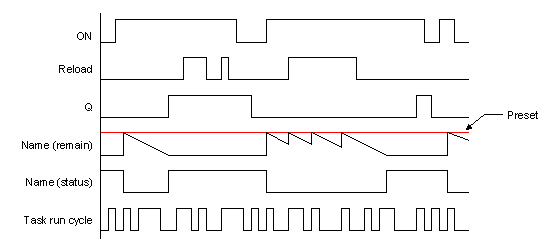
The block function TIMER provides a software timer of a specific type “on delay timer“. To work properly it needs the hardware timer of Qmove declared in the input operator Name. The function block gets the event Rising One-Shoot of the input ON to load the support hardware timer with the value defined by the input operator Preset. At this point the support hardware timer starts decreasing its value of its parameter “remain” till it reaching of the 0 (zero). The output of the on-delay timer state at the insertion Q is activated when the value of the parameter “remain” of the support hardware timer Name (Name:remain) becomes equal to 0 (zero). When the input ON is deactivated the current value of the support hardware timer is reset and the eventual output of the on-delay timer at the insertion Q set to 0 (zero). At each evaluation of the function block TIMER in which they are noticed both the input Reload activated and the support hardware timer Name in phase of running in decrement, you will have the loading of the support hardware timer Name with th value defined by the input operator Preset. In this case, if the elapsed time between an evaluation of the function block TIMER and the previous will exceed the time set in the input operator Preset you will have that the parameter “remain” of the support hardware timer will reach the value 0 (zero) without this will modify the output of the on-delay timer state Q.
Time diagram :
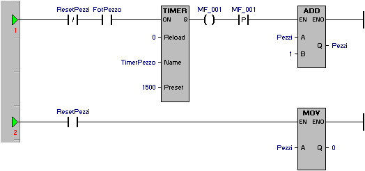
Applicative example :
In the following example it’s used the function block TIMER to get an incremental pieces-counter on activation of a photocell for at least 1,5 seconds. A second input of reset pieces will reset the counting of the pieces obtained.
Cutting of the configuration file
SYSTEM
	Pezzi	L	; Number of pieces made

GLOBAL
	MF_001	F	; Memory FLAG as support

TIMER
	TimerPezzo		; Timer for waiting to notice that a peace is made

INPUT
	; Input photocell piece
	FotPezzo	F	<numero_card>.<nome_ingresso>

	; Input reset pieces made
	ResetPezzi	F	<numero_card>.<nome_ingresso>
Cutting of the configuration file: