P1R11FE30 - 001 : Setup and Connections
Informations
Release
This document is fully valid, except for errors or omissions.
| Release | Description | Date |
|---|---|---|
| 1.0 | New manual. | 06/11/13 |
Specifications
All rights reserved on this manual. No part of this document can be copied or reproduced in any form without prior written authorisation .
QEM does not insure or guarantee its contents and explicitly declines all liability related to the guarantee of its suitability for any purpose. The information provided in this document can be changed without notice. QEM shall not be held liable for any error that may appear in this document.
Registered Trademarks:
-
QEM® is a registered trademark.
-
Microsoft® and MS-DOS® are registered trademarks and Windows® is a trademark of Microsoft Corporation.
Description
The P1R11FE30 - 001 application, installed on the Qmove J1-R11-FE30, hardware is designed to control a cookies dispensing machine with 4 axes. The salient features of the P1R11FE30 - 001 are described below.
The manual will distinguish between standard characteristics and optional. characteristics.
Overview of the Characteristics
-
Axes MMB, MMC, MCB controlled by PID on space (brushless motors with servo drives or asynchronous motors with vector inverters).
-
Axis MT for the conveyor. Only encoder simulation signal is provided.
-
Homing functions for axes MMB, MMC, MCB.
-
Select the language
-
Modbus communication with ESA hmi panel.
-
Diagnostics of the inputs and the outputs.
-
Messagges for active faults, to assist troubleshooting.
-
Help Messagges.
-
Backup and restore of the data on non volativle memory (FLASH EPROM).
Hardware and wirings
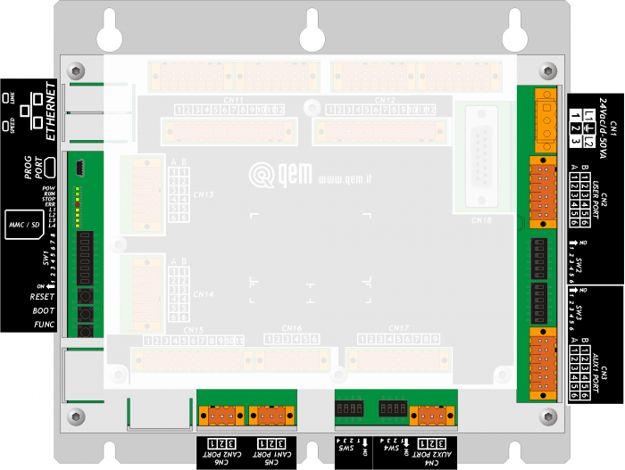
C1-R11-FE30
 |
| General view of C1-R11FE30 |
 |
| Rear view of SLOT2 of C1-R11FE30 |
 |
| Rear view of SLOT3 of C1-R11FE30 - 1MG5F card |
A1-HMI-QC050
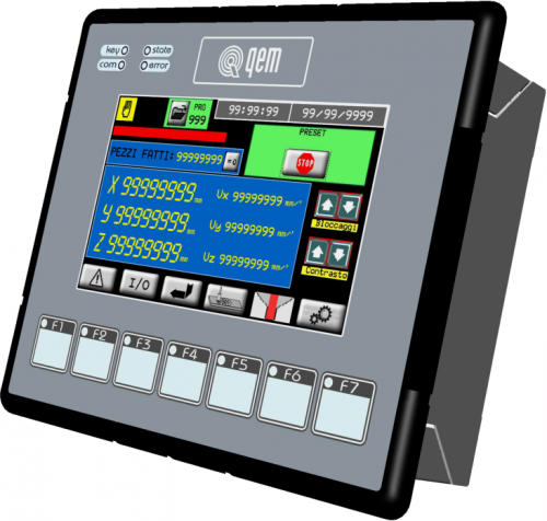 |
| General view of A1-HMI-QC050 |
1MG5F card
Slot supply
Use an isolated power unit with 24Vdc +/-5% output conform to EN60950-1. There will be no internal fuse.
External connections
-
PROG PORT → Serial port for programmation with TTl standard logic.
-
USER PORT → Multistandard serial for hmi connection (RS232, RS422, RS485)
-
AUX RS485 PORT → Serial port with RS485 standard.
-
ETHERNET PORT → RJ45 connection. For programmation.
-
CAN PORT → “field bus” Canbus type.
Nr. 1 MMC/SD slot for data saving/loading.
I/O List
This section shows all I/O divided in each connector. For more detailed description, see next sections about single connector pins.
Digital inputs (n. 16)
| ID | DESCRIPTION | CONNECTOR | HARDWARE |
|---|---|---|---|
| I1 | Fault MMB driver | CN11 | C1R11-FE30 |
| I2 | Fault MMC driver | ||
| I3 | Fault MCB driver | ||
| I4 | Start (1)/Stop (0) sinchronism | ||
| I5 | Emergency | ||
| I6 | Enabling Switch Zero MMB axis | ||
| I7 | Enabling Switch Zero MMC axis | ||
| I8 | Enabling Switch Zero MCB axis | ||
| I9 | Manual (0) / Automatic (1) selector | CN12 | C1R11-FE30 |
| I10 | Start Homing | ||
| I11 | Jog forward selected axis | ||
| I12 | Jog backward selected axis | ||
| I13 | MMB axis selection for jog movements | ||
| I14 | MMC axis selection for jog movements | ||
| I15 | MCB axis selection for jog movements | ||
| I16 | Free |
Digital outputs (n. 16)
| ID | DESCRIPTION | CONNECTOR | HARDWARE |
|---|---|---|---|
| O1 | Reset MMB driver | CN15 | C1R11-FE30 |
| O2 | Reset MMC driver | ||
| O3 | Reset MCB driver | ||
| O4 | Cycle on signal | ||
| O5 | Enable MMB driver | ||
| O6 | Enable MMC driver | ||
| O7 | Enable MCB driver | ||
| O8 | Emergency Normally closed | ||
| O9 | Emergency state lamp | CN16 | C1R11-FE30 |
| O10 | Manual state lamp | ||
| O11 | Homing done - machine ready | ||
| O12 | Free | ||
| O13 | Free | ||
| O14 | Free | ||
| O15 | Free | ||
| O16 | Free |
Bidirectional counters (n° 4)
| ID | DESCRIPTION | CONNECTOR | HARDWARE |
|---|---|---|---|
| PHA1 PHB1 | MMB axis | CN7 | C1R11-FE30 |
| PHA2 PHB2 | MMC axis | CN8 | |
| PHA3 PHB3 | MCB axis | CN9 | |
| PHA4 PHB4 | MT axis | CN10 |
Analog inputs (n. 2)
| ID | DESCRIPTION | CONNECTOR | HARDWARE |
|---|---|---|---|
| AI1 | Free | CN18 | C1R11-FE30 |
| AI2 | Free |
Analog outputs (n. 4)
| ID | DESCRIPTION | CONNECTOR | HARDWARE |
|---|---|---|---|
| AO1 | MMB axis speed control ±10Vdc | CN17 | C1R11-FE30 |
| AO2 | MMC axis speed control ±10Vdc | ||
| AO3 | MCB axis speed control ±10Vdc | ||
| AO4 | Free |
Electric connections
C1-R11-FE30
CN1- Power supply (Slot supply)
| Power supplies available | 24 Vdc | 24 Vac |
|---|---|---|
| Voltage range | 22 ÷ 27 Vdc | +/-15% |
| Max. absorption | 30W | 35VA |
| Frequency | 50/60Hz |
 | 1 | AC power phase/ DC power positive |
| 2 | Gnd-PE (signals) | |
| 3 | AC power phase/ DC power 0V |
CN2 - PORTA USER. Multistandard serial RS232-RS422-RS485 (isolated)
Serial port used to connect hmi with MODBUS RTU (RS485). NB. This port can be used also to connect wit A1-HMI-QC050 in RS422.
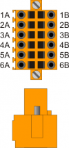 | 1A | Terminal A - RS485 |
| 2A | Terminal B - RS485 | |
| 3A | USER PORT common | |
| 4A | USER PORT common | |
| 5A | Terminal TX - RS232 | |
| 6A | PE - Ground. | |
| 1B | Terminal RX - RS422 | |
| 2B | Terminal RX N - RS422 | |
| 3B | Terminal RX - RS422 | |
| 4B | Terminal TX N - RS422 | |
| 5B | Terminal RX - RS232 | |
| 6B | PE - Ground. |
Setup of USER PORT electric standard
| SW2 | Num. Dip | Name DIP | Setting of DIP | Function | ||
|---|---|---|---|---|---|---|
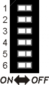 | 1 | JP2 | ON | X1) | X2) | Termination RS485 |
| 2 | JP3 | ON | X3) | X4) | Polarisation RS485 | |
| 3 | JP1 | ON | X5) | X6) | ||
| 4 | OFF | ON | OFF | Selection of USER PORT electric standard | ||
| 5 | ON | OFF | OFF | |||
| 6 | OFF | OFF | ON | |||
| RS485 | RS422 | RS2327) | ||||
CN4 - AUX2 RS485 PORT
 | 1 | 0 Volt - RS485 serial common |
| 2 | Terminal RS485 B | |
| 3 | Terminal RS485 A |
Setup of AUX2 PORT polarisation and termination resistances
| SW4 | Num. Dip | Name Dip | Setting of DIP | Function |
|---|---|---|---|---|
 | 1 | JP3 | ON | Polarisation RS485 |
| 2 | JP2 | ON | Termination RS485 | |
| 3 | JP1 | ON | Polarisation RS485 | |
| 4 | X1) | None |
CN5 - CAN PORT
| | 1 | 0 Volt - CAN common |
| 2 | Terminal CAN L | |
| 3 | Terminal CAN H |
Setup of CAN1 PORT Termination resistances
| SW5 | Num. Dip | Name Dip | Setting of DIP | Function |
|---|---|---|---|---|
| | 1 | JP1 | ON | Termination CAN1 |
| 2 | JP2 | ON | ||
| 3 | - | - | Not used | |
| 4 | - | - |
-
If the termination of CAN1 port is activated, both relative DIP JP1 and JP2 must be activated.
ETHERNET PORT
| ETHERNET PORT | Description |
|---|---|
 | Connector RJ45. LED: * LINK: green led = cable connected (led on indicates that the cable is connected to both ends) * DATA: yellow led = data transmission (flashing led indicates data transmission between the devices connected) |
MMC/SD
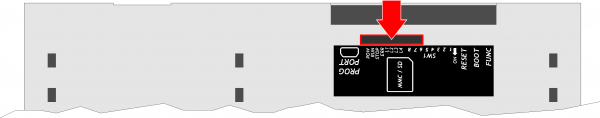 Connector to insert Memory card (marked by an arrow)
CN7 - 1 counter (PP, LD) - MMB axis
| Connector | Pin | ID | Description | Address | ||
|---|---|---|---|---|---|---|
 | 1A | Internal bridge - 1A to 1B | ||||
| 2A | PHA1 | A phase counter 1 | PNP Push-Pull 1) | 3.INP17 | 3.CNT01 | |
| 3A | PHB1 | B phase counter 1 | 3.INP18 | |||
| 4A | Z1 | Z phase counter 1 | 1.INT01 | |||
| 5A | 0V | Common for count inputs | ||||
| 6A | 0V | |||||
| 7A | 0V | |||||
| 1B | Internal bridge - 1A to 1B | |||||
| 2B | PHA1+ | + PHA counter 1 | Line Driver | 3.INP17 | 3.CNT01 | |
| 3B | PHB1+ | + PHB counter 1 | 3.INP18 | |||
| 4B | Z1+ | + Z counter 1 | 1.INT01 | |||
| 5B | PHAN1 | - PHA counter 1 | ||||
| 6B | PHBN1 | - PHB counter 1 | ||||
| 7B | ZN1 | - Z counter 1 | ||||
PNP/Push-Pull type count configuration:
- Terminal 5B: connect to terminal 5A
- Terminal 6B: connect to terminal 6A
- Terminal 7B: connect to terminal 7A
CN8 - 1 counter (PP, LD) - MMC axis
| Connettore | Pin | ID | Description | Address | ||
|---|---|---|---|---|---|---|
| | 1A | Internal bridge - 1A to 1B | ||||
| 2A | PHA2 | A phase counter 2 | PNP Push-Pull 1) | 3.INP19 | 3.CNT02 | |
| 3A | PHB2 | B phase counter 2 | 3.INP20 | |||
| 4A | Z2 | Z phase counter 2 | 1.INT02 | |||
| 5A | 0V | Common for count inputs | ||||
| 6A | 0V | |||||
| 7A | 0V | |||||
| 1B | Internal bridge - 1A to 1B | |||||
| 2B | PHA2+ | + PHA counter 2 | Line Driver | 3.INP19 | 3.CNT02 | |
| 3B | PHB2+ | + PHB counter 2 | 3.INP20 | |||
| 4B | Z2+ | + Z counter 2 | 1.INT02 | |||
| 5B | PHAN2 | - PHA counter 2 | ||||
| 6B | PHBN2 | - PHB counter 2 | ||||
| 7B | ZN2 | - Z counter 2 | ||||
PNP/Push-Pull type count configuration:
- Terminal 5B: connect to terminal 5A
- Terminal 6B: connect to terminal 6A
- Terminal 7B: connect to terminal 7A
CN9 - 1 counter (PP, LD) - MCB axis
| Connettore | Pin | ID | Description | Address | ||
|---|---|---|---|---|---|---|
| | 1A | Internal bridge - 1A to 1B | ||||
| 2A | PHA3 | A phase counter 3 | PNP Push-Pull 1) | 3.INP21 | 3.CNT03 | |
| 3A | PHB3 | B phase counter 3 | 3.INP22 | |||
| 4A | Z3 | Z phase counter 3 | 1.INT03 | |||
| 5A | 0V | Common for count inputs | ||||
| 6A | 0V | |||||
| 7A | 0V | |||||
| 1B | Internal bridge - 1A to 1B | |||||
| 2B | PHA3+ | + PHA counter 3 | Line Driver | 3.INP21 | 3.CNT03 | |
| 3B | PHB3+ | + PHB counter 3 | 3.INP22 | |||
| 4B | Z3+ | + Z counter 3 | 1.INT03 | |||
| 5B | PHAN3 | - PHA counter 3 | ||||
| 6B | PHBN3 | - PHB counter 3 | ||||
| 7B | ZN3 | - Z counter 3 | ||||
PNP/Push-Pull type count configuration:
- Terminal 5B: connect to terminal 5A
- Terminal 6B: connect to terminal 6A
- Terminal 7B: connect to terminal 7A
CN10 - 1 counter (PP, LD) - MT axis
| Connector | Pin | ID | Description | Address | ||
|---|---|---|---|---|---|---|
| | 1A | Internal bridge - 1A to 1B | ||||
| 2A | PHA4 | A phase counter 4 | PNP Push-Pull 1) | 3.INP23 | 3.CNT04 | |
| 3A | PHB4 | B phase counter 4 | 3.INP24 | |||
| 4A | Z4 | Z phase counter 4 | 1.INT04 | |||
| 5A | 0V | Common for count inputs | ||||
| 6A | 0V | |||||
| 7A | 0V | |||||
| 1B | Internal bridge - 1A to 1B | |||||
| 2B | PHA4+ | + PHA counter 4 | Line Driver | 3.INP23 | 3.CNT04 | |
| 3B | PHB4+ | + PHB counter 4 | 3.INP24 | |||
| 4B | Z4+ | + Z counter 4 | 1.INT04 | |||
| 5B | PHAN4 | - PHA counter 4 | ||||
| 6B | PHBN4 | - PHB counter 4 | ||||
| 7B | ZN4 | - Z counter 4 | ||||
PNP/Push-Pull type count configuration:
- Terminal 5B: connect to terminal 5A
- Terminal 6B: connect to terminal 6A
- Terminal 7B: connect to terminal 7A
CN11 - 8 standard digital inputs + 1 rapid input (PNP)
| Connector | Pin | ID | Description | Address |
|---|---|---|---|---|
 | 1 | - | Free | |
| 2 | - | Free | ||
| 3 | 0V | Vout (0 V) - Common for digital inputs I1÷I8 | ||
| 4 | I1 | Fault MMB driver | 3.INP01 | |
| 5 | I2 | Fault MMC driver | 3.INP02 | |
| 6 | I3 | Fault MCB driver | 3.INP03 | |
| 7 | I4 | Start (1)/Stop (0) sinchronism | 3.INP04 | |
| 8 | I5 | Emergency | 3.INP05 | |
| 9 | I6 | Enabling Switch Zero MMB axis | 3.INP06 | |
| 10 | I7 | Enabling Switch Zero MMC axis | 3.INP07 | |
| 11 | I8 | Enabling Switch Zero MCB axis | 3.INP08 | |
| 12 | 0V | Vout (0 V) - Common for digital inputs I1÷I8 |
CN12 - 8 standard digital inputs + 1 rapid input (PNP)
| Connector | Pin | ID | Description | Address |
|---|---|---|---|---|
| | 1 | - | Free | |
| 2 | - | Free | ||
| 3 | 0V | Vout (0 V) - Common for digital inputs I9÷I16 | ||
| 4 | I9 | Manual (0) / Automatic (1) selector | 3.INP09 | |
| 5 | I10 | Start Homing | 3.INP10 | |
| 6 | I11 | Jog forward selected axis | 3.INP11 | |
| 7 | I12 | Jog backward selected axis | 3.INP12 | |
| 8 | I13 | MMB1 axis selection for jog movements | 3.INP13 | |
| 9 | I14 | MMB2 axis selection for jog movements | 3.INP14 | |
| 10 | I15 | MCB axis selection for jog movements | 3.INP15 | |
| 11 | I16 | Free | 3.INP16 | |
| 12 | 0V | Vout (0 V) - Common for digital inputs I9÷I16 |
CN15 - 8 protected digital outputs (24V - 0,5 A)
| Connector | Pin | ID | Description | Address |
|---|---|---|---|---|
 | 1 | V+ | Outputs power in (12-28Vdc) | |
| 2 | O1 | Reset MMB driver | 3.OUT01 | |
| 3 | O2 | Reset MMC driver | 3.OUT02 | |
| 4 | - | n.c. | ||
| 5 | O3 | Reset MCB driver | 3.OUT03 | |
| 6 | O4 | Cycle on signal | 3.OUT04 | |
| 7 | 0V | Outputs power in (12-28Vdc) | ||
| 8 | O5 | Enable MMB driver | 3.OUT05 | |
| 9 | O6 | Enable MMC driver | 3.OUT06 | |
| 10 | O7 | Enable MCB driver | 3.OUT07 | |
| 11 | O8 | Emergency Normally closed | 3.OUT08 |
CN16 - 8 protected digital outputs (24V - 0,5 A)
| Connector | Pin | ID | Description | Address |
|---|---|---|---|---|
| | 1 | V+ | Outputs power in (12-28Vdc) | |
| 2 | O9 | Emergency state lamp | 3.OUT09 | |
| 3 | O10 | Manual state lamp | 3.OUT10 | |
| 4 | - | n.c. | ||
| 5 | O11 | Homing done - machine ready | 3.OUT11 | |
| 6 | O12 | Free | 3.OUT12 | |
| 7 | 0V | Outputs power in (12-28Vdc) | ||
| 8 | O13 | Free | 3.OUT13 | |
| 9 | O14 | Freer | 3.OUT14 | |
| 10 | O15 | Free | 3.OUT15 | |
| 11 | O16 | Free | 3.OUT16 |
CN17 - 4 analog outputs
| Connector | Pin | ID | Description | Address |
|---|---|---|---|---|
 | 1 | GA01 | Common for analog outputs A01÷A02 | |
| 2 | AO1 | MMB axis speed control ±10Vdc | 3.AN01 | |
| 3 | AO2 | MMC axis speed control ±10Vdc | 3.AN02 | |
| 4 | GA02 | Common for analog outputs A03÷A04 | ||
| 5 | AO3 | MCB axis speed control ±10Vdc | 3.AN03 | |
| 6 | AO4 | Free | 3.AN04 |
CN18 - 2 analog inputs, 12bit potentiometric, voltmetric and amperometric
All inputs are Free
A1-HMI-QC050
CN1- Power supply (Slot supply)
| Power supplies available | 24 Vdc | 24 Vac |
|---|---|---|
| Voltage range | 22 ÷ 27 Vdc | +/-15% |
| Max. absorption | 30W | 35VA |
| Frequency | 50/60Hz |
| | 1 | AC power phase/ DC power positive |
| 2 | Gnd-PE (signals) | |
| 3 | AC power phase/ DC power 0V |
CN2 - PORTA USER. Multistandard serial RS232-RS422-RS485 (isolated)
Serial port used to connect hmi with C1-R11-FE30 (RS422).
| | 1A | Terminal A - RS485 |
| 2A | Terminal B - RS485 | |
| 3A | USER PORT common | |
| 4A | USER PORT common | |
| 5A | Terminal TX - RS232 | |
| 6A | PE - Ground. | |
| 1B | Terminal RX - RS422 | |
| 2B | Terminal RX N - RS422 | |
| 3B | Terminal RX - RS422 | |
| 4B | Terminal TX N - RS422 | |
| 5B | Terminal RX - RS232 | |
| 6B | PE - Ground. |