MCE _ P1P20F - 005 : Connections
1. Informations
1.1 Release
This document is valid except for errors or omissions.
| |
|||
| Document: | mce_p1p20f-005 | ||
|---|---|---|---|
| Description: | Manual of electrical connections p1p20f-005 | ||
| Editor: | Michele Sandri | ||
| Approver | Gabriele Bazzi | ||
| Link: | http://www.qem.eu/doku/doku.php/en/strumenti/qmoveplus/j1p20/p1p20f-005/mce_p1p20f-005 | ||
| Language: | English | ||
| Document Release | Description | Note | Date |
| 01 | New manual | 20/04/2017 | |
1.1.1 Specifications/Copyright
The copyright to this manual are reserved. For no reason, this document may be copied or reproduced in any form without the QEM permission.
QEM has no assurances or warranties regarding to content. Qem disclaims any responsibility relating to warranties of fitness for any particular purpose. The informations in this document are subject to change without notice. QEM not assumes responsibility for any error that may appear in this document
Trademarks :
-
QEM® is a registered trademark.
-
Microsoft® and MS-DOS® ar registered trademarks of Windows® and it is a trademark of the Microsoft Corporation.
2. Description
The P1P20F - 005 application, installed in the Qmove J1-P20-FZ20 hardware, manage a standard automatic cutter with 1 move forward axis and 1 optional axis for the cams management. The parameters that determine the mode of operation are only accessible to the installer by the introduction of a password.

3. Hardware and connections
3.1 Base card
3.1.1 Power supply
The instrument must be powered to 24Vdc. No internal fuse will be provided.
3.1.2 Connectivity
Will be provided in “standard Version”, nr. 2 serials:
-
PROG PORT → Serial with TTL logic standard for programming.
-
ETHERNET PORT
Nr. 1 MMC port to save/load data from external memory.
3.1.3 J1-P20-FZ20
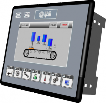 |
| Standard film QEM of the J1-P20FZ20 |
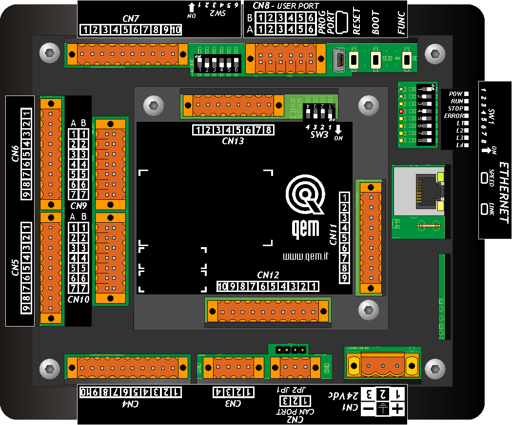 |
| Rear view of the J1-P20FZ20 |
3.1.4 I/O list
In this section we list all the I/O used and divided by connector.
3.1.4.1 Digital inputs (n. 24)
-
NO = Normally open
-
NC = Normally closed
-
I = Impulsive
-
C = Continuous
| NAME | DESCRIPTION | OPERATION | CONNECTOR | CLAMP | HARDWARE | ||
|---|---|---|---|---|---|---|---|
| I1 | Emergency Push Button | NC | C | OFF = Alarm |  | CN6.2 | J1-P20-FZ20 |
| I2 | Manual / Automatic | NO | C | OFF = Manual ON = Automatic | CN6.3 | ||
| I3 | Start / Stop | NO | C | OFF = Stop ON = Start | CN6.4 | ||
| I4 | Stop | NO | I | ON = Stop movement | CN6.5 | ||
| I5 | Free | - | - | - | CN6.6 | ||
| I6 | Restart | NO | I | ON = Restart active | CN6.7 | ||
| I7 | End coil | NO | C | OFF = Film not present | CN6.8 | ||
| I8 | Fault drive WEB | NC | C | ON = Drive OK | CN6.9 | ||
| NAME | DESCRIPTION | OPERATION | CONNECTOR | CLAMP | HARDWARE | ||
|---|---|---|---|---|---|---|---|
| I9 | Fault drive Camme | NC | C | ON = Drive OK | | CN5.2 | J1-P20-FZ20 |
| I10 | Thermal WEB | NC | C | OFF = Alarm | CN5.3 | ||
| I11 | Thermal Cams | NC | C | OFF = Alarm | CN5.4 | ||
| I12 | Motor Cams Brake | NO | C | ON = Alarm | CN5.5 | ||
| I13 | Anti-static bars | NO | C | ON = Alarm | CN5.6 | ||
| I14 | Anti-jam | NO | C | ON = Allarme | CN5.7 | ||
| I15 | Piece counter block | NO | C | ON = blocked | CN5.8 | ||
| I16 | Free | - | - | - | CN5.9 | ||
All the inputs of the CN11 are used as RESERVES.
3.1.4.2 Digital outputs (n. 24)
| NAME | DESCRIPTION | OPERATION | CONNECTOR | CLAMP | HARDWARE | |
|---|---|---|---|---|---|---|
| O1 | Tolerance positioning | C | ON = EV active |  | CN7.2 | J1-P20-FZ20 |
| O2 | End Step | C | ON = EV active | CN7.3 | ||
| O3 | End Program | C | ON = EV active | CN7.4 | ||
| O4 | Stop not occurring | C | ON = EV active | CN7.5 | ||
| O5 | Enabling WEB Drive | C | ON = Drive enable | CN7.6 | ||
| O6 | Cams enabling | C | ON = enable | CN7.7 | ||
| O7 | Air blow 01 | C | ON = EV active | CN7.8 | ||
| O8 | Air blow 02 | C | ON = EV active | CN7.9 | ||
| NAME | DESCRIPTION | OPERATION | CONNECTOR | CLAMP | HARDWARE | |
|---|---|---|---|---|---|---|
| O9 | Quick Accessory | C | ON = EV active | | CN4.2 | J1-P20-FZ20 |
| O10 | Anti-static bars | C | ON = EV active | CN4.3 | ||
| O11 | Anti-jam | C | ON = EV active | CN4.4 | ||
| O12 | Accessory 05 | C | ON = EV active | CN4.5 | ||
| O13 | Accessory 06 | C | ON = EV active | CN4.6 | ||
| O14 | Accessory 07 | C | ON = EV active | CN4.7 | ||
| O15 | Welder 01 | C | ON = EV active | CN4.8 | ||
| O16 | Welder 02 | C | ON = EV active | CN4.9 | ||
| NAME | DESCRIPTION | OPERATION | CONNECTOR | CLAMP | HARDWARE | |
|---|---|---|---|---|---|---|
| O17 | Machine OK | C | ON = no alarms | | CN12.2 | J1-P20-FZ20 |
| O18 | Red lamp | C | ON = EV active | CN12.3 | ||
| O19 | Green lamp | C | ON = EV active | CN12.4 | ||
| O20 | Yellow lamp | C | ON = EV active | CN12.5 | ||
| O21 | Beep | C | ON = EV active | CN12.6 | ||
| O22 | Cams motor brake | C | OFF = brake active | CN12.7 | ||
| O23 | Free | - | - | CN12.8 | ||
| O24 | Free | - | - | CN12.9 | ||
3.1.4.3 Bidirectional counter inputs (n° 2)
| NAME | DESCRIPTION | CLAMP | CONNECTOR | HARDWARE |
|---|---|---|---|---|
| PHA1 PHB1 | Encoder phases cams axis | CN9.2A CN9.3A |  | J1-P20-FZ20 |
| PHZ1 | Cam Axis zeroing Sensor | CN9.4A |
| NAME | DESCRIPTION | CLAMP | CONNECTOR | HARDWARE |
|---|---|---|---|---|
| PHA2 PHB2 | Encoder phases WEB axis | CN10.2A CN10.3A | | J1-P20-FZ20 |
| PHZ2 | Photocell | CN10.4A |
3.1.4.4 Analog outputs (n° 2)
| NAME | DESCRIPTION | CLAMP | CONNECTOR | HARDWARE |
|---|---|---|---|---|
| AO1 | Cams axis drive command 0-10 Vdc | CN3.2 |  | J1-P20-FZ20 |
| AO2 | WEB axis drive command +/- 10Vdc | CN3.3 |
3.1.4.5 Analog inputs (n° 2)
| NAME | DESCRIPTION | CLAMP | CONNECTOR | HARDWARE |
|---|---|---|---|---|
| AI1 | Welder Thermocouple 01 | CN13.3 | 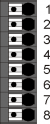 | J1-P20-FZ20 |
| AI2 | Welder Thermocouple 02 | CN13.6 |
3.2 Diagnostic
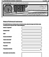
To access the diagnostics section:
-
press MENU button on the top bar

-
Access the diagnostic with the
 button

From this screen you can access the various diagnostic sections:
-
Digital Input Diagnostics
-
Digital Output Diagnostics
-
Counts Diagnostics
-
Analog Output Diagnostics
-
Analog Input Diagnostics
3.2.1 Digital Input Diagnostics
Press the digital inputs button to access the following screen, where is showed the status of each input.

To scroll through the various pages, if present, use the ![]() and
and ![]() buttons on the top bar.
buttons on the top bar.
To return to the diagnostic menu press the ![]() button
button
3.2.2 Digital Output Diagnostics
Pressing the button for the digital outputs will take you to the following screen, where is showed the status of each output.

To scroll through the various pages, if presents, use the ![]() and
and ![]() buttons on the top bar.
buttons on the top bar.
3.2.2.1 Forcing the outputs
To access the output forcing function:
-
Press top where the page title DIGITAL OUTPUTS is showed
-
The title changes to ACTIVE FORCING and starts blinking → Active function
-
Press the output to activate it. Press again to turn it off.
-
Press the title space to turn off the function.
-
When the page exits, the function automatically switches off.
To return to the Diagnostics menu press the ![]() button
button
3.2.3 Counts Diagnostics
The following screen is accessed by pressing the Counts button.

To return to the Diagnostics menu press the ![]() button
button
3.2.4 Analog Output Diagnostics
By pressing the button for the analog outputs, the following screen is showed.

The analog output is expressed in volts.
To return to the Diagnostics menu press the ![]() button
button
3.2.5 Digital Input Diagnostics
Press the digital inputs key to access the following screen.

To return to the Diagnostics menu press the ![]() button
button
4. Assistance
For supplying you fast service, at the lowest cost, we need your support.
 |  |
| Follow all instructions provided in the MIMAT manual | If the problem remains, fill out the “Request Form for assistance” on the page Contacts at www.qem.it site. Our technicians will get elements essential for the understanding of your problem. |
Repair
To provide you with an efficient service, please read and adhere to the instructions given here
Shipping
It is recommended to pack the instrument with materials that are able to cushion any falls.
 |  |  |
| Use the original package: it must protect the instrument during transport. | Attach: 1. A description of the anomaly; 2. A part of the electric scheme where the equipment is inserted 3. The planning of the equipment (set up, quotas of job, parameters…). 4. Request a quote for repair; if not required, the cost will be calculated in the final balance. | A full description of the problem, will help identify and resolve your problems fast. A careful packaging will avoid further inconveniences. |