This is an old revision of the document!
MDO_P1P44F-010: Operator Manual
 |  |
1. Informations
1.1 Release
| |
|||
| Document: | mdo_p1p44f-010 | ||
|---|---|---|---|
| Description: | p1p44f-010 Operator Guide | ||
| Editor: | Michele Sandri | ||
| Approver | Gabriele Bazzi | ||
| Link: | http://www.qem.eu/doku/doku.php/en/strumenti/qmoveplus/j1p44/p1p44f-010/mdo_p1p44f-010 | ||
| Language: | English | ||
| Document Release | Description | Note | Data |
| 01 | New Manual | 27/08/2019 | |
1.1.1 Specifications/Copyright
The copyright of this manual is reserved. No part of this document can be copied or reproduced in any form without the prior written permission of the QEM.
QEM has no assurances or guarantees on the content and specifically disclaims any liability inherent in the guarantees of eligibility for any particular purpose. The information in this document is subject to change without notice. QEM does not take any responsibility for any errors that may appear in this document.
Trademarks:
-
QEM® is a registered trademark.
2. General features
2.1 Description
The J1-P44-FB20 innstrument with the P1P44F-010 software, it's suitable for automating a machine type: “cutter for stone processing”.
2.2 Workings
-
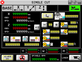
single cut
-
tile cutting
-
tilt cut 1)
-
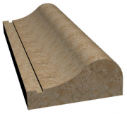
profiling
-
drawing profiles with Mini Cad inside
-
profile drawings with Cad on PC and importing on the instrument with “ Profile Importer 8” program with USB or LAN key
-
table flattening
2.3 Options
-
the W table can be motorized or manual
-
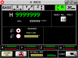
the H-axis may or may not be there, if present it can be manual or motorized or only mechanical (without encoder)
2.4 Features
-
The axes can be controlled with:
-
normal positioning
-
with the conclusion of the positioning with “pulse technique”, which allows you to achieve greater accuracy, if mechanical inertia tended to make the positioning wrong.
If due to the mechanics and type of inverter, the final part of the positioning was incorrect, the tool to overcome this problem, provides this functionality.
Typically, it is used on the Table or W-axis, on which very different weights can be loaded between them…causing a NOT constant space of inertia .
-
Bridge lifting alarm: If the Z-axis were to happen, pressing down would lift the bridge, the limit switch installed on the bridge and connected to the I67 input will activate the alarm.
-
Manage of X Y Z + W (Table rotation) axes + H (disk tilt).
The H encoder is connected to the J1-P44-FB20 instrument, while the X Y Z-W encoders are connected to the RMC1S modules
-
Errors in the mechanics of the W and H axes can be corrected by providing no.8 linearization sectors.
-
There is a table in which you can set the maximum diameter and turns of the cutting disk.
-
Measuring and displaying the current of the cutting disc; the maximum current setting is allowed.
2.5 Executable working

Multiple Cut
Tile Cut
Tilted cut
Profiling
Flattening3. Hardware
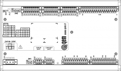
J1-P44-FB20 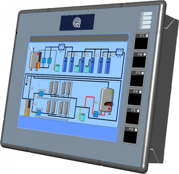
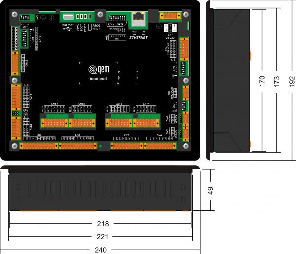

J1-P44-Fx:Installation and Maintenance Manual RMC-1SC01E1/DP1/24Vdc 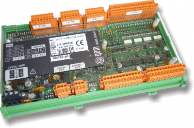
RMC-1SC01:Installation and Maintenance Manual 3.1 Function and LED keys
Key Icon Function Led Key Icon Function Led F1 
Start Cycle - F4 
Semi-automatic = ON Active semi-automatic F2 
Stop Cycle - F5 
Alarm = ON Alarm F3 
Restart - F6 
Exit - - - - - - - - - - - - - - - - - - - - - - - - - - - - - - - - -
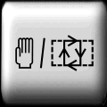
3.2 Symbols and keys
Key Description ———————– Top bar symbols Description 
Press to confirm 
In initialization 
Selection 
Emergency 
Previous page 
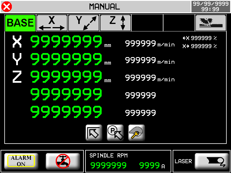
Manual 
Next page 
Homing active 
Reserved area 
Semi-automatic 
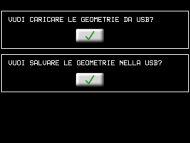
Open file from USB 
Automatic - cycle OFF 
Save 
Automatic - cycle ON 
Working preview 
Calibration mode 
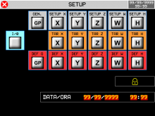
Protected/Unprotected Setup The yellow data is editable 3.3 Startup
START
The instrument waiting the input to be activated
“activated auxiliaries”1) to automatically go
to the next page
Important: pressing the button
you can navigate the HMI, with the machine stationary
HOMING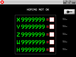
OR
F6
for exit
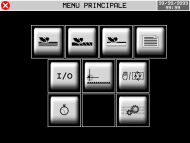
MAIN MENU
1) These are the 24 Volt dc power supplies of the RMC1S modules, limit switches, encoders, relays, etc.4. Main menu
F6 


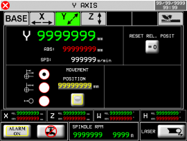
5. Homing
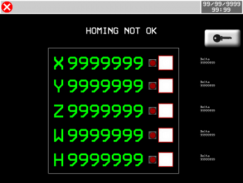

Axis enabled for homing procedure 
Homing OK 
Axis not enabled for homing procedure 
Homing not OK 
Delta error compared to previous homing 
ALWAYS homing before moving to the MANUAL page.
If homing is missing, it affects the functionality of the machine.5.1 Homing procedure
-
Activate the MANUAL
-
Check that there are no ALARMS
-
Select the axes to homing
-
Press START (I10) or F1
-
If the Homings procedure was successful, the green led is turned on
-
If an error occurred during the Homing process, the red is turned on
-
Verify that the error delta (number that appears next to each axis) is = 0 (about)
5.2 Error Delta
This data indicates the Error Delta compared to previous homing, with this value you can easily check if an encoder is good or is broken.
Procedure:
-
Execute an homing 1)
-
Move the axis in manual, numerous times forward and backward
-
Then, without turning off the machine, re-execute the homing
-
The second homing will make it take on an “important” meaning to this number: will show us how much is the offset of the count compared to the actual physical position of the machine
-
If the encoder counts well, this offset must be = 0
-
Then, in practice, this number probably won't always be just = 0 due to the tolerance of limit switch used to do homing
-
Repeating the homing several times, you will be able to realize if the number shows a faulty encoder, or an error given by the tolerance of the limit switch
-
A small error not always repetitive, evidence the tolerance of the limit switch
-
A big error, it will show clearly, a problem to the encoder
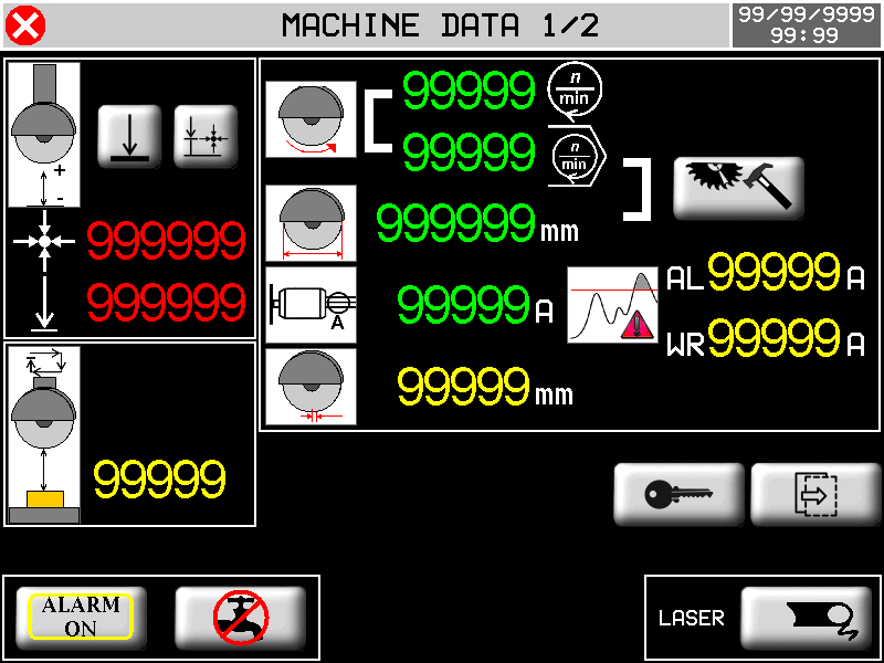
1) The first time you execute an homing (after the instrument is turned on), this number doesn't have a utility6. Machine datas
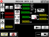
MAIN MENU


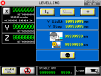
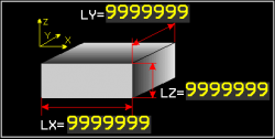
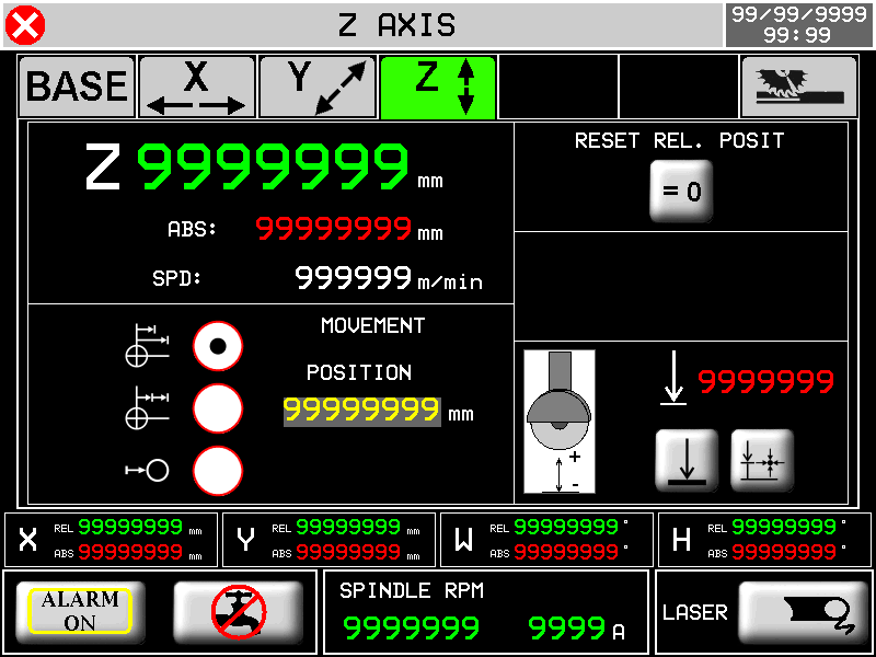
Setting Minimum location Z

Automatic setting Minimum location Z

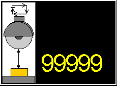
SECURITY QUOTE setting

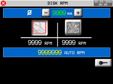
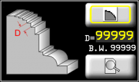
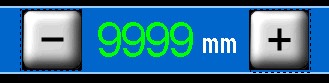
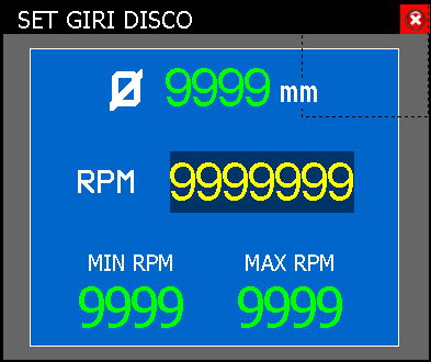
 Disk RPM
  Disk diameter Diameter and RPM setting
  Current Disk Absorption
AL : Maximum current setting
WR : Early warning threshold setting Disk thickness setting
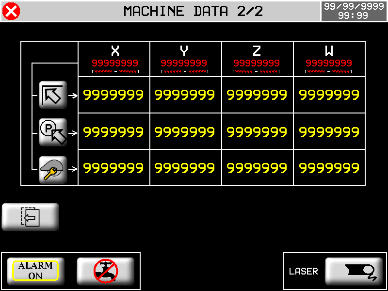
  Out-of-clutter position
  Parking position
  Tool change position
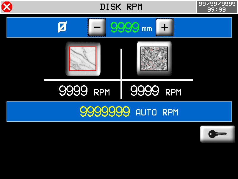
 DISK DIAMETER AND RPM  Disk diameter
  Marble
  Granite
  Automatic RPMs based on disk diameter - Setting an RPM Override
 7. Bottom bar

 : Active Stateflow Alarm
 : Off Stateflow Alarm
  : EV water deactivates
 : EV active water SPINDLE RPM
Ø : Current diameter
RPM : Set the desired rounds
MIN RPM : Minimum setable value
MAX RPM : Maximum setable value99999 A Instantaneous absorption of spindle current. If the WRN symbol appears above the current absorption indication, it means that the pre-alarm threshold has been exceeded.  : EV laser disables
 : EV laser active
 8. Manual/Semi-Automatic
F6


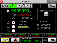


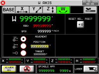

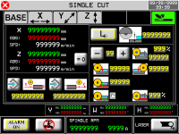


Out-of-clutter position Parking position Tool change position


TARGET POSITION SET -  ABSOLUTE TARGET POSITION
- INCREMENTAL TARGET POSITION
- 0 TARGET POSITION
 Reset Relative Position


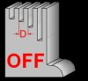
Disk Compensation
 OFF
OFF
 ON
ON 

Minimum Z Position
Z Minimum Position Self-Learning


X positions self-learning 
X START Cut Position 
X END Cut position 
Single Pass 
Greek cutting 
Cut Depth Set dati del taglio a greca (max 10)
 01
01 

% Reducing the speed of the first cut 
Forward lowered (X+) 
Backward lowered (X-) Last Cut Direction


Last lowered depth 
% Reducing the speed of the last cut 8.1 Semi-Automatic Execution
-
Check that you are in manual
-
F4 →
-
external START key (I10) or F1
-
the axis reaches the set dimension or single-cut is executed.
9. Reset axes
The reset axes function reset RELATIVE quotas
-
Check you're in manual mode
F3

-
X - : hold to reset the X-axis count
-
Y - : hold to reset the Y-axis count
-
Z - : hold to reset the Z-axis count
-
F6 - Exit from the page
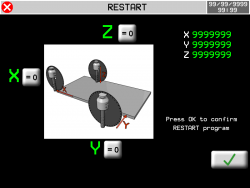
10. Restart working
The restart function restarts the loaded working from the beginning
-
Check that you're in manual mode
-
Check that you're on one of the work pages
F3
in case of cutting slabs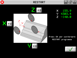
in case of profiling-
OK -
 : press to confirm the restart and exit the page
 -
F6 - Exit from the page without confirmation
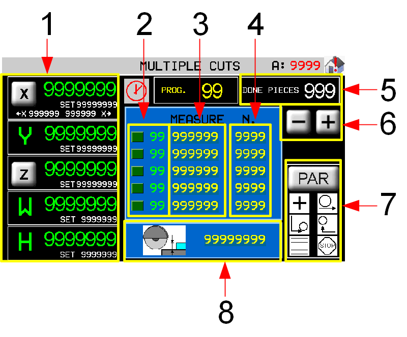
11. Muliple Cuts/Automatic
F6
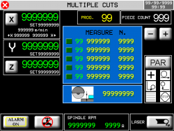


11.0.1 Without table rotation

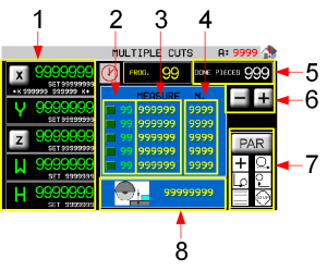
1 Current positions and axis target dimensions
2 Current work step
3 Size of the cut (Y)
4 Number of cuts to be execute
5 Pieces counter
6 Cuts list scroll (1-10)
7 Working parameters
8 Cutting Depth (Z)11.0.2 With table rotation

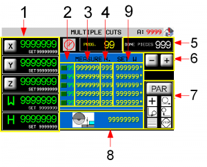
1 Current positions and axis target dimensions
2 Current work step
3 Size of the cut (Y)
4 Number of cuts to be execute
5 Pieces counter
6 Cuts list scroll (1-10)
7 Working parameters
8 Cutting Depth (Z)
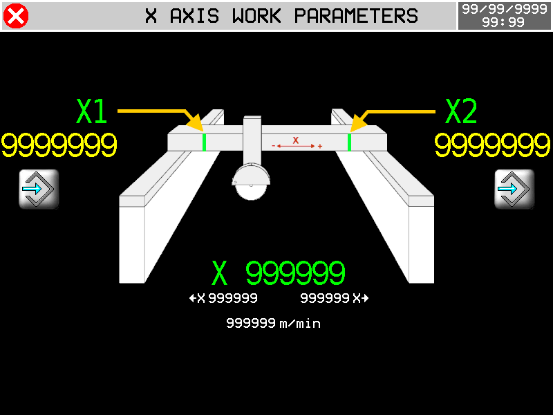
9 Table rotation (W)11.0.3 Axes parameters

WITHOUT TABLE ROTATION

WITH TABLE ROTATION
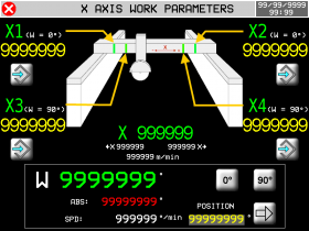
 Self-learning positions X1 + X2 = Table (W) to 0°…..X3 + X4 = Table (W) to 90°
N.B. the disc must exit the slab before learning the X1 - X2 dimensions or X3 - X4 dimensions.
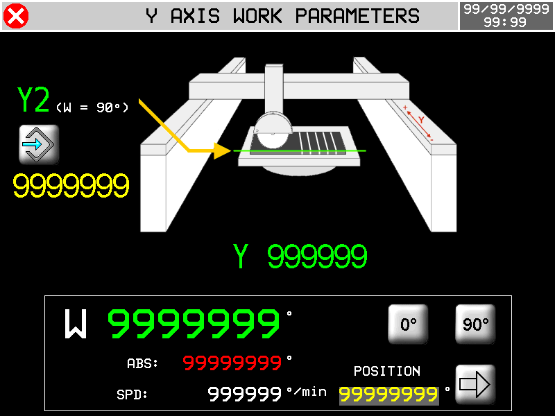
 Self-learning position Y2 = Start position with Table (W) to 90°
 Start of cut X End of cut X W Quick Move the Table 


Immediate position : 0°
Immediate position : 90°
Immediate position set

Input data set
0 ~ 10 Last Cut Direction
Forward lowered (X+) Backward lowered (X-) Last Cut Depth % Reducing last cut speed First cut
% Reducing first cut speed
Position of first increment of passes cut.Advance
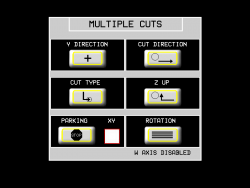
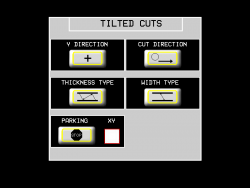
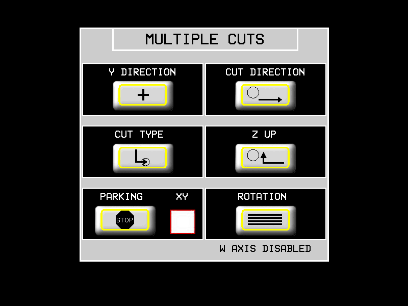
Space before FC software X when Z begins the lowered11.0.4 Working parameters


Y DIRECTION POSITIVE The piece thickness is made with Y that increment

NEGATIVE The piece thickness is made with Y that decrements

CUT DIRECTION X+ Forward only

BILATERAL to greek

CUT TYPE SINGLE one pass

TO LOWERED multi-pass

Z LIFT Z lift when X is in the FORWARD POSITION

X and Z come out TOGETHER from the slab

END CYCLE The axes STOPPED when the cycle is end

The disk goes to PARKING at the end of the cycle

XY
X and Y axes in parking one after another
Assi X e Y in parcheggio contemporaneamente.ROTAZIONE WITHOUT TABLE ROTATION

WITH TABLE ROTATION

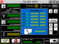
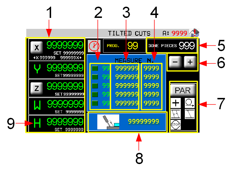
12. Tilted Cuts/Automatic
F6 
H axis without ENCODER

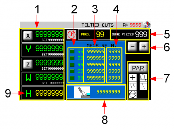
1 Current positions and axis target dimensions
2 Current work step
3 Size of the cut (Y)
4 Number of cuts to be execute
5 Pieces counter
6 Cuts list scroll (1-10)
7 Working parameters
8 Cutting Depth (Z)
9 Settable cut angle (I) Axes parameters - see Multiple Cuts H axis with ENCODER

1 Current positions and axis target dimensions
2 Current work step
3 Size of the cut (Y)
4 Number of cuts to be execute
5 Pieces counter
6 Cuts list scroll (1-10)
7 Working parameters
8 Cutting Depth (Z)
9 Settable cut angle (I) Axes parameters - see Multiple Cuts 12.0.1 Parametri di lavorazione
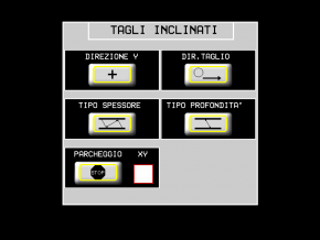
DIREZIONE Y POSITIVA Lo spessore pezzo è fatto con Y che si incrementa
NEGATIVA Lo spessore pezzo è fatto con Y che si decrementa
DIREZIONE TAGLIO X+ Solo avanti
BILATERALE a greca
TIPO DI AMPIEZZA Spessore a 90° rispetto al taglio

Spessore PARALLELO alla superficie della lastra

TIPO PROFONDITA' Profondità = lungo il disco

Profondità = 90° rispetto alla superficie della lastra

FINE CICLO Gli assi SI FERMANO una vola finito il ciclo
Il disco va in PARCHEGGIO alla fine del ciclo
XY
Assi X e Y in parcheggio uno dopo l'altro
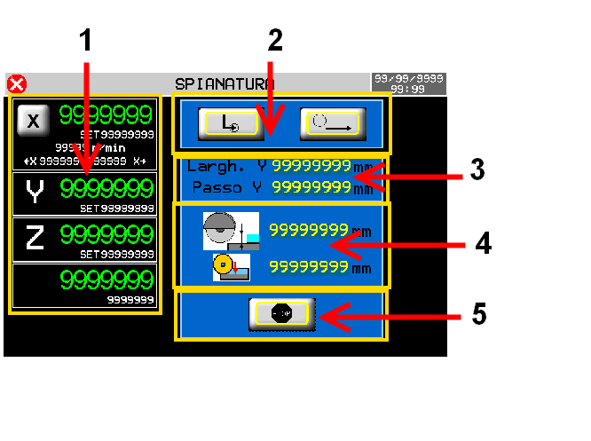
Assi X e Y in parcheggio contemporaneamente.13. Spianatura
 F6
F6


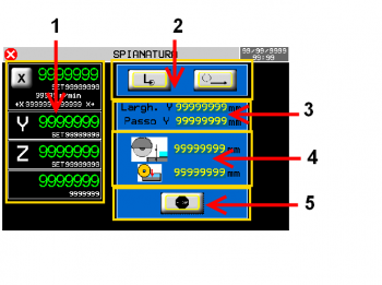
1 Posizioni attuali e quote target assi
2 Parametri della lavorazione
3 Ampiezza della superfice e del passo
4 Profondità del taglio e incremento
5 Parcheggio a fine lavorazione13.0.1 Dati della lavorazione
Largh. Y Larghezza totale della parte che deve essere spianata. Passo Y Valore del passo che compie l'asse Y dopo ogni taglio. Profondità Z

Profondità del taglio.
Usato se è impostato il taglio a calate.Passo Z

Valore del passo che compie l'asse Z ad ogni passata.
Usato se è impostato il taglio a calate.
13.0.2 Parametri degli assi
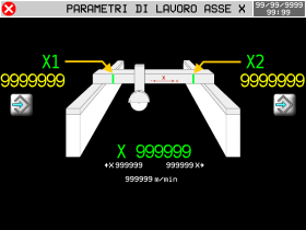
Autoapprendimento delle posizioni X1 + X2 = Finecorsa software di taglio
N.B. il disco deve uscire dalla lastra prima di apprendere le quote X1 - X2
13.0.3 Parametri di lavorazione
TIPO DI TAGLIO SINGOLO una passata
A CALATE multipassata
DIREZIONE TAGLIO X+ Solo avanti
BILATERALE a greca
DIREZIONE Y POSITIVA Lo spostamento di Y avviene nel verso positivo
NEGATIVA Lo spostamento di Y avviene nel verso negativo
FINE CICLO Gli assi SI FERMANO una vola finito il ciclo
Il disco va in PARCHEGGIO alla fine del ciclo
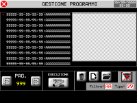
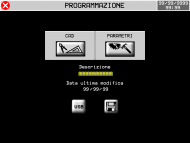
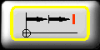
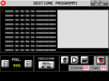
14. Programmazione ed esecuzione dei profili
F6


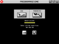

ESECUZIONE

14.1 Filtro della lista programmi
 Usando il filtro della lista programmi è possibile visualizzare velocemente il programma desiderato, senza scorrere l'intera lista. Il sistema prevede due tipi di filtraggio che possono essere combinati insieme:
-
Filtro sulla descrizione programmi
-
Filtro del tipo programma
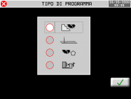
Cosa significa “Tipo programma” :
Tipo Descrizione 0 Mostra tutti i programmi 1 Mostra solo programmi di profilatura 2 Mostra solo programmi di fresatura Non abilitati in questa versione 3 Mostra solo programmi di taglio poligoni Non abilitati in questa versione 14.2 Profili

 F6
F6


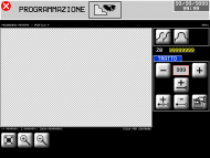


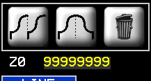
14.2.1 Profili - CAD

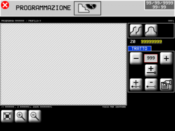


Ripeti sagoma 
Specchia sagoma Z0 = origine
Coordinata Y = 0
Zoom in 
Zoom out 
Adatta allo schermo 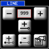
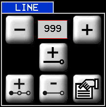
 000
000 
Scorrere per scegliere il tratto desiderato 
Aggiungi un tratto 
Inserisci un tratto 
Cancella un tratto 
Proprietà del tratto

Tipi di tratto 


Assoluto
le coordinate finali sono assolute rispetto all'origine
Incrementale
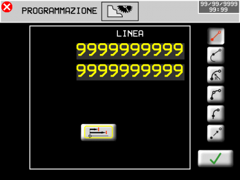
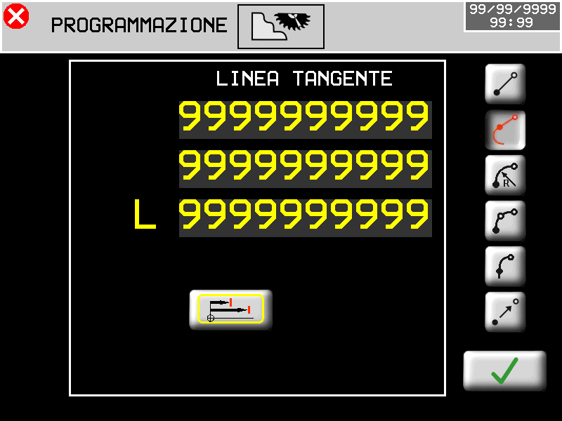
le coordinate finali sono relative rispetto alla fine del tratto precedente- - - - - - - - - - - - - - - - - - LINEA


Inserire le coordinate finali LINEA TANGENTE


Inserire la coordinata Y 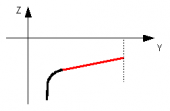
Inserire la coordinata Z 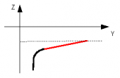
Inserire L = lunghezza 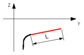
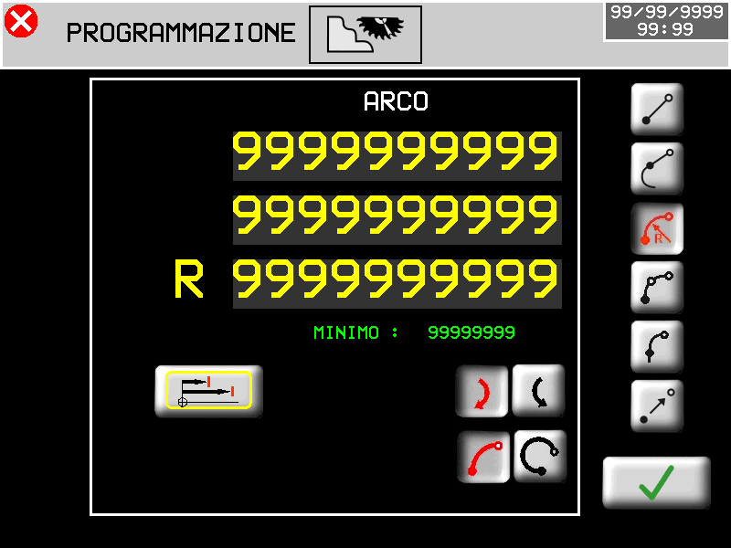
ARCO CON RAGGIO


Inserire le coordinate finali e il raggio
MINIMO è il minimo raggio possibile orario
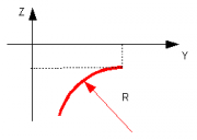
 antiorario
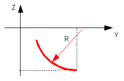
Scelta della direzione della curva
 orario OPPURE
  antiorario
 arco breve OPPURE
  arco lungo
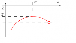
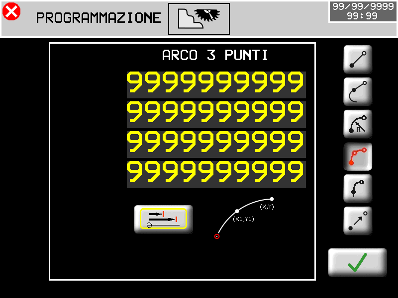
Il programma mostra il minor valore di raggio possibileARCO PER 3 PUNTI


Inserire le coordinate del punto finale e del punto intermedio
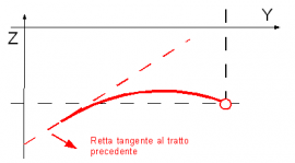
ARCO TANGENTE

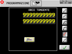
Inserire le coordinate del punto finale
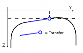
TRASFERIMENTO


Tratto di spostamento senza tagli. Inserire le coordinate del punto finale
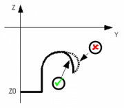
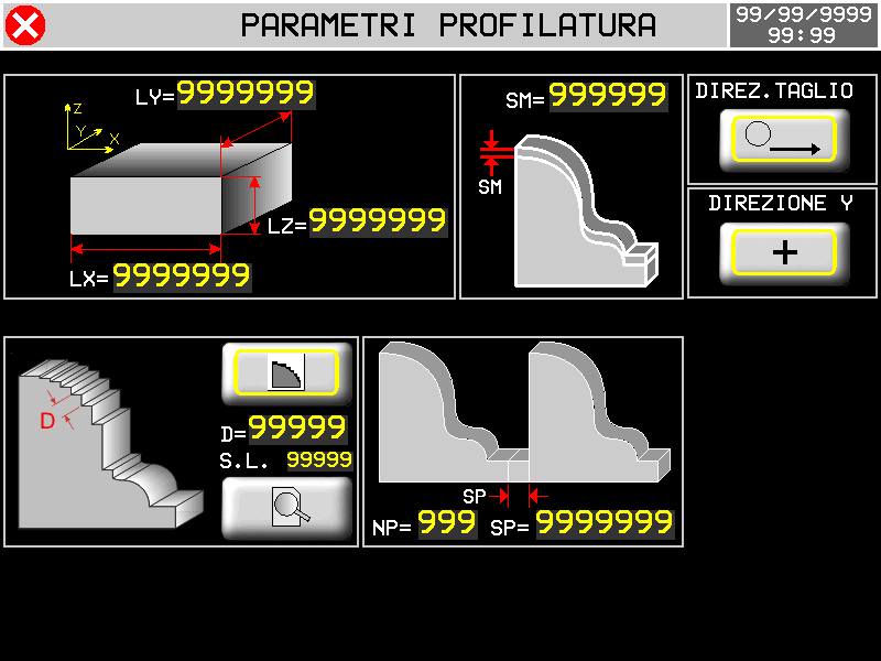
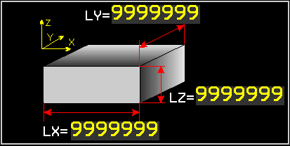
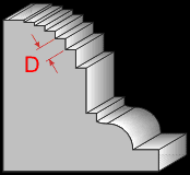
Il software corregge automaticamente i sottosquadra. 14.2.2 Profili - parametri


Dimensioni del massello. Come opzioni è possibile inserire
le dimensioni del massello. Questo sarà disegnato in grigio nelle
pagine di CAD e di anteprima lavorazione.
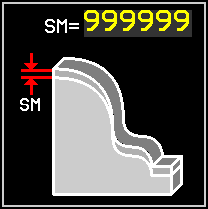
Sovra Materiale sul profilo

Direzione di taglio solo verso X+
Taglio bilaterale
Direzione incremento asse Y
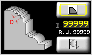
Distribuzione dei tagli
Tipo strategia

Spessore del disco

Anteprima dei tagli


Distribuzione lungo il profilo


Distribuzione lungo l'asse Y
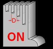
ON: taglio garantito sui punti notevoli


Distribuzione lungo l'asse Y
OFF: i punti notevoli non vengono processati
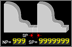
Ripetizione lavorazione
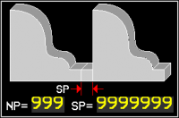
NP = Numero di ripetizioni
SP = Spazio tra le ripetizioni15. Esecuzione
15.1 Esecuzione di un programma
F6
Scegliere e selezionare il programma per visualizzare l'anteprima
ESECUZIONE


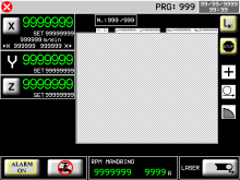
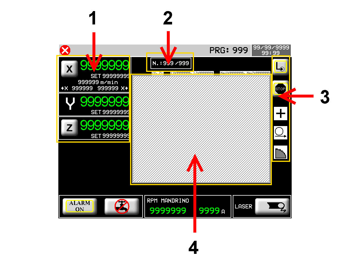
15.1.1 Esecuzione di un profilo
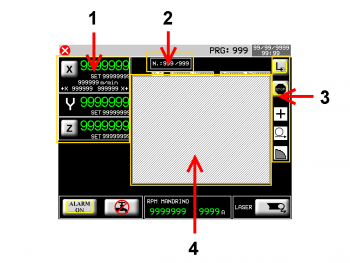
1 Posizioni attuali e quote target assi
2 Sagoma in esecuzione
3 Parametri della lavorazione
4 Anteprima della sagoma disegnata15.1.2 Parametri degli assi

Autoapprendimento delle posizioni X1 + X2 = Finecorsa software di taglio 
Set dei dati di calata
0 ~ 10 Direzione ultimo taglio
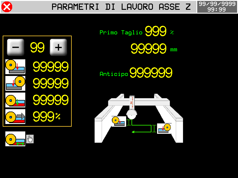
Calata avanti (X+) calata indietro (X-) Profondità ultimo taglio % Riduzione velocità ultimo taglio Primo Taglio
% Riduzione velocità del primo taglioAnticipo
Spazio prima del FC software X quando Z comincia la calata15.1.3 Parametri di lavorazione
TIPO DI TAGLIO SINGOLO una passata

A CALATE multipassata

FINE CICLO Gli assi SI FERMANO una vola finito il ciclo

Il disco va in PARCHEGGIO alla fine del ciclo

I seguenti simboli sono in sola visualizzazione
Sono programmati nelle apposite pagine di parametri.DIREZIONE Y POSITIVA Il taglio successivo è fatto con Y che si incrementa

NEGATIVA Il taglio successivo è fatto con Y che si decrementa

DIREZIONE TAGLIO X+ Solo avanti

BILATERALE a greca

STRATEGIA TAGLI LUNGO IL PROFILO

TAGLI LUNGO Y - Notevoli ON

TAGLI LUNGO Y - Notevoli OFF

Alla pressione del bottone di START CICLO,la macchina parte con la lavorazione impostata.16. Allarmi
F5

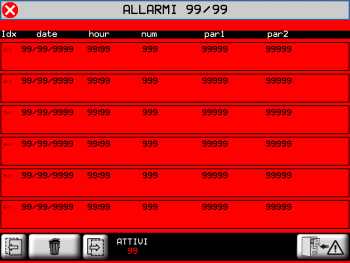

Cancella tutti gli allarmiGli allarmi bloccano tutte le operazioni della macchina.
Allarme Causa Soluzione Emergenza Stop per fungo di emergenza - Finecorsa asse Y avanti L'asse Y ha impegnato il finecorsa avanti - Finecorsa asse Y indietro L'asse Y ha impegnato il finecorsa indietro - Finecorsa asse Z alto L'asse Z ha impegnato il finecorsa alto - Finecorsa asse Z basso L'asse Z ha impegnato il finecorsa basso - Finecorsa asse X avanti L'asse X ha impegnato il finecorsa avanti - Finecorsa asse X indietro L'asse X ha impegnato il finecorsa indietro - Finecorsa asse H avanti L'asse H ha impegnato il finecorsa avanti - Finecorsa asse H indietro L'asse H ha impegnato il finecorsa indietro - Lama non in rotazione Il disco deve essere in movimento durante il ciclo automatico - Mancanza pressione acqua Mancanza acqua di raffreddamento Controllare il flussostato Overcurrent motore lama L'assorbimento del motore del disco è oltre la soglia di allarme - Mancanza pressione olio Mancanza pressione nel circuito di lubrificazione Controllare il pressostato dell'olio Anomalia encoder X Mancata rilevazione conteggio Controllare la bontà dell'encoder Anomalia encoder Y Anomalia encoder Z Anomalia encoder W Anomalia encoder H Scatto di un termico Un termico dei drive è scattato - Fault inverters Fault di uno degli inverter degli assi - Fault driver mandrino Fault dell'inverter del mandrino - Primo modulo RMC1S disconnesso Il modulo remoto non comunica Controllare i settaggi e il cavo di comunicazione Modulo RMC2S disconnesso Asse X fuori tolleranza Posizionamento concluso fuori tolleranza Controllare i parametri dell'asse Asse Y fuori tolleranza Asse Z fuori tolleranza Asse W fuori tolleranza Asse H fuori tolleranza Barriere interrotte Le barriere di protezione perimetrale sono state aperte - Mancanza pressione aria Mancanza pressione nel circuito dell'aria Controllare il pressostato dell'aria Attesa attivazione ausiliari… Ingressi ausiliari non attivi. Comunicazione interrotta con il 2° modulo RMC1S all'ingresso I62. Attivare gli ingressi ausiliari. Controllare la comunicazione con il 2° modulo RMC1S. Mancanza ausiliari Gli ausiliari della macchina sono caduti - Anomalia degli inverter Gli inverter presentano un errore non resettabile Contattare il produttore dell'inverter Ponte sollevato Segnala che il ponte si è sollevato ed è intervento il fine corsa dell'ingresso I67. Resettare l'allarme e riportare in manuale il ponte sui binari
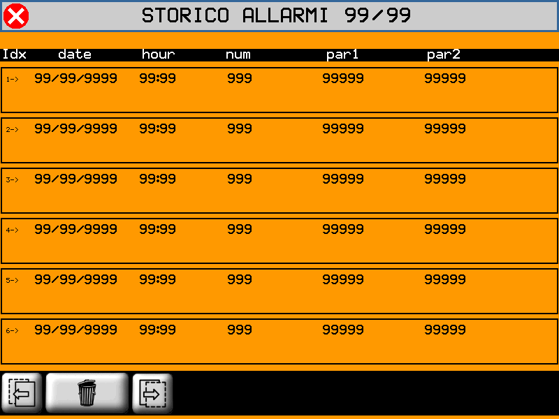
16.1 Storico allarmi

 per cancellare lo storico allarmi
16.2 Messaggi
I messaggi non bloccano le operazioni della macchina.
Messaggio Causa Soluzione ATTENDERE… Si stanno processando dei dati - ERRORE PERCORSO Errore nel calcolo del percorso assi. L'utensile è troppo largo LAMA INCLINATA L'inclinazione disco non è compatibile con la lavorazione in corso Correggere l'inclinazione X OVER MAX LIMIT La quota target dell'asse è oltre il finecorsa massimo - Y OVER MAX LIMIT - Z OVER MAX LIMIT - X OVER MIN LIMIT La quota target dell'asse è oltre il finecorsa minimo - Y OVER MIN LIMIT - Z OVER MIN LIMIT - LAVORO CONCLUSO Il ciclo automatico è terminato con successo - X FUORI POSIZIONE La posizione di X non è corretta La posizione di X è dentro i finecors software di taglio ESEGUIRE HOMING L'Homing non è stato eseguito Eseguire la procedura GEOMETRIA VUOTA Si tenta di aprire una geometria inesistente - ATTESA START… La lavorazione attende il comando di START - ERRORE COMPENSAZIONE Errore nel calcolo della compensazione disco Controllare il disegno della sagoma ACCENDERE L'UTENSILE Avviare il disco per iniziare il ciclo - Y OLTRE QUOTA MAX/MIN I dati di lavorazione richiedono un movimento di Y oltre i limiti software - PONTE SOLLEVATO Il ponte è sollevato Vedi descrizione segnalazione Allarmi 17. Diagnostica
F6


PASSWORD:462
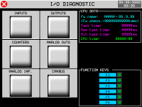
I/O

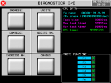
INGRESSI

USCITE
CONTEGGI
USCITE ANALOGICHE
INGRESSI ANALOGICI
COMUNICAZIONE CON I MODULI RMC1S
17.1 CPU DATA
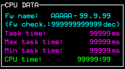
Fw name : codice firmware e relativo checksum
Task time : tempo medio del ciclo CPU
Maximum Time e Minimum Time limiti registrati
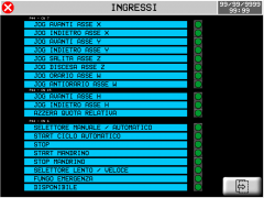
CPU time : tempo totale della CPU nello stato di RUN (hh:mm)17.2 Ingressi digitali
INGRESSI


Stato degli ingressi digitali
 = OFF
= OFF
= ONPagina precedente Pagina successiva
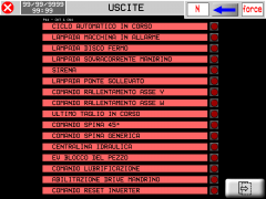
17.3 Uscite digitali
USCITE
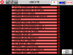
Stato delle uscite digitali
= OFF
 = ON
= ON Pagina precedente Pagina successiva 
Premere per passare alla modalità di forzatura uscite
Premere sull'uscita che si intende attivare.
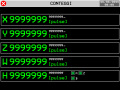
17.4 Conteggi encoder
CONTEGGI

Posizione assi

Stato dei canali encoder
= OFF
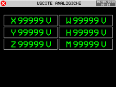
= ON 17.5 Uscite analogiche
USCITE AN.
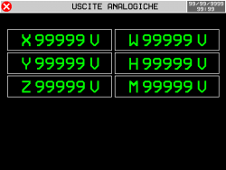
Voltaggio uscite analogiche
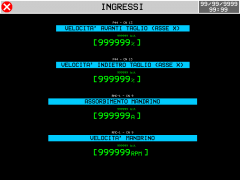
17.6 Ingressi analogici
INGRESSI AN.
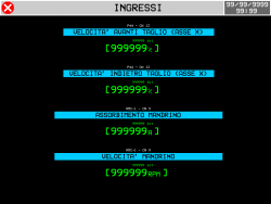
Lettura ingressi analogici
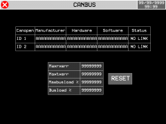
17.7 Comunicazione con i moduli RMC1S
CANBUS

Stato della comunicazione con i moduli RMC1S. 18. Assistenza
Per poterti fornire un servizio rapido, al minimo costo, abbiamo bisogno del tuo aiuto.

Segui tutte le istruzioni fornite nel manuale MIMAT Se il problema persiste, compila il “Modulo richiesta assistenza” nella pagina Contatti del sito www.qem.it.
I nostri tecnici otterranno gli elementi essenziali per comprendere il tuo problema.Riparazione
Per poterVi fornire un servizio efficente, Vi preghiamo di leggere e attenerVi alle indicazioni qui riportate
Spedizione
Si consiglia di imballare lo strumento con materiali in grado di assorbire eventuali cadute.


Utilizzare l'imballo originale: deve proteggere lo strumento durante il trasporto. Allega:
1. Una descrizione dell'anomalia;
2. Parte dello schema elettrico in cui è inserito lo strumento
3. Programmazione dello strumento (setup, quote di lavoro, parametri…).Una descrizione approfondita del problema ci consentirà di identificare e risolvere rapidamente il tuo problema.
Un accurato imballaggio eviterà ulteriori inconvenienti. -


- Last modified: 2020/04/03 14:31