MDO_P1P44F-010: Operator Manual
 |  |
1. Informations
1.1 Release
| |
|||
| Document: | mdo_p1p44f-010 | ||
|---|---|---|---|
| Description: | p1p44f-010 Operator Guide | ||
| Editor: | Michele Sandri | ||
| Approver | Gabriele Bazzi | ||
| Link: | http://www.qem.eu/doku/doku.php/en/strumenti/qmoveplus/j1p44/p1p44f-010/mdo_p1p44f-010 | ||
| Language: | English | ||
| Document Release | Description | Note | Data |
| 01 | New Manual | 27/08/2019 | |
| 02 | Add Description and Y-Axis Calculation Function Page | 31/03/2021 | |
1.1.1 Specifications/Copyright
The copyright of this manual is reserved. No part of this document can be copied or reproduced in any form without the prior written permission of the QEM.
QEM has no assurances or guarantees on the content and specifically disclaims any liability inherent in the guarantees of eligibility for any particular purpose. The information in this document is subject to change without notice. QEM does not take any responsibility for any errors that may appear in this document.
Trademarks:
-
QEM® is a registered trademark.
2. General features
2.1 Description
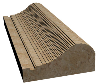
The J1-P44-FB20 innstrument with the P1P44F-010 software, it's suitable for automating a machine type: “cutter for stone processing”.
2.2 Workings
-
single cut
-
tile cutting
-
tilt cut 1)
-
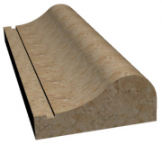
profiling
-
drawing profiles with Mini Cad inside
-
profile drawings with Cad on PC and importing on the instrument with “ Profile Importer 8” program with USB or LAN key
-
table flattening
2.3 Options
-
the W table can be motorized or manual
-
the H-axis may or may not be there, if present it can be manual or motorized or only mechanical (without encoder)
2.4 Features
-
The axes can be controlled with:
-
normal positioning
-
with the conclusion of the positioning with “pulse technique”, which allows you to achieve greater accuracy, if mechanical inertia tended to make the positioning wrong.
If due to the mechanics and type of inverter, the final part of the positioning was incorrect, the tool to overcome this problem, provides this functionality.
Typically, it is used on the Table or W-axis, on which very different weights can be loaded between them…causing a NOT constant space of inertia .
-
Bridge lifting alarm: If the Z-axis were to happen, pressing down would lift the bridge, the limit switch installed on the bridge and connected to the I67 input will activate the alarm.
-
Manage of X Y Z + W (Table rotation) axes + H (disk tilt).
The H encoder is connected to the J1-P44-FB20 instrument, while the X Y Z-W encoders are connected to the RMC1S modules
-
Errors in the mechanics of the W and H axes can be corrected by providing no.8 linearization sectors.
-
There is a table in which you can set the maximum diameter and turns of the cutting disk.
-
Measuring and displaying the current of the cutting disc; the maximum current setting is allowed.
2.5 Executable working

Multiple Cut
Tile Cut
Tilted cut
Profiling
Flattening3. Hardware
J1-P44-FB20 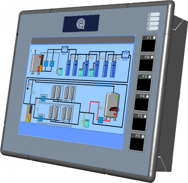
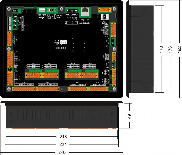

J1-P44-Fx:Installation and Maintenance Manual RMC-1SC01E1/DP1/24Vdc 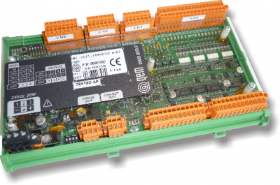
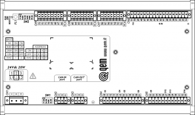
RMC-1SC01:Installation and Maintenance Manual 3.1 Function and LED keys
Key Icon Function Led Key Icon Function Led F1 
Start Cycle - F4 
Semi-automatic = ON Active semi-automatic F2 
Stop Cycle - F5 
Alarm = ON Alarm F3 
Restart - F6 
Exit - - - - - - - - - - - - - - - - - - - - - - - - - - - - - - - - -
3.2 Symbols and keys
Key Description ———————– Top bar symbols Description 
Press to confirm 
Initialization 
Selection 
Emergency 
Previous page 
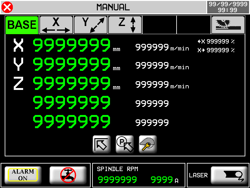
Manual 
Next page 
Homing active 
Reserved area 
Semi-automatic 
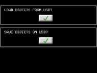
Open file from USB 
Automatic - cycle OFF 
Save 
Automatic - cycle ON 
Working preview 
Calibration mode 
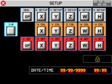
Protected/Unprotected Setup The yellow data is editable 3.3 Startup
START
The instrument waiting the input to be activated
“activated auxiliaries”1) to automatically go
to the next page
Important: pressing the button
you can navigate the HMI, with the machine stationary
HOMING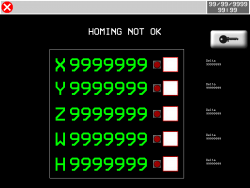
OR
F6
for exit
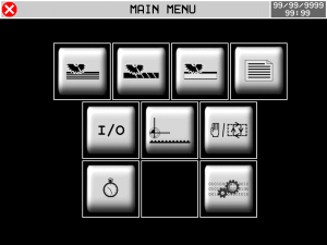
MAIN MENU
1) These are the 24 Volt dc power supplies of the RMC1S modules, limit switches, encoders, relays, etc.4. Main menu
F6 


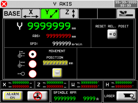
5. Homing
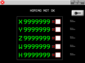

Axis enabled for homing procedure 
Homing OK 
Axis not enabled for homing procedure 
Homing not OK 
Delta error compared to previous homing 
ALWAYS homing before moving to the MANUAL page.
If homing is missing, it affects the functionality of the machine.5.1 Homing procedure
-
Activate the MANUAL
-
Check that there are no ALARMS
-
Select the axes to homing
-
Press START (I10) or F1
-
If the Homings procedure was successful, the green led is turned on
-
If an error occurred during the Homing process, the red is turned on
-
Verify that the error delta (number that appears next to each axis) is = 0 (about)
5.2 Error Delta
This data indicates the Error Delta compared to previous homing, with this value you can easily check if an encoder is good or is broken.
Procedure:
-
Execute an homing 1)
-
Move the axis in manual, numerous times forward and backward
-
Then, without turning off the machine, re-execute the homing
-
The second homing will make it take on an “important” meaning to this number: will show us how much is the offset of the count compared to the actual physical position of the machine
-
If the encoder counts well, this offset must be = 0
-
Then, in practice, this number probably won't always be just = 0 due to the tolerance of limit switch used to do homing
-
Repeating the homing several times, you will be able to realize if the number shows a faulty encoder, or an error given by the tolerance of the limit switch
-
A small error not always repetitive, evidence the tolerance of the limit switch
-
A big error, it will show clearly, a problem to the encoder
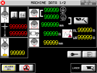
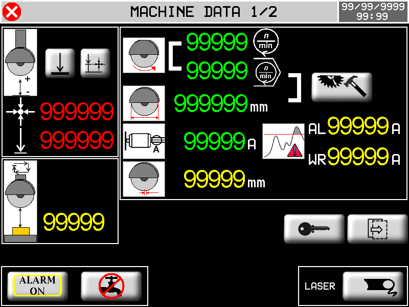
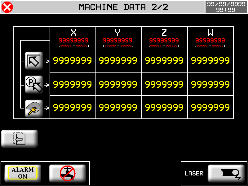
1) The first time you execute an homing (after the instrument is turned on), this number doesn't have a utility6. Machine datas
MAIN MENU


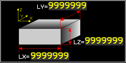
Setting Minimum location Z

Automatic setting Minimum location Z

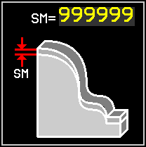
SECURITY QUOTE setting

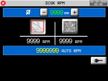
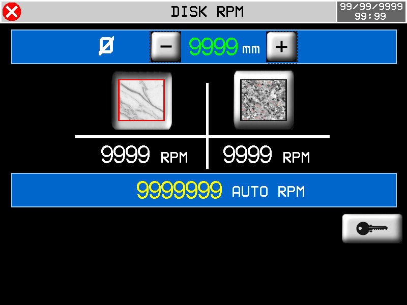
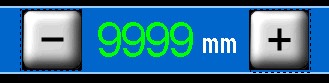
 Disk RPM
  Disk diameter Diameter and RPM setting
  Current Disk Absorption
AL : Maximum current setting
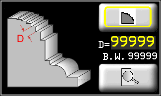
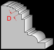
WR : Early warning threshold setting Disk thickness setting
  Out-of-clutter position
  Parking position
  Tool change position
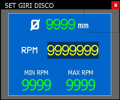
 DISK DIAMETER AND RPM  Disk diameter
  Marble
  Granite
  Automatic RPMs based on disk diameter - Setting an RPM Override
 7. Bottom bar

 : Active Stateflow Alarm
 : Off Stateflow Alarm
  : EV water deactivates
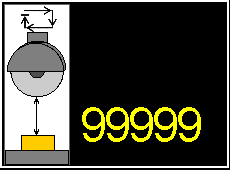
 : EV active water SPINDLE RPM
Ø : Current diameter
RPM : Set the desired rounds
MIN RPM : Minimum setable value
MAX RPM : Maximum setable value99999 A Instantaneous absorption of spindle current. If the WRN symbol appears above the current absorption indication, it means that the pre-alarm threshold has been exceeded.  : EV laser disables
 : EV laser active
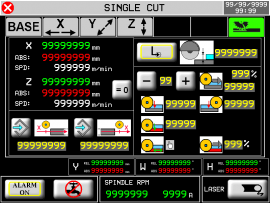
 8. Manual/Semi-Automatic
F6


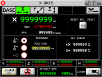


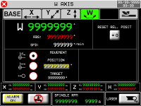


Out-of-clutter position Parking position Tool change position


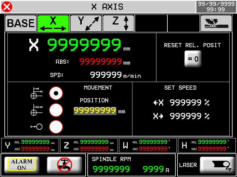
TARGET POSITION SET -  ABSOLUTE TARGET POSITION
- INCREMENTAL TARGET POSITION
- 0 TARGET POSITION
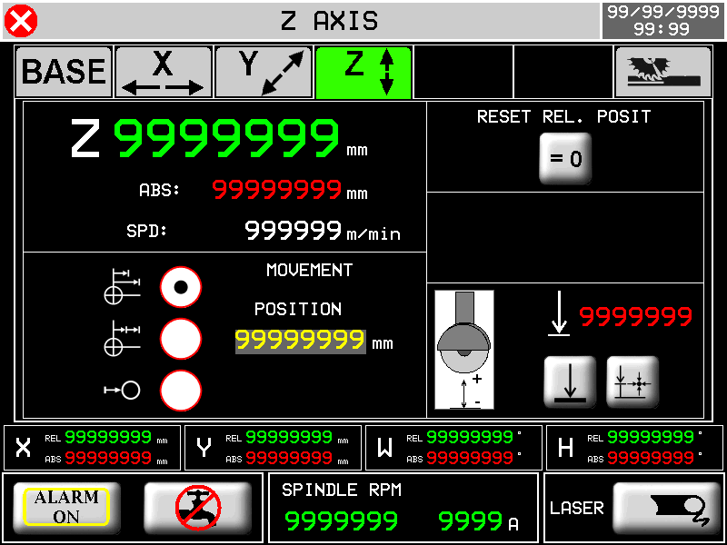
 Reset Relative Position


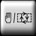
Disk Compensation
 OFF
OFF
 ON
ON 

Minimum Z Position
Z Minimum Position Self-Learning


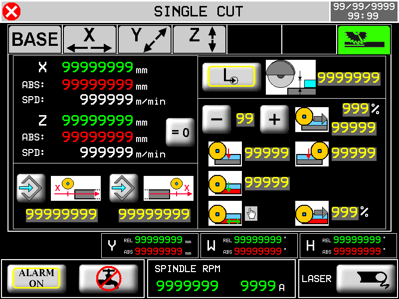
X positions self-learning 
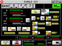
X START Cut Position 
X END Cut position 
Single Pass 
Greek cutting 
Cut Depth Set dati del taglio a greca (max 10)
 01
01 

% Reducing the speed of the first cut 
Forward lowered (X+) 
Backward lowered (X-) Last Cut Direction


Last lowered depth 
% Reducing the speed of the last cut 8.1 Semi-Automatic Execution
-
Check that you are in manual
-
F4 →
-
external START key (I10) or F1
-
the axis reaches the set dimension or single-cut is executed.
9. Reset axes
The reset axes function reset RELATIVE quotas
-
Check you're in manual mode
F3

-
X - : hold to reset the X-axis count
-
Y - : hold to reset the Y-axis count
-
Z - : hold to reset the Z-axis count
-
F6 - Exit from the page
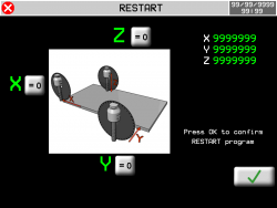
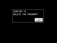
10. Restart working
The restart function restarts the loaded working from the beginning
-
Check that you're in manual mode
-
Check that you're on one of the work pages
F3
in case of cutting slabs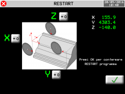
in case of profiling-
OK -
 : press to confirm the restart and exit the page
 -
F6 - Exit from the page without confirmation
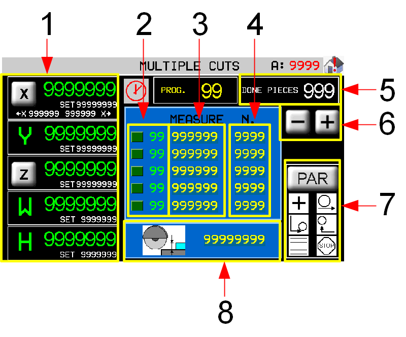
11. Muliple Cuts/Automatic
F6
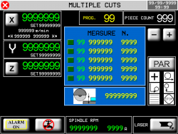


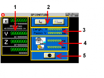
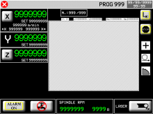
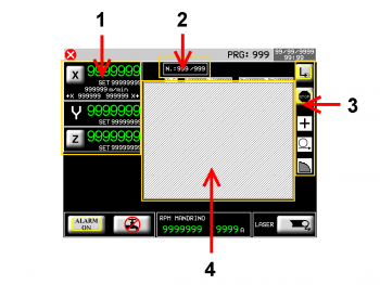
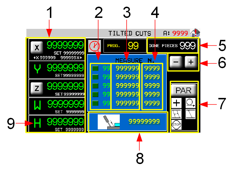
11.0.1 Without table rotation

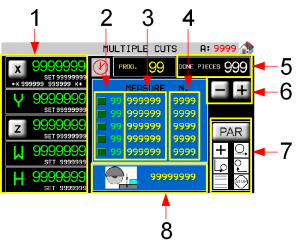
1 Current positions and axis target dimensions
2 Current work step
3 Size of the cut (Y)
4 Number of cuts to be execute
5 Pieces counter
6 Cuts list scroll (1-10)
7 Working parameters
8 Cutting Depth (Z)11.0.2 With table rotation

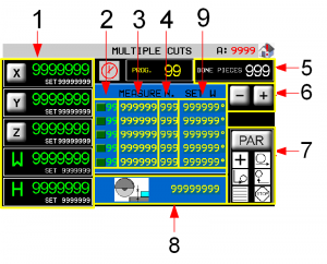
1 Current positions and axis target dimensions
2 Current work step
3 Size of the cut (Y)
4 Number of cuts to be execute
5 Pieces counter
6 Cuts list scroll (1-10)
7 Working parameters
8 Cutting Depth (Z)
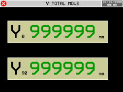
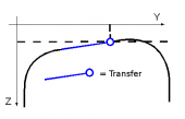
9 Table rotation (W)11.0.3 Y-axis end position page
Pressing on the measurement
the instrument calculates and shows the position of the Y-axis at the end of all moves written in the work schedule + all blade thicknesses.
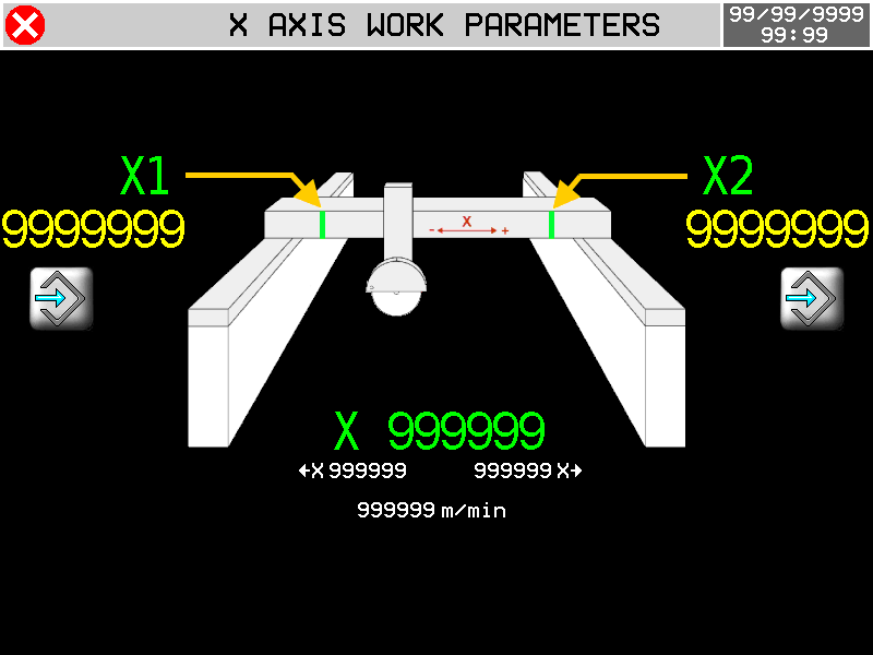
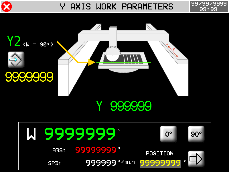
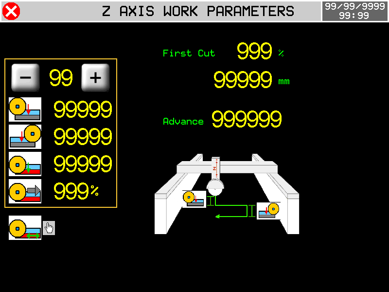
11.0.4 Axes parameters

WITHOUT TABLE ROTATION

WITH TABLE ROTATION
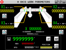
 Self-learning positions X1 + X2 = Table (W) to 0°…..X3 + X4 = Table (W) to 90°
N.B. the disc must exit the slab before learning the X1 - X2 dimensions or X3 - X4 dimensions.
 Self-learning position Y2 = Start position with Table (W) to 90°
 Start of cut X End of cut X W Quick Move the Table 


Immediate position : 0°
Immediate position : 90°
Immediate position set

Input data set
0 ~ 10 Last Cut Direction
Forward lowered (X+) Backward lowered (X-) Last Cut Depth % Reducing last cut speed First cut
% Reducing first cut speed
Position of first increment of passes cut.Advance
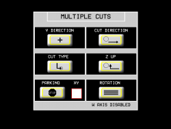
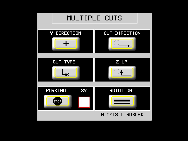
Space before FC software X when Z begins the lowered11.0.5 Working parameters


Y DIRECTION POSITIVE The piece thickness is made with Y that increment

NEGATIVE The piece thickness is made with Y that decrements

CUT DIRECTION X+ Forward only

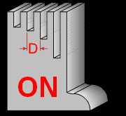
BILATERAL to greek

CUT TYPE SINGLE one pass

TO LOWERED multi-pass

Z LIFT Z lift when X is in the FORWARD POSITION

X and Z come out TOGETHER from the slab

END CYCLE The axes STOPPED when the cycle is end

The disk goes to PARKING at the end of the cycle

XY
X and Y axes in parking one after another
X and Y axes in the parking lot at the same timeROTATION WITHOUT TABLE ROTATION

WITH TABLE ROTATION

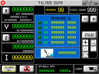
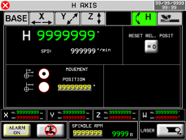
12. Tilted Cuts/Automatic
F6 

H axis without ENCODER

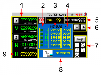
1 Current positions and axis target dimensions
2 Current work step
3 Size of the cut (Y)
4 Number of cuts to be execute
5 Pieces counter
6 Cuts list scroll (1-10)
7 Working parameters
8 Cutting Depth (Z)
9 Settable cut angle (I) Axes parameters - see Multiple Cuts H axis with ENCODER

1 Current positions and axis target dimensions
2 Current work step
3 Size of the cut (Y)
4 Number of cuts to be execute
5 Pieces counter
6 Cuts list scroll (1-10)
7 Working parameters
8 Cutting Depth (Z)
9 Settable cut angle (I) Axes parameters - see Multiple Cuts 12.0.1 Y-axis end position page
Pressing on the measurement
the instrument calculates and shows the position of the Y-axis at the end of all moves written in the work schedule + all blade thicknesses.
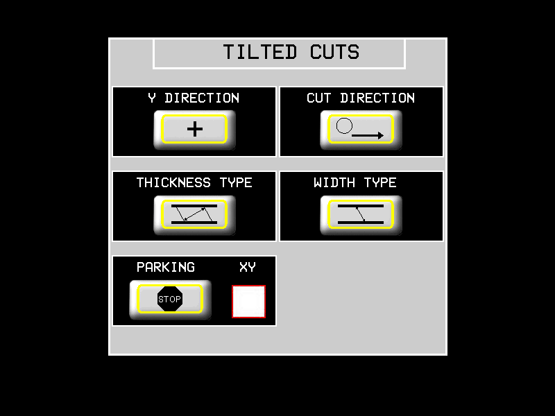
12.0.2 Working parameters

Y DIRECTION POSITIVE The piece thickness is made with Y that increment
NEGATIVE The piece thickness is made with Y that decrements
CUT DIRECTION X+ Forward only
BILATERAL to greek
WIDTH TYPE 90° thickness compared to the cut

PARALLEL thickness to the surface of the plate

DEPTH TYPE Depth = along the disk

Depthà = 90° relative to the surface of the plate

END CYCLE The axes STOPPED when the cycle is end
The disk goes to PARKING at the end of the cycle
XY
X and Y axes in parking one after another
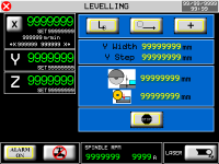
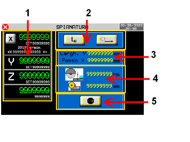
X and Y axes in the parking lot at the same time13. Flattening
 F6
F6


1 Current positions and axis target dimensions
2 Current work step
3 Surface and step width
4 Increment and depth of the cut
5 Parking at the end of working13.0.1 Working parameters
Y width Total width of the part to be flattened. Y step The value of the pitch that covers the Y axis after each cut. Z depth

Cut Depth.
Used if lowered cut is set.Z step

The value of the step that covers the Z axis with each pass.
Used if lowered cut is set.
13.0.2 Axes parameters
Self-learning positions X1 + X2 = Software limit switch of cutting
N.B. the disc must exit the slab before learning the X1 - X2 dimensions
13.0.3 Working parameters
CUT TYPE SINGLE one pass
TO LOWERED multi-pass
CUT DIRECTION X+ Forward only
BILATERAL to greek
Y DIRECTION POSITIVE The move of Y takes place in the positive direction
NEGATIVE The move of Y takes place in the negative direction
END CYCLE The axes STOPPED when the cycle is end
The disk goes to PARKING at the end of the cycle
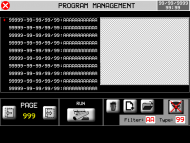
14. Programming and executing profiles
F6


RUN

14.1 Program list filtering
 Using the program list filter you can quickly view the desired program, without scrolling through the entire list. The system has two types of filtering that can be combined together:
-
Program Description Filter
-
Program Type Filter
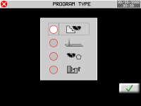
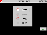
What's a “Program type” :
Type Description 0 Show all programs 1 Show profiling programs only 2 Show milling programs only Not enabled in this version 3 Show cutting polygons programs only Not enabled in this version 14.2 Profiles

 F6
F6


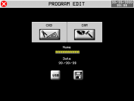

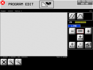


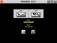
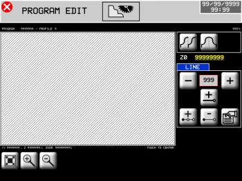
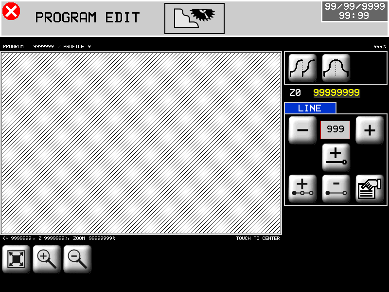
14.2.1 Profiles - CAD


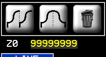
Repeat Shape 
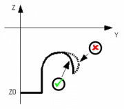
Mirror Shape Z0 = origin
Y Coordinate = 0
Zoom in 
Zoom out 
Fit to screen 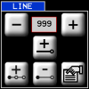
 000
000 
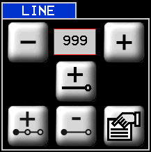
Scroll to choose the stroke you want 
Add a stroke 
Insert a stroke 
Delete a stroke 
Stroke properties


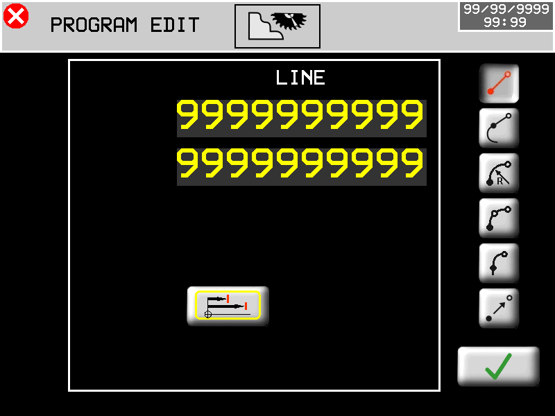
Stroke types 


Absolute
final coordinates are absolute relative to the origin
Incremental
final coordinates are relative to the end of the previous stroke- - - - - - - - - - - - - - - - - - LINE


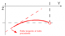
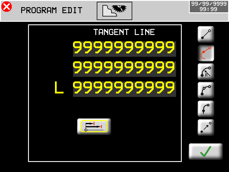
Insert final coordinates TANGENT LINE


Insert Y coordinate 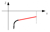
Insert Z coordinate 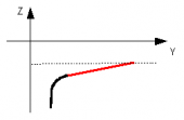
Insert L = length 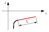
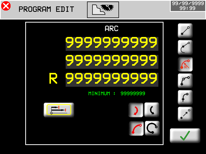
ARC WITH RADIUS


Enter the end coordinates and radius
MINIMUM it's the least radius possible clockwise
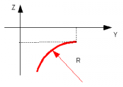
 anticlockwise
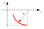
Choosing the direction of the curve
 clockwise OR
  anticlockwise
 short arc OR
  long arc
The program shows the lowest possible radius valueARC FOR 3 POINTS


Insert the coordinates of the endpoint and midpoint
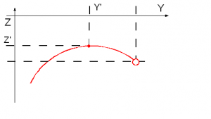
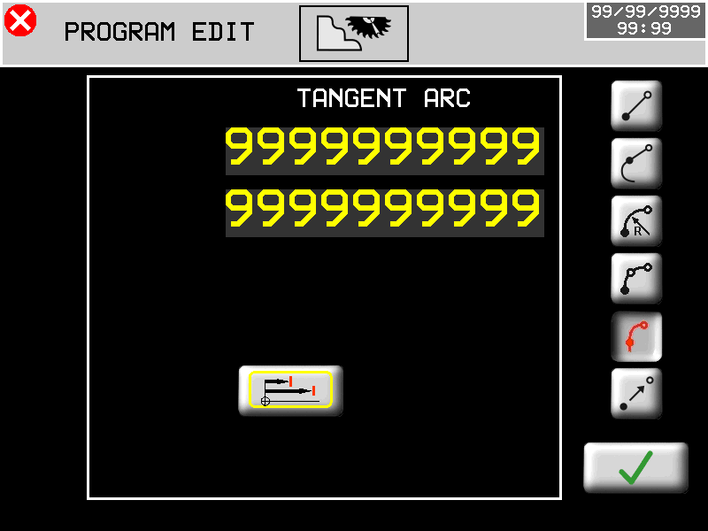
TANGENT ARC


Insert the coordinates of the endpoint
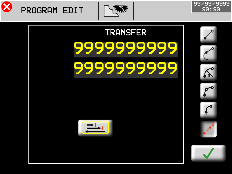
TRANSFER

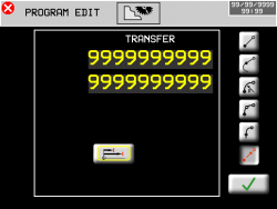
Stroke movement without cuts. Enter end point coordinates
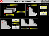
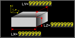
The software automatically corrects the undercut set. 14.2.2 Profiles - parameters


Size of the solid. As an option, you can enter
the size of the solid. This will be grayed out in the
CAD pages of working preview.
Over Material on the profile

Cutting direction only to X+
Bilateral cut
Y-axis increment direction
Distribution of cuts
Strategy type

Disk thickness

Preview cuts


Distribution along the profile


Distribution along the Y-axis
ON: Guaranteed cut on important points


Distribution along the Y-axis
OFF: notable points are not processed
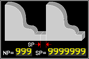
Working repetition
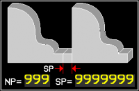
NP = Number of repetitions
SP = Space between repetitions15. Execution
15.1 Program execution
F6

Choose and select the program to preview
RUN


15.1.1 Profile execution
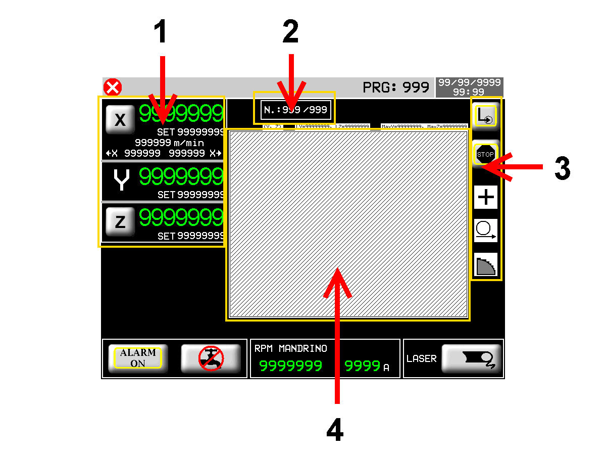
1 Current positions and axis target dimensions
2 Running shape
3 Working parameters
4 Preview of the drawn shape15.1.2 Axis parameters

Self-learning of X1 + X2 positions = Software limit switch of cutting 
Input lowered data set
0 ~ 10 Last cut direction
Forward lowered (X+) Backward lowered (X-) Last Cut Depth % Reducing last cut speed First Cut
% Reducing first cut speedAdvance
Space before FC software X when Z begins the lowered15.1.3 Working parameters
CUT TYPE SINGLE one pass

TO LOWERED multi-pass

END CYCLE The axes STOPPED when the cycle is end

The disk goes to PARKING at the end of the cycle

The following symbols are view-only
They are programmed in the appropriate parameter pages.Y DIRECTION POSITIVE The next cut is done with Y that increments

NEGATIVE The next cut is made with Y that decrements

CUT DIRECTION X+ Forward only

BILATERAL to greek

STRATEGY CUTS ALONG THE PROFILE

CUTS ALONG Y - Notable ON

CUTS ALONG Y - Notable OFF

At the push of the START CYCLE key, the machine starts with the working set.16. Alarms
F5

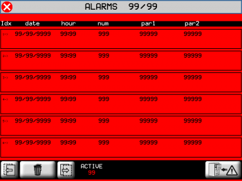

Clear all alarmsThe alarms block all machine operations.
Alarm Cause Solution Emergency Stop for emergency switch - Y axis limit switch FW The Y-axis has encountered the forward limit switch - Y axis limit switch BW The Y-axis has encountered the backrward limit switch - Z axis limit switch UP The Z-axis has encountered the up limit switch - Z axis limit switch DOWN The Z-axis has encountered the down limit switch - X axis limit switch FW The X-axis has encountered the forward limit switch - X axis limit switch BW The X-axis has encountered the backrward limit switch - H axis limit switch FW The H-axis has encountered the forward limit switch - H axis limit switch BW The H-axis has encountered the backrward limit switch - Tool not running The disk must be moving during the automatic cycle - No water pressure Missing of cooling water Control the water flowstate Mandrel motor overcurrent The absorption of the motor disk is over the alarm threshold - No oli pressure Missing of pressure in the lubrication circuit Check the oil flowstate X encoder fault Failure to detect counter Check the encoder Y encoder fault Z encoder fault W encoder fault H encoder fault Thermal outout tripped A thermal drive has been activated - Fault inverters Fault of the axes inverter - Spindle inverter fault Fault of the spindle inverter - CAN module disconnected The remote module does not communicate Check the settings and the cable CAN2 module disconnected X axis out of tolerance Positioning ended out of tolerance Check the axis parameters Y axis out of tolerance Z axis out of tolerance W axis out of tolerance H axis out of tolerance Safety enclosure alarm Perimeter safety protection barriers have been opened - No air pressure Missing of pressure in the air circuit Check the air flowstate Wait for power system… Inactive auxiliary inputs. Communication interrupted with the 2nd RMC1S module at input I74. Activate auxiliary inputs. Check communication with the 2nd RMC1S module. No power system Machine auxiliaries are deactivated - Inverter generic fault Inverters have a non-resetable error Contact the manufacturer of the inverter Bride out of guides Reports that the bridge has lift and the I79 limit switch has intervened. Reset the alarm and bring the bridge back to the binars
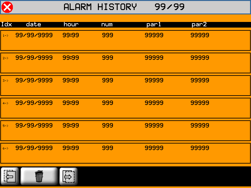
16.1 Alarms list

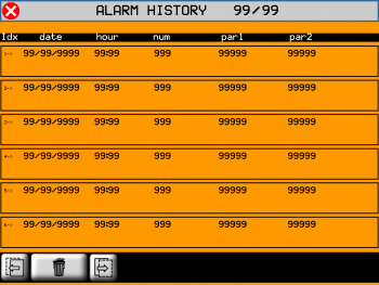 to clear the alarms list
16.2 Messages
The messages do not block machine operations.
Message Cause Solution PLEASE WAIT… Data is being processed - PATH ERROR Error calculating axis path The tool is too wide ERR: TILTED DISK Disk tilt is not compatible with the current working Correct tilt X OVER MAX LIMIT The target dimension of the axis is over the maximum limit switch - Y OVER MAX LIMIT - Z OVER MAX LIMIT - X OVER MIN LIMIT The target dimension of the axis is over the minimum limit switch - Y OVER MIN LIMIT - Z OVER MIN LIMIT - WORK DONE The automatic cycle has successfully ended - X POSITION NOT OK The X position is incorrect The position of X is inside the software limit switches RUN HOMING Homing was not executed Run the procedure NO OBJECT You try to open a non-existent geometry - WAIT FOR START… The working waits for the START command - COMPENSATION ERROR Error calculating disk compensation Check the shape design POWER TOOL ON Start the disk to start the cycle - Y OVER MAX/MIN LIMIT Processing data requires a Y movement beyond software limits - BRIDGE OUT OF RAIL The bridge is lifted See Alarm Reporting Description 17. Diagnostic
F6


PASSWORD:462
I/O

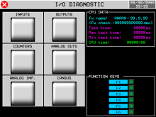
INPUTS

OUTPUTS
COUNTERS
ANALOG OUTS
ANALOG INP.

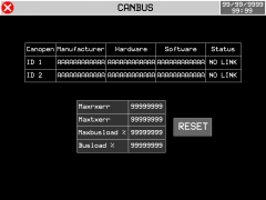
CANBUS
17.1 CPU DATA
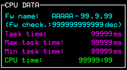
Fw name : firmware code and checksum
Task time : average time of CPU cycle
Maximum Time and Minimum Time registered limits
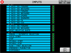
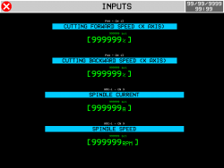
CPU time : total CPU time in RUN state (hh:mm)17.2 Digital inputs
INPUTS


Status of digital inputs
 = OFF
= OFF
= ONPrevious page Next page
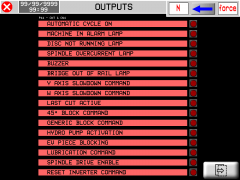
17.3 Digital outputs
OUTPUTS
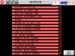
Status of digital outputs
= OFF
 = ON
= ON Previous page Next page 
Press to switch to output force mode
Press the output that you want to activate.
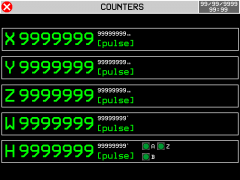
17.4 Encoder counters
COUNTERS

Axes position

Status of encoder channels
= OFF
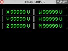
= ON 17.5 Analog outputs
ANALOG OUTS
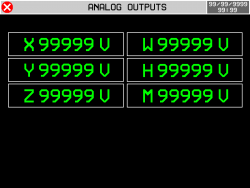
Analog outputs voltage
17.6 Analog inputs
ANALOG INP.
Analog inputs read
17.7 Communication with RMC1S modules
CANBUS

Status of communication with RMC1S modules. 18. Assistance
For supplying you fast service, at the lowest cost, we need your support.

Follow all instructions provided in the MIMAT manual If the problem remains, fill out the “Request Form for assistance” on the page Contacts at www.qem.it site.
Our technicians will get elements essential for the understanding of your problem.Repair
To provide you with an efficient service, please read and adhere to the instructions given here
Shipping
It is recommended to pack the instrument with materials that are able to cushion any falls.


Use the original package: it must protect the instrument during transport. Attach:
1. A description of the anomaly;
2. A part of the electric scheme where the equipment is inserted
3. The planning of the equipment (set up, quotas of job, parameters…).
4. Request a quote for repair; if not required, the cost will be calculated in the final balance.A full description of the problem, will help identify and resolve your problems fast. A careful packaging will avoid further inconveniences. -


- Last modified: 2021/04/22 12:59