Multi-head Polishing Machine: Connections
Description
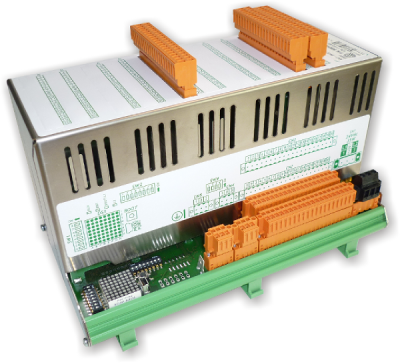
The P1P51FC20-008 application, installed on the hardware Qmove+ J1-P51-FC20 e I/O modules RMC-2M, has been developed to control double mobile bridge, multi-head polishing machine for marble slaps.
| Document | P1P51FC20-008 | ||
|---|---|---|---|
| Description | Connections | ||
| Drawn up | Riccardo Furlato | ||
| Approved | Gabriele Bazzi | ||
| Link: | http://www.qem.eu/doku/doku.php/en/strumenti/qmoveplus/j1p51/mdu_p1p51fc20-008/connections | ||
| Languages | English | ||
| Release | Description | Notes | Date |
| 01 | New Manual | 03/06/14 | |
All rights reserved on this manual. No part of this document can be copied or reproduced in any form without prior written authorisation. QEM does not insure or guarantee its contents and explicitly declines all liability related to the guarantee of its suitability for any purpose. The information in this document can be changed without notice. QEM shall not be held liable for any error or omission in this document. QEM® is a registered trademark.Microsoft® and MS-DOS® are registered trademarks and Windows® is a trademark of Microsoft Corporation.
Hardware
Operator Panel
| J1-P51-FC20/TP03 |
|---|
 |
 |
Remote modules inputs/outputs
| [1] Cabinet :RMC-2MC01-D2/I32/I32/I32/0/0/24V [2] Bridge 1 :RMC-2MC01-G5/A12/0/AP2/P32/0/24V [3] Bridge 2 :RMC-2MC01-G5/A12/0/AP2/P32/0/24V |
|---|
 |
 |
I/O Resources
Digital Inputs (n. 181)
| Name | Description | Terminal | Terminal Block | Hardware |
|---|---|---|---|---|
| I01 | Emergency | CN11 | J1-P51 | |
| I02 | Bridge: Forward Jog | |||
| I03 | Bridge: Backward Jog | |||
| I04 | START pushbutton | |||
| I05 | STOP pushbutton | |||
| I06 | Change Abrasive pushbutton | |||
| I07 | MAN / AUTO selector | |||
| I08 | STAND-BY | |||
| I09 | Heads: cutouts | CN12 | ||
| I10 | Bridge 1: Fault | |||
| I11 | Bridge 2: Fault | |||
| I12 | Belt: Fault | |||
| I13 | Roller: Fault | |||
| I14 | Air Pressure | |||
| I15 | Water Pressure | |||
| I16 | Bridge: Forward LS | |||
| I17 | Bridge: Backward LS | CN13 | ||
| I18 | Bridge: Zero sensor | |||
| I19 | Roller: Slab sensor at end | |||
| I20 | Belt: Slab sensor at start | |||
| I21 | Change abrasive sensor | |||
| I22 | Not used | |||
| I23 | Not used | |||
| I24 | Not used | |||
| I25 | Not used | CN14 | ||
| I26 | Not used | |||
| I27 | Not used | |||
| I28 | Not used | |||
| I29 | Not used | |||
| I30 | Not used | |||
| I31 | Not used | |||
| I32 | Not used | |||
| Name | Description | Terminal | Terminal Block | Hardware |
|---|---|---|---|---|
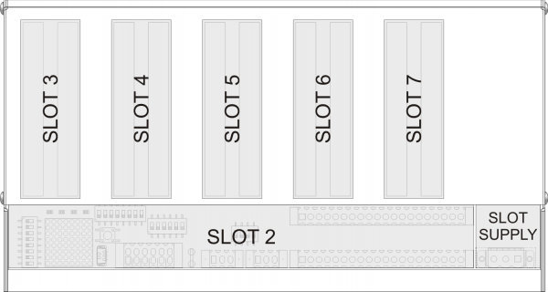
| I33 | Head-1: Local Man/Aut | SLOT 2 | RMC-2M [1]cabinet |
|
| I34 | Head-1: Local Jog | |||
| I35 | Head-2: Local Man/Aut | |||
| I36 | Head-2: Local Jog | |||
| I37 | Head-3: Local Man/Aut | |||
| I38 | Head-3: Local Jog | |||
| I39 | Head-4: Local Man/Aut | |||
| I40 | Head-4: Local Jog | |||
| I41 | Head-5: Local Man/Aut | |||
| I42 | Head-5: Local Jog | |||
| I43 | Head-6: Local Man/Aut | |||
| I44 | Head-6: Local Jog | |||
| I45 | Head-7: Local Man/Aut | |||
| I46 | Head-7: Local Jog | |||
| I47 | Head-8: Local Man/Aut | |||
| I48 | Head-8: Local Jog | |||
| I49 | Head-9: Local Man/Aut | |||
| I50 | Head-9: Local Jog | |||
| I51 | Head-10: Local Man/Aut | |||
| I52 | Head-10: Local Jog | |||
| I53 | Head-11: Local Man/Aut | |||
| I54 | Head-11: Local Jog | |||
| I55 | Head-12: Local Man/Aut | |||
| I56 | Head-12: Local Jog | |||
| I57 | Head-13: Local Man/Aut | |||
| I58 | Head-13: Local Jog | |||
| I59 | Head-14: Local Man/Aut | |||
| I60 | Head-14: Local Jog | |||
| I61 | Head-15: Local Man/Aut | |||
| I62 | Head-15: Local Jog | |||
| I63 | Head-16: Local Man/Aut | |||
| I64 | Head-16: Local Jog | |||
| I65 | Head-17: Local Man/Aut | SLOT 3 (I32) | ||
| I66 | Head-17: Local Jog | |||
| I67 | Head-18: Local Man/Aut | |||
| I68 | Head-18: Local Jog | |||
| I69 | Head-19: Local Man/Aut | |||
| I70 | Head-19: Local Jog | |||
| I71 | Head-20 Local Man/Aut | |||
| I72 | Head-20 Local Man/Aut | |||
| I73 | Head-21: Local Man/Aut | |||
| I74 | Head-21: Local Jog | |||
| I75 | Head-22: Local Man/Aut | |||
| I76 | Head-22: Local Jog | |||
| I77 | Head-23: Local Man/Aut | |||
| I78 | Head-23: Local Jog | |||
| I79 | Head-24: Local Man/Aut | |||
| I80 | Head-24: Local Jog | |||
| I81 | Not used | |||
| I82 | Not used | |||
| I83 | Not used | |||
| I84 | Not used | |||
| I85 | Not used | |||
| I86 | Not used | |||
| I87 | Not used | |||
| I88 | Not used | |||
| I89 | Not used | |||
| I90 | Not used | |||
| I91 | Not used | |||
| I92 | Not used | |||
| I93 | Not used | |||
| I94 | Not used | |||
| I95 | Not used | |||
| I96 | Not used | |||
| Name | Description | Terminal | Terminal Block | Hardware |
|---|---|---|---|---|
| I97 | Bar sensor 1 | SLOT4 (I32) | RMC-2M [1]cabinet |
|
| I98 | Bar sensor 2 | |||
| I99 | Bar sensor 3 | |||
| I100 | Bar sensor 4 | |||
| I101 | Bar sensor 5 | |||
| I102 | Bar sensor 6 | |||
| I103 | Bar sensor 7 | |||
| I104 | Bar sensor 8 | |||
| I105 | Bar sensor 9 | |||
| I106 | Bar sensor 10 | |||
| I107 | Bar sensor 11 | |||
| I108 | Bar sensor 12 | |||
| I109 | Bar sensor 13 | |||
| I110 | Bar sensor 14 | |||
| I111 | Bar sensor 15 | |||
| I112 | Bar sensor 16 | |||
| I113 | Bar sensor 17 | |||
| I114 | Bar sensor 18 | |||
| I115 | Bar sensor 19 | |||
| I116 | Bar sensor 20 | |||
| I117 | Bar sensor 21 | |||
| I118 | Bar sensor 22 | |||
| I119 | Bar sensor 23 | |||
| I120 | Bar sensor 24 | |||
| I121 | Bar sensor 25 | |||
| I122 | Bar sensor 26 | |||
| I123 | Bar sensor 27 | |||
| I124 | Bar sensor 28 | |||
| I125 | Bar sensor 29 | |||
| I126 | Bar sensor 30 | |||
| I127 | Bar sensor 31 | |||
| I128 | Bar sensor 32 | |||
| I129 | Bar sensor 33 | SLOT5 (I32) | RMC-2M [1]cabinet |
|
| I130 | Bar sensor 34 | |||
| I131 | Bar sensor 35 | |||
| I132 | Bar sensor 36 | |||
| I133 | Bar sensor 37 | |||
| I134 | Bar sensor 38 | |||
| I135 | Bar sensor 39 | |||
| I136 | Bar sensor 40 | |||
| I137 | Bar sensor 41 | |||
| I138 | Bar sensor 42 | |||
| I139 | Bar sensor 43 | |||
| I140 | Bar sensor 44 | |||
| I141 | Bar sensor 45 | |||
| I142 | Bar sensor 46 | |||
| I143 | Bar sensor 47 | |||
| I144 | Bar sensor 48 | |||
| I145 | Bar sensor 49 | |||
| I146 | Bar sensor 50 | |||
| I147 | Bar sensor 51 | |||
| I148 | Bar sensor 52 | |||
| I149 | Bar sensor 53 | |||
| I150 | Bar sensor 54 | |||
| I151 | Bar sensor 55 | |||
| I152 | Bar sensor 56 | |||
| I153 | Bar sensor 57 | |||
| I154 | Bar sensor 58 | |||
| I155 | Bar sensor 59 | |||
| I156 | Bar sensor 60 | |||
| I157 | Bar sensor 61 | |||
| I158 | Bar sensor 62 | |||
| I159 | Bar sensor 63 | |||
| I160 | Bar sensor 64 | |||
| Name | Description | Terminal | Terminal Block | Hardware |
|---|---|---|---|---|
| I161.. | Not used | SLOT 2 | RMC-2M [2]bridge 1 |
|
| ..I192 | Not used | |||
| Name | Description | Terminal | Terminal Block | Hardware |
|---|---|---|---|---|
| I193.. | Not used | SLOT 2 | RMC-2M [3]bridge 2 |
|
| ..I224 | Not used | |||
Digital Outputs (n. 88)
| Name | Description | Terminal | Terminal Block | Hardware |
|---|---|---|---|---|
| O1 | AUTOMATIC ON light | CN7 | J1-P51 | |
| O2 | ALARM light | |||
| O3 | PRE-START light | |||
| O4 | RUN light | |||
| O5 | Bridge enable | |||
| O6 | Belt start | |||
| O7 | Roller start | |||
| O8 | Brush Up/Down | |||
| O9 | Upline machine consensus | CN8 | J1-P51 | |
| O10 | Lubrication | |||
| O11 | Belt stop | |||
| O12 | Spray On/Off | |||
| O13 | Not used | |||
| O14 | Not used | |||
| O15 | Not used | |||
| O16 | Not used | |||
| Name | Description | Terminal | Terminal Block | Hardware |
|---|---|---|---|---|
| O24 | Head 1: Start | SLOT3 (P32) | RMC-2M/bridge | |
| O25 | Head 1: Up | |||
| O26 | Head 1: Down | |||
| O27 | Head 2: Start | |||
| O28 | Head 2: Up | |||
| O29 | Head 2: Down | |||
| O30 | Head 3: Start | |||
| O31 | Head 3: Up | |||
| O32 | Head 3: Down | |||
| O33 | Head 4: Start | |||
| O34 | Head 4: Up | |||
| O35 | Head 4: Down | |||
| O36 | Head 5: Start | |||
| O37 | Head 5: Up | |||
| O38 | Head 5: Down | |||
| O39 | Head 6: Start | |||
| O40 | Head 6: Up | |||
| O41 | Head 6: Down | |||
| O42 | Head 7: Start | |||
| O43 | Head 7: Up | |||
| O44 | Head 7: Down | |||
| O45 | Head 8: Start | |||
| O46 | Head 8: Up | |||
| O47 | Head 8: Down | |||
| O48 | Head 9: Start | |||
| O49 | Head 9: Up | |||
| O50 | Head 9: Down | |||
| O51 | Head 10: Start | |||
| O52 | Head 10: Up | |||
| O53 | Head 10: Down | |||
| O54 | Head 11: Start | |||
| O55 | Head 11: Up | |||
| O56 | Head 11: Down | SLOT4 (P32) | RMC-2M/bridge | |
| O57 | Head 12: Start | |||
| O58 | Head 12: Up | |||
| O59 | Head 12: Down | |||
| O60 | Head 13: Start | |||
| O61 | Head 13: Up | |||
| O62 | Head 13: Down | |||
| O63 | Head 14: Start | |||
| O64 | Head 14: Up | |||
| O65 | Head 14: Down | |||
| O66 | Head 15: Start | |||
| O67 | Head 15: Up | |||
| O68 | Head 15: Down | |||
| O69 | Head 16: Start | |||
| O70 | Head 16: Up | |||
| O71 | Head 16: Down | |||
| O72 | Head 17: Start | |||
| O73 | Head 17: Up | |||
| O74 | Head 17: Down | |||
| O75 | Head 18: Start | |||
| O76 | Head 18: Up | |||
| O77 | Head 18: Down | |||
| O78 | Head 19: Start | |||
| O79 | Head 19: Up | |||
| O80 | Head 19: Down | |||
| O81 | Head 20: Start | |||
| O82 | Head 20: Up | |||
| O83 | Head 20: Down | |||
| O84 | Head 21: Start | |||
| O85 | Head 21: Up | |||
| O86 | Head 21: Down | |||
| O87 | Not used | |||
| O88 | Not used | |||
 che facciamo per le 3x uscite di teste 22-23-24 = totale 9 uscite
Two-way Count Inputs (n. 3)
| Name | Description | Terminal | Terminal Block | Hardware |
|---|---|---|---|---|
| PHA1 PHB1 | Bridge | CN15 | J1-P51 | |
| PHA2 PHB2 | Belt1 | CN16 | ||
| PHA3 PHB3 | Belt2 | CN16 | ||
Analog Inputs (n. 26)
| Name | Description | Terminal block | Hardware | |
|---|---|---|---|---|
| AI1 | Not used | CN28 | J1-P51 | |
| AI2 | Not used | |||
| Name | Description | Terminal | Terminal Block | Hardware |
|---|---|---|---|---|
| AI3 | Abrasive Wear Head-1 | SLOT 5 (AR2) | RMC-2M/bridge | |
| AI4 | Abrasive Wear Head-2 | |||
| AI5 | Abrasive Wear Head-3 | |||
| AI6 | Abrasive Wear Head-4 | |||
| AI7 | Abrasive Wear Head-5 | |||
| AI8 | Abrasive Wear Head-6 | |||
| AI9 | Abrasive Wear Head-7 | |||
| AI10 | Abrasive Wear Head-8 | |||
| AI11 | Abrasive Wear Head-9 | SLOT 6 (AR2) | RMC-2M/bridge | |
| AI12 | Abrasive Wear Head-10 | |||
| AI13 | Abrasive Wear Head-11 | |||
| AI14 | Abrasive Wear Head-12 | |||
| AI15 | Abrasive Wear Head-13 | |||
| AI16 | Abrasive Wear Head-14 | |||
| AI17 | Abrasive Wear Head-15 | |||
| AI18 | Abrasive Wear Head-16 | |||
| AI19 | Abrasive Wear Head-17 | SLOT 7 (AR2) | RMC-2M/bridge | |
| AI20 | Abrasive Wear Head-18 | |||
| AI21 | Abrasive Wear Head-19 | |||
| AI22 | Abrasive Wear Head-20 | |||
| AI23 | Abrasive Wear Head-21 | |||
| AI24 | Abrasive Wear Head-22 | |||
| AI25 | Abrasive Wear Head-23 | |||
| AI26 | Abrasive Wear Head-24 | |||
Analog outputs (n. 3)
| Name | Description | Terminal | Terminal Block | Hardware |
|---|---|---|---|---|
| AO1 | Bridge speed control ±10Vdc | CN26 | J1-P51 | |
| AO2 | Belt1 speed control ±10Vdc | |||
| AO3 | Belt2 speed control ±10Vdc | |||
| AO4 | Not used | |||
Electrical Connections
Standard Hardware manuals
J1-P51 FD20 link to manual: http://www.qem.eu/doku/doku.php/en/strumenti/qmoveplus/j1p51/mimj1p51fx_full
RMC 2M link to manual:
Setup
Access to setup
 |  password 462 |  |
SETUP groups
 general parameters general parameters |  bridge parameters bridge parameters |
 head parameters head parameters |  sensor bar parameters sensor bar parameters |
General Setup

| Parameter | Unit measure | Default | Range | Description |
|---|---|---|---|---|
| PG01 : LANGUAGE | - | ITA | 1 - 2 | 1: ITALIAN 2: ENGLISH |
| PG03 : DECIMAL POINT | - | 1 | 0 – 3 | How many decimals are shown |
| PG05 : HORIZONTAL STEP | mm | 50.0 | - | Linear read spacing. Distance between the reading the Sensor bar state |
| PG06 : VERTICAL STEP | mm | 50.0 | - | Transverse read spacing. Distance between the photocells on the Sensor bar |
| PG08 : LINE MEASURE | mm | 1 | 0 – 999999 | The distance, in unit measures, made by the belt for the encoder pulses set at parameter, pulse. |
| PG09 : LINE PULSE | - | 1 | 0 - 999999 | The pulses supplied by the bridge encoder, multiplied by 4, to obtain the distance, set at the parameter measure. The measure to pulse ratio is the encoder resolution and must be between 1 and 0.000935 |
| PG11 : BRIDGE SELF-LEARN | - | OFF | 0 – 1 | Enable the self-learn option on the minimum and maximum quotas of the slab, to optimise the bridge strokes. |
| PG13 : OPERATOR SIDE | - | FWD | 0 – 1 | The bridge position, when the cycle is stopped FWD = at the maximum position, BWD = at the minimum position |
| PG15 : SELECTOR AUTO/MAN | - | ON | 0 – 1 | Enable manual/automatic selector. |
| PG16 : TIME PRE-START | s | 3.0 | 0 – 9999.9 | Time after start command for effective startup of the machine (there is a warning during this time). If less that motor startup time, the greater is counted. |
| PG17 : LUBR. TIME ON | s | 0.0 | 0 – 9999.9 | Lubrication time. |
| PG18 : LUBR. TIME OFF | s | 0.0 | 0 – 9999.9 | Lubrication off time. |
| PG19 : MOTOR TIME ON | s | 1.000 | 0 – 99.999 | Delay time between the startup of one motor and another (startup sequence) |
| PG20 : MOTOR TIME OFF | s | 0.200 | 0 – 99.999 | Delay time between the shutoff of one motor and another (stop sequence) |
| PG21 : MOTOR TIME OFF ON EXIT BELT | s | 0.000 | 0 – 99.999 | Delay time before the shutoff sequence of the motors, from when no slabs are on the belt |
| PG25 : HEADS OUTPUT | - | CONST | CONST – PULSE | Head operating mode CONST = always activated when the heads are operating PULSE = activated for a set time (PG27). |
| PG26 : LINE OUTPUT | - | CONST | CONST – PULSE | Belt operating mode. CONST = always activated when the belt is operating PULSE = activated for a set time (PG27). |
| PG27 : PULSE TIME | s | 0.000 | 0 - 99.999 | Head and belt activation time, if operation set to PULSE |
| PG28 : LINE DELAY | s | 0.000 | 0 – 99.999 | Delay time for belt start, after the belt start |
| PG30 : BRUSH ADVANCE | mm | 0.0 | -9999.9 – 9999.9 | Anticipate distance for brush down |
| PG31 : BRUSH DELAY | mm | 0.0 | -9999.9 – 9999.9 | Delay distance for brush up |
| PG32 : REF. SPEED | m/' | 0.0 | 0 – 9999.9 | Reference speed for the brush early and delay 0 = proportional speed, but constant set distances |
Bridge Setup

| Parameter name | Unit measure | Default | Range | Description |
|---|---|---|---|---|
| PB01 : MEASURE | mm | 0.1 | 0 – 99999.9 | The space, in the unit measure, travelled by the bridge to obtain the encoder pulses, set at the parameter pulse. |
| PB02 : PULSE | - | 1 | 0 – 999999 | The pulses supplied by the bridge encoder, multiplied by 4 to obtain the space, set at the parameter measure. The measure to pulse ratio, is the encoder resolution and must be between 1 and 0.000935. |
| PB03 : TOLERANCE | mm | 5.0 | 0 – 99999.9 | The maximum deviation of the count around the positioning quotas, for it to be considered correct |
| PB04 : ENABLE TIME | s | 0.200 | 0.000 – 9.999 | Time before starting the bridge movement |
| PB05 : DISABLE TIME | s | 0.200 | 0.000 – 9.999 | Time after ending the the bridge movement |
| PB06 : MAXPOS | mm | 99999.9 | -99999.9 – 99999.9 | Maximum height of the bridge |
| PB07 : MINPOS | mm | -99999.9 | -99999.9 – 99999.9 | Minimum height of the bridge |
| PB08 : ACCELERATION TIME | s | 1.00 | 0.00 – 9.99 | The time needed to go from 0 speed to maximum speed |
| PB09 : DECELERATION TIME | s | 1.00 | 0.00 – 9.99 | The time needed to go from maximum speed to 0 speed |
| PB10 : INVERSION TIME | s | 0.50 | 0.00 – 9.99 | Protection against mechanical stress, caused by rapid changes in direction |
| PB11 : DISACTIVATIO TIME | s | 0 | 0 – 99999 | Maximum delay time for the bridge, before the axis enable output is disactivated |
| PB12 : OUTPUT MODE | - | STILL | MOVE, STILL | Enable mode for the axis output MOVE: The output is activated before the axis movement and disactivated at the end, according to the times set at the parameters PB04 and PB05 STILL: The output is activated before the axis movement and disactivated only when in emergency |
| PB14 : PRESET POSITION | mm | 0.0 | -99999.9 – 99999.9 | Axis Homing position |
| PB15 : PRESET SPEED | % | 5 | 1 – 100 | Axis speed, when searching for the homing sensor |
| PB16 : PRESET SLOW SPEED | % | 2 | 1 – 100 | Speed for disengaging the homing sensor. |
| PB17 : PRESET DIRECTION | - | FORWARD | FORWARD, BACKWARD | Axis direction, when searching for the homing sensor |
| PB19 : CHANGE ABR POSITION | mm | 0.0 | -99999.9 – 99999.9 | Bridge positioning quota, when the cycle is stopped to change abrasive |
Calibrations
 | Axis resolution settings |
 | Axis calibration procedure, for feedback, offset and maximum speed |


Heads Setup

| Parameter | Unit measure | Default | Range | Description |
|---|---|---|---|---|
| PT01 / PT22 : DIAMETER | mm | 0.0 | 0 – 99999.9 | Head diameter |
| PT23 / PT44 : VERTICAL OFFSET | mm | 0.0 | 0 – 99999.9 | Distance from the head and central point of the bridge |
| PT45 / PT66 : STANDY UP TIME | s | 0.500 | 0 – 999.999 | The up movement time for the standby up |
| PT67 : BRAKE MODE | - | Out Off Brake activated | Out Off - Out On Brake activated | Brake output state when activated |
| PT68 : UP DELAY | s | 0.000 | 0 – 999.999 | Delay time for the total up of the heads |
Sensors Setup

| Parameter | Unità di misura | Default | Range | Description |
|---|---|---|---|---|
| PS01 : NUMBER OF SENSORS | - | 32 | 8 – 64 | Number of sensors on the Sensor Bar |
| PS02 : PHOTOCELL TYPE | - | NO | NO – NC | Slab acquisition input logic NO = Normally Open NC = Normally Closed |