This is an old revision of the document!
Specialization card 1MG6F rel.03

Informations
| |
||||
| Document: | MIM1MG6F03 | |||
|---|---|---|---|---|
| Description: | Installation and maintenance manual | |||
| Editor: | Riccardo Furlato | |||
| Approver | Gabriele Bazzi | |||
| Link: | http://www.qem.eu/doku/doku.php/strumenti/qmoveplus/mim1mg6f03 | |||
| Language: | English | |||
| Document release | Hardware release | Description | Note | Date |
| 00 | 03 | The step-direction voltage now are settable | 10/02/2016 | |
1. Description
The 1MG6F card for the Qmove+ series.
1.1 Equipment
 | 32 standard digital inputs (+12 alternative inputs to 6 counters) |
 | 4 analog inputs |
 | 4 rapid digital inputs |
 | 6 bidirectional counters |
 | 2 SSI absolute counters |
 | 32 digital outputs |
 | 8 analog outputs |
 | 5 step-direction outputs |
2. Connectors
2.1 Digital inputs
2.1.1 32 standard digital inputs + 4 rapid inputs
 | The electrical features are given in paragraph Electrical Features. The wiring examples are given in paragraph Connection examples |
|---|
| CN11 | Terminal | Symbol | Description | Address | |
|---|---|---|---|---|---|
 | 1 | I01(PNP) | PNP type fast input I01 | External terminal configuration1) | FREQ12) |
| 2 | I01(NPN) | PNP type fast input I01 | |||
| 3 | 0V | Common for digital inputs | |||
| 4 | I1 | Input I1 | 3.INP01 | ||
| 5 | I2 | Input I2 | 3.INP02 | ||
| 6 | I3 | Input I3 | 3.INP03 | ||
| 7 | I4 | Input I4 | 3.INP04 | ||
| 8 | I5 | Input I5 | 3.INP05 | ||
| 9 | I6 | Input I6 | 3.INP06 | ||
| 10 | I7 | Input I7 | 3.INP07 | ||
| 11 | I8 | Input I8 | 3.INP08 | ||
| 12 | 0V | Common for digital inputs | |||
| CN12 | Terminal | Symbol | Description | Address | |
|---|---|---|---|---|---|
| | 1 | I02(PNP) | PNP type fast input I02 | External terminal configuration1) | FREQ22) |
| 2 | I02(NPN) | NPN type fast input I02 | |||
| 3 | 0V | Common for digital inputs | |||
| 4 | I9 | Input I9 | 3.INP09 | ||
| 5 | I10 | Input I10 | 3.INP10 | ||
| 6 | I11 | Input I11 | 3.INP11 | ||
| 7 | I12 | Input I12 | 3.INP12 | ||
| 8 | I13 | Input I13 | 3.INP13 | ||
| 9 | I14 | Input I14 | 3.INP14 | ||
| 10 | I15 | Input I15 | 3.INP15 | ||
| 11 | I16 | Input I16 | 3.INP16 | ||
| 12 | 0V | Common for digital inputs | |||
| CN13 | Terminal | Symbol | Description | Address | |
|---|---|---|---|---|---|
| | 1 | I03(PNP) | PNP type fast input I03 | External terminal configuration1) | 1.INT09 |
| 2 | I03(NPN) | NPN type fast input I03 | |||
| 3 | 0V | Common for digital inputs | |||
| 4 | I17 | Input I17 | 3.INP17 | ||
| 5 | I18 | Input I18 | 3.INP18 | ||
| 6 | I19 | Input I19 | 3.INP19 | ||
| 7 | I20 | Input I20 | 3.INP20 | ||
| 8 | I21 | Input I21 | 3.INP21 | ||
| 9 | I22 | Input I22 | 3.INP22 | ||
| 10 | I23 | Input I23 | 3.INP23 | ||
| 11 | I24 | Input I24 | 3.INP24 | ||
| 12 | 0V | Common for digital inputs | |||
Terminal 1: connect to 12-24Vdc of the power unit
Terminal 2: input
PNP type fast input configuration:
Terminal 1: input
Terminal 2: connect to 0V (terminal 3)
| CN14 | Terminal | Symbol | Description | Address | |
|---|---|---|---|---|---|
| | 1 | I04(PNP) | PNP type fast input I04 | External terminal configuration1) | 1.INT10 |
| 2 | I04(NPN) | NPN type fast input I04 | |||
| 3 | 0V | Common for digital inputs | |||
| 4 | I25 | Input I25 | 3.INP25 | ||
| 5 | I26 | Input I26 | 3.INP26 | ||
| 6 | I27 | Input I27 | 3.INP27 | ||
| 7 | I28 | Input I28 | 3.INP28 | ||
| 8 | I29 | Input I29 | 3.INP29 | ||
| 9 | I30 | Input I30 | 3.INP30 | ||
| 10 | I31 | Input I31 | 3.INP31 | ||
| 11 | I32 | Input I32 | 3.INP32 | ||
| 12 | 0V | Common for digital inputs | |||
Terminal 1: connect to 12-24Vdc of the power unit
Terminal 2: input
PNP type fast input configuration:
Terminal 1: input
Terminal 2: connect to 0V (terminal 3)
2.1.2 6 bidirectional counter inputs 200KHz
| The electrical features are given in paragraph Electrical features. The wiring examples are given in paragraph Connection examples |
|---|
| CN15 | Terminal | Symbol | Description | Address | ||
|---|---|---|---|---|---|---|
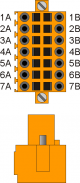 | 1A | Internal bridge 1A -1B | ||||
| 2A | PHA1 | Phase A count 1 | PNP Push-Pull1) | 3.INP33 | 3.CNT01 | |
| 3A | PHB1 | Phase B count 1 | 3.INP34 | |||
| 4A | Z1 | Z count 1 | 1.INT01 | |||
| 5A | 0V | Common for count inputs | ||||
| 6A | 0V | |||||
| 7A | 0V | |||||
| 1B | Internal bridge 1A -1B | |||||
| 2B | PHA1+ | + PHA count 1 | Line Driver | 3.INP33 | 3.CNT01 | |
| 3B | PHB1+ | + PHB count 1 | 3.INP34 | |||
| 4B | Z1+ | + Z count 1 | 1.INT01 | |||
| 5B | PHA1- | - PHA count 1 | ||||
| 6B | PHB1- | - PHB count 1 | ||||
| 7B | Z1- | - Z count 1 | ||||
Terminal 5B: connect to terminal 5A
Terminal 6B: connect to terminal 6A
Terminal 7B: connect to terminal 7A
| CN16 | Terminal | Symbol | Description | Address | ||
|---|---|---|---|---|---|---|
| | 1A | Internal bridge 1A -1B | ||||
| 2A | PHA2 | Phase A count 2 | PNP Push-Pull1) | 3.INP35 | 3.CNT02 | |
| 3A | PHB2 | Phase B count 2 | 3.INP36 | |||
| 4A | Z2 | Z count 2 | 1.INT02 | |||
| 5A | 0V | Common for count inputs | ||||
| 6A | 0V | |||||
| 7A | 0V | |||||
| 1B | Internal bridge 1A -1B | |||||
| 2B | PHA2+ | + PHA count 2 | Line Driver | 3.INP35 | 3.CNT02 | |
| 3B | PHB2+ | + PHB count 2 | 3.INP36 | |||
| 4B | Z2+ | + Z count 2 | 1.INT02 | |||
| 5B | PHA2- | - PHA count 2 | ||||
| 6B | PHB2- | - PHB count 2 | ||||
| 7B | Z2- | - Z count 2 | ||||
Terminal 5B: connect to terminal 5A
Terminal 6B: connect to terminal 6A
Terminal 7B: connect to terminal 7A
| CN17 | Terminal | Symbol | Description | Address | ||
|---|---|---|---|---|---|---|
| | 1A | Internal bridge 1A -1B | ||||
| 2A | PHA3 | Phase A count 3 | PNP Push-Pull1) | 3.INP37 | 3.CNT03 | |
| 3A | PHB3 | Phase B count 3 | 3.INP38 | |||
| 4A | Z3 | Z count 3 | 1.INT03 | |||
| 5A | 0V | Common for count inputs | ||||
| 6A | 0V | |||||
| 7A | 0V | |||||
| 1B | Internal bridge 1A -1B | |||||
| 2B | PHA3+ | + PHA count 3 | Line Driver | 3.INP37 | 3.CNT03 | |
| 3B | PHB3+ | + PHB count 3 | 3.INP38 | |||
| 4B | Z3+ | + Z count 3 | 1.INT03 | |||
| 5B | PHA3- | - PHA count 3 | ||||
| 6B | PHB3- | - PHB count 3 | ||||
| 7B | Z3- | - Z count 3 | ||||
Terminal 5B: connect to terminal 5A
Terminal 6B: connect to terminal 6A
Terminal 7B: connect to terminal 7A
| CN18 | Terminal | Symbol | Description | Address | ||
|---|---|---|---|---|---|---|
| | 1A | Internal bridge 1A -1B | ||||
| 2A | PHA4 | Phase A count 4 | PNP Push-Pull1) | 3.INP39 | 3.CNT04 | |
| 3A | PHB4 | Phase B count 4 | 3.INP40 | |||
| 4A | Z4 | Z count 4 | 1.INT04 | |||
| 5A | 0V | Common for count inputs | ||||
| 6A | 0V | |||||
| 7A | 0V | |||||
| 1B | Internal bridge 1A -1B | |||||
| 2B | PHA4+ | + PHA count 4 | Line Driver | 3.INP39 | 3.CNT04 | |
| 3B | PHB4+ | + PHB count 4 | 3.INP40 | |||
| 4B | Z4+ | + Z count 4 | 1.INT04 | |||
| 5B | PHA4- | - PHA count 4 | ||||
| 6B | PHB4- | - PHB count 4 | ||||
| 7B | Z4- | - Z count 4 | ||||
Terminal 5B: connect to terminal 5A
Terminal 6B: connect to terminal 6A
Terminal 7B: connect to terminal 7A
| CN19 | Terminal | Symbol | Description | Address | ||
|---|---|---|---|---|---|---|
| | 1A | Internal bridge 1A -1B | ||||
| 2A | PHA5 | Phase A count 5 | PNP Push-Pull1) | 3.INP41 | 3.CNT05 | |
| 3A | PHB5 | Phase B count 5 | 3.INP42 | |||
| 4A | Z5 | Z count 5 | 1.INT05 | |||
| 5A | 0V | Common for count inputs | ||||
| 6A | 0V | |||||
| 7A | 0V | |||||
| 1B | Internal bridge 1A -1B | |||||
| 2B | PHA5+ | + PHA count 5 | Line Driver | 3.INP41 | 3.CNT05 | |
| 3B | PHB5+ | + PHB count 5 | 3.INP42 | |||
| 4B | Z5+ | + Z count 5 | 1.INT05 | |||
| 5B | PHA5- | - PHA count 5 | ||||
| 6B | PHB5- | - PHB count 5 | ||||
| 7B | Z5- | - Z count 5 | ||||
Terminal 5B: connect to terminal 5A
Terminal 6B: connect to terminal 6A
Terminal 7B: connect to terminal 7A
| CN20 | Terminal | Symbol | Description | Address | ||
|---|---|---|---|---|---|---|
| | 1A | Internal bridge 1A -1B | ||||
| 2A | PHA6 | Phase A count 6 | PNP Push-Pull1) | 3.INP43 | 3.CNT06 | |
| 3A | PHB6 | Phase B count 6 | 3.INP44 | |||
| 4A | Z6 | Z count 6 | 1.INT06 | |||
| 5A | 0V | Common for count inputs | ||||
| 6A | 0V | |||||
| 7A | 0V | |||||
| 1B | Internal bridge 1A -1B | |||||
| 2B | PHA6+ | + PHA count 6 | Line Driver | 3.INP43 | 3.CNT06 | |
| 3B | PHB6+ | + PHB count 6 | 3.INP44 | |||
| 4B | Z6+ | + Z count 6 | 1.INT06 | |||
| 5B | PHA6- | - PHA count 6 | ||||
| 6B | PHB6- | - PHB count 6 | ||||
| 7B | Z6- | - Z count 6 | ||||
Terminal 5B: connect to terminal 5A
Terminal 6B: connect to terminal 6A
Terminal 7B: connect to terminal 7A
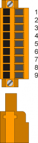
2.1.3 2 SSI absolute counters
| CN22 | Terminal | Symbol | Description | Address |
|---|---|---|---|---|
| | 1A | Internal bridge 1A-2A-1B-2B | ||
| 2A | ||||
| 3A | DATA1+ | DATA in SSI1 | 1 | |
| 4A | DATA1- | |||
| 5A | CLOCK1+ | CLOCK out SSI1 | ||
| 6A | CLOCK1- | |||
| 7A | 0V | Common for count inputs | ||
| 1B | Internal bridge 1A-2A-1B-2B | |||
| 2B | ||||
| 3B | DATA2+ | DATA in SSI2 | 2 | |
| 4B | DATA2- | |||
| 5B | CLOCK2+ | CLOCK out SSI1 | ||
| 6B | CLOCK2- | |||
| 7B | 0V | Common for count inputs | ||
2.2 Analog inputs
2.2.1 4 potentiometric, voltmetric and amperometric analog inputs 12bit
| The electrical features are given in paragraph Electrical features. The wiring examples are given in paragraph Connection examples |
|---|
| CN28 | Terminal | Symbol | Description | Address |
|---|---|---|---|---|
 | 1 | GAI | Common for analog inputs | |
| 2 | IA1 | analog input 1 | 3.AI01 | |
| 3 | SEL1V | Analog input selector 1 voltmetric 0-10V1) | ||
| 4 | SEL1C | Analog input selector 1 amperometric 0-20mA2) | ||
| 5 | GAI | Common for analog inputs | ||
| 6 | IA2 | analog input 2 | 3.AI02 | |
| 7 | SEL2V | Analog input selector 2 voltmetric 0-10V3) | ||
| 8 | SEL2C | Analog input selector 2 amperometric 0-20mA4) | ||
| 9 | VREF | Reference voltage |
| CN29 | Terminal | Symbol | Description | Address |
|---|---|---|---|---|
| | 3 | GAI | Common for analog inputs | |
| 2 | IA3 | analog input 3 | 3.AI03 | |
| 3 | SEL3V | Analog input selector 3 voltmetric 0-10V1) | ||
| 4 | SEL3C | Analog input selector 3 amperometric 0-20mA2) | ||
| 5 | GAI | Common for analog inputs | ||
| 6 | IA4 | analog input 4 | 3.AI04 | |
| 7 | SEL4V | Analog input selector 4 voltmetric 0-10V3) | ||
| 8 | SEL4C | Analog input selector 4 amperometric 0-20mA4) | ||
| 9 | VREF | Reference voltage |
2.3 Digital outputs
2.3.1 32 protected digital outputs
| The electric features are listed on the paragraph Electric features. The example of the connections are listed on the Connection examples |
|---|
| CN7 | Terminal | Simbol | Description | Address |
|---|---|---|---|---|
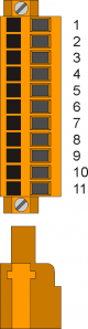 | 1 | V1+ | Input for outputs power supply O1÷O8 (12÷28V dc) | |
| 2 | O1 | Digital output 1 | 3.OUT01 | |
| 3 | O2 | Digital output 2 | 3.OUT02 | |
| 4 | V1- | Input for outputs power supply O1÷O8 (0V dc) | ||
| 5 | O3 | Digital output 3 | 3.OUT03 | |
| 6 | O4 | Digital output 4 | 3.OUT04 | |
| 7 | V1- | Input for outputs power supply O1÷O8 (0V dc) | ||
| 8 | O5 | Digital output 5 | 3.OUT05 | |
| 9 | O6 | Digital output 6 | 3.OUT06 | |
| 10 | O7 | Digital output 7 | 3.OUT07 | |
| 11 | O8 | Digital output 8 | 3.OUT08 |
| CN8 | Terminal | Simbol | Description | Address |
|---|---|---|---|---|
| | 1 | V2+ | Input for outputs power supply O9÷O16 (12÷28V dc) | |
| 2 | O9 | Digital output 9 | 3.OUT09 | |
| 3 | O10 | Digital output 10 | 3.OUT10 | |
| 4 | V2- | Input for outputs power supply (0V dc) | ||
| 5 | O11 | Digital output 11 | 3.OUT11 | |
| 6 | O12 | Digital output 12 | 3.OUT12 | |
| 7 | V2- | Input for outputs power supply O9÷O16 (0V dc) | ||
| 8 | O13 | Digital output 13 | 3.OUT13 | |
| 9 | O14 | Digital output 14 | 3.OUT14 | |
| 10 | O15 | Digital output 15 | 3.OUT15 | |
| 11 | O16 | Digital output 16 | 3.OUT16 |
| CN9 | Terminal | Simbol | Description | Address |
|---|---|---|---|---|
| | 1 | V3+ | Input for outputs power supply O17÷O24 (12÷28V dc) | |
| 2 | O17 | Digital output 17 | 3.OUT17 | |
| 3 | O18 | Digital output 18 | 3.OUT18 | |
| 4 | V3- | Input for outputs power supply O17÷O24 (0V dc) | ||
| 5 | O19 | Digital output 19 | 3.OUT19 | |
| 6 | O20 | Digital output 20 | 3.OUT20 | |
| 7 | V3- | Input for outputs power supply O17÷O24 (0V dc) | ||
| 8 | O21 | Digital output 21 | 3.OUT21 | |
| 9 | O22 | Digital output 22 | 3.OUT22 | |
| 10 | O23 | Digital output 23 | 3.OUT23 | |
| 11 | O24 | Digital output 24 | 3.OUT24 |
| CN10 | Terminal | Simbol | Description | Address |
|---|---|---|---|---|
| | 1 | V4+ | Input for outputs power supply O25÷O32 (12÷28V dc) | |
| 2 | O25 | Digital output 25 | 3.OUT25 | |
| 3 | O26 | Digital output 26 | 3.OUT26 | |
| 4 | V4- | Input for outputs power supply O25÷O32 (0V dc) | ||
| 5 | O27 | Digital output 27 | 3.OUT27 | |
| 6 | O28 | Digital output 28 | 3.OUT28 | |
| 7 | V4- | Input for outputs power supply O25÷O32 (0V dc) | ||
| 8 | O29 | Digital output 29 | 3.OUT29 | |
| 9 | O30 | Digital output 30 | 3.OUT30 | |
| 10 | O31 | Digital output 31 | 3.OUT31 | |
| 11 | O32 | Digital output 32 | 3.OUT32 |
2.3.2 5 uscite STEP-DIREZIONE
| Le caratteristiche elettriche sono riportate nel paragrafo Caratteristiche elettriche. Gli esempi di collegamento sono riportati nel paragrafo Esempi di collegamento |
|---|
| CN23 | Morsetto | Simbolo | Descrizione | Indirizzo | |
|---|---|---|---|---|---|
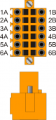 | 1A | VD1 | Internal bridge 1A -1B | ||
| 2A | DIR1+ | Uscita DIREZIONE 1 | Push-Pull Line Driver | 3.PULSE01 | |
| 3A | STEP1+ | Uscita STEP 1 | |||
| 4A | DIR2+ | Uscita DIREZIONE 2 | 3.PULSE02 | ||
| 5A | STEP2+ | Uscita STEP 2 | |||
| 6A | 0V | Comune delle uscite stepper | |||
| 1B | VD1 | Internal bridge 1A -1B | |||
| 2B | DIR1- | Uscita complementare DIREZIONE 1 | Uscite complementari per l'utilizzo nei drive con ingressi Line-Driver | ||
| 3B | STEP1- | Uscita complementare STEP 1 | |||
| 4B | DIR2- | Uscita complementare DIREZIONE 2 | |||
| 5B | STEP2- | Uscita complementare STEP 2 | |||
| 6B | 0V | Comune delle uscite stepper | |||
| CN24 | Morsetto | Simbolo | Descrizione | Indirizzo | |
|---|---|---|---|---|---|
| | 1A | VD2 | Internal bridge 1A -1B | ||
| 2A | DIR3+ | Uscita DIREZIONE 3 | Push-Pull Line Driver | 3.PULSE03 | |
| 3A | STEP3+ | Uscita STEP 3 | |||
| 4A | DIR4+ | Uscita DIREZIONE 4 | 3.PULSE04 | ||
| 5A | STEP4+ | Uscita STEP 4 | |||
| 6A | 0V | Comune delle uscite stepper | |||
| 1B | VD2 | Internal bridge 1A -1B | |||
| 2B | DIR3- | Uscita complementare DIREZIONE 3 | Uscite complementari per l'utilizzo nei drive con ingressi Line-Driver | ||
| 3B | STEP3- | Uscita complementare STEP 3 | |||
| 4B | DIR4- | Uscita complementare DIREZIONE 4 | |||
| 5B | STEP4- | Uscita complementare STEP 4 | |||
| 6B | 0V | Comune delle uscite stepper | |||
| CN25 | Morsetto | Simbolo | Descrizione | Indirizzo | |
|---|---|---|---|---|---|
| | 1A | VD3 | Internal bridge 1A -1B | ||
| 2A | DIR5+ | Uscita DIREZIONE 5 | Push-Pull Line Driver | 3.PULSE05 | |
| 3A | STEP5+ | Uscita STEP 5 | |||
| 4A | - | n.c. | |||
| 5A | - | n.c. | |||
| 6A | 0V | Comune delle uscite stepper | |||
| 1B | VD3 | Internal bridge 1A -1B | |||
| 2B | DIR5- | Uscita complementare DIREZIONE 5 | Uscite complementari per l'utilizzo nei drive con ingressi Line-Driver | ||
| 3B | STEP5- | Uscita complementare STEP 5 | |||
| 4B | - | n.c. | |||
| 5B | - | n.c. | |||
| 6B | 0V | Comune delle uscite stepper | |||
Inserendo uno dei vari ponticelli JP1-JP9, è possibile scegliere la Tensione di funzionamento nominale delle uscite STEP e DIR.
 | Deve essere inserito un solo ponticello alla volta per ogni connettore Se viene selezionata una delle due tensioni 5V(JP3,JP6,JP9) o 12V(JP1,JP4,JP7) i morsetti 1A e 1B devono rimanere scollegati |
|---|
.
| Nome jumper | Impostazione | Tensione nominale | |
|---|---|---|---|
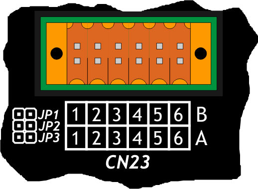 | JP1 | INSERITO | 12V (Tensione erogata dallo strumento) |
| JP2 | INSERITO | VD1 (Tensione che deve essere fornita ai morsetti 1A o 1B) | |
| JP3 | INSERITO | 5V (Tensione erogata dallo strumento) | |
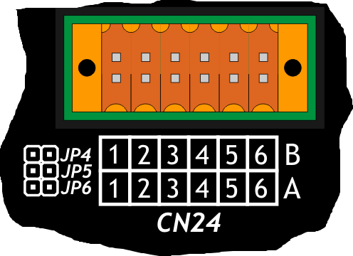 | JP4 | INSERITO | 12V (Tensione erogata dallo strumento) |
| JP5 | INSERITO | VD2 (Tensione che deve essere fornita ai morsetti 1A o 1B) | |
| JP6 | INSERITO | 5V (Tensione erogata dallo strumento) | |
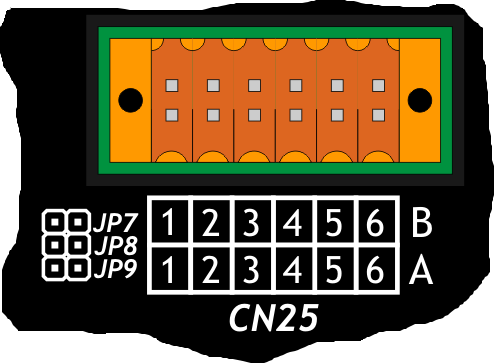 | JP7 | INSERITO | 12V (Tensione erogata dallo strumento) |
| JP8 | INSERITO | VD3 (Tensione che deve essere fornita ai morsetti 1A o 1B) | |
| JP9 | INSERITO | 5V (Tensione erogata dallo strumento) |
 | JP1,JP4,JP7 |
| JP2,JP5,JP8 | |
| JP3,JP6,JP9 |
2.4 Uscite analogiche
2.4.1 8 uscite analogiche +/-10V, 16bit
| Le caratteristiche elettriche sono riportate nel paragrafo Caratteristiche elettriche. Gli esempi di collegamento sono riportati nel paragrafo Esempi di collegamento |
|---|
| CN26 | Morsetto | Simbolo | Descrizione | Indirizzo |
|---|---|---|---|---|
 | 1 | GAO | Comune uscite analogiche | |
| 2 | AO1 | Uscita analogica 1 | 3.AN01 | |
| 3 | AO2 | Uscita analogica 2 | 3.AN02 | |
| 4 | GAO | Comune uscite analogiche | ||
| 5 | AO3 | Uscita analogica 3 | 3.AN03 | |
| 6 | AO4 | Uscita analogica 4 | 3.AN04 |
| CN27 | Morsetto | Simbolo | Descrizione | Indirizzo |
|---|---|---|---|---|
| | 1 | GAO | Comune uscite analogiche | |
| 2 | AO5 | Uscita analogica 5 | 3.AN05 | |
| 3 | AO6 | Uscita analogica 6 | 3.AN06 | |
| 4 | GAO | Comune uscite analogiche | ||
| 5 | AO7 | Uscita analogica 7 | 3.AN07 | |
| 6 | AO8 | Uscita analogica 8 | 3.AN08 |
3. Esempi di collegamento
3.1 Ingressi digitali

3.2 Ingressi di conteggio Line Driver

3.3 Ingressi di conteggio PNP / Push Pull

3.4 Conteggi assoluti SSI

3.5 Ingressi analogici voltmetrici e amperometrici

3.6 Ingressi analogici voltmetrici e potenziometrici

3.7 Uscite digitali protette

3.8 Uscite STEP - DIREZIONE 12V

3.9 Uscite STEP - DIREZIONE 24V

3.10 Uscite analogiche

4. Caratteristiche elettriche
Di seguito sono riportate le caratteristiche elettriche hardware.
I valori di frequenze massime e minime e tempi di acquisizione effettivi, possono comunque dipendere da eventuali filtri software aggiuntivi, vedere per esempio la variabile di sistema “QMOVE:sys004”.
4.0.1 Ingressi digitali standard
| Tipo | Sinking (PNP) |
| Tempo min. di acquisizione (hardware) | 3ms |
| Tensione di funzionamento nominale | 12÷24Vdc |
| Tensione stato logico 0 | 0÷2 V |
| Tensione stato logico 1 | 10,5 ÷ 26,5 V |
| Corrente assorbita | 2mA@10.5V / 8mA@26.5V |

4.0.2 Ingressi digitali veloci
| Tipo di polarizzazione | NPN / PNP |
| Frequenza massima | 200KHz |
| Tempo min. di acquisizione (hardware) | 5µs |
| Isolamento | 1000Vrms |
| Tensione di funzionamento nominale | 24Vdc |
| Tensione stato logico 0 | 0÷2 V |
| Tensione stato logico 1 | 10,5 ÷ 26,5 V |
| Caduta di tensione interna | 1,2 V |
| Resistenza di ingresso | 2700Ω |

4.0.3 Ingressi di conteggio bidirezionale a 200KHz
I valori riportati in tabella si riferiscono ai segnali d'ingresso A, B e Z.
Il valore di frequenza massima, riportato in tabella si riferisce a dei segnali delle fasi A e B con un DutyCycle = 50%
Con frequenze di conteggio superiori ai 50KHz è preferibile l'uso di encoder di tipo Line-Driver.
| Tipo di polarizzazione | PNP/PP |
| Frequenza massima | 200KHz |
| Tempo min. di acquisizione | 5µs |
| Isolamento | 1000Vrms |
| Tensione di funzionamento nominale | 24Vdc |
| Tensione stato logico 0 | 0 ÷ 2 V |
| Tensione stato logico 1 | 10,5 ÷ 26,5 V |
| Caduta di tensione interna | 1,2V |
| Resistenza di ingresso | 3000Ω |
Line-Driver
| Tipo di polarizzazione | Line-Driver |
| Frequenza massima | 200KHz |
| Tempo min. di acquisizione | 5µs |
| Isolamento | 1000Vrms |
| Tensione di funzionamento nominale (PHx+ ⇔ PHx-) | 5Vdc |
| Tensione stato logico 0 (PHx+ ⇔ PHx-) | 0÷1,5 V |
| Tensione stato logico 1 (PHx+ ⇔ PHx-) | 2÷5 V |
| Caduta di tensione interna | 1,2V |
| Resistenza di ingresso | 150Ω |

4.0.4 Contatori assoluti SSI
| Frequenza | 320KHz |
| Modo di funzionamento | Differenziale |
| Impedenza d'ingresso | >= 12KΩ |
| Limite corrente cortocircuito | >= 35mA |

4.0.5 Ingressi analogici potenziometrici
| Tipo di collegamento | Potenziometrico 1KΩ÷20KΩ |
| Risoluzione | 12bit/16bit |
| Tensione di riferimento erogata | 2,5Vdc |
| Corrente massima erogata dal riferimento | 10mA |
| Resistenza d'ingresso | 10MΩ |
| Max. errore di linearità | + 0,1% Vfs |
| Max. errore di offset | + 0,1% Vfs |
| S.n. | 71 dB |
| Velocità di aggiornamento | 1ms |
| Isolamento | 1000 Vrms |

4.0.6 Ingressi analogici voltmetrici
| Tipo di collegamento | Voltmetrico 0÷10V |
| Risoluzione | 12bit/16bit |
| Resistenza d'ingresso (Rin) | 20KΩ |
| Valore di danneggiamento | 20V |
| Max. errore di linearità | + 0,1% Vfs |
| Max. errore di offset | + 0,1% Vfs |
| S.n. | 71 dB |
| Velocità di aggiornamento | 1ms |
| Isolamento | 1000 Vrms |

4.0.7 Ingressi analogici amperometrici
| Tipo di collegamento | Amperometrico (0-20 mA) |
| Risoluzione | 12bit/16bit |
| Resistenza d'ingresso | 125Ω |
| Valore di danneggiamento | 25 mA |
| Max. errore di linearità | + 0,1% Vfs |
| Max. errore di offset | + 0,1% Vfs |
| S.n. | 71 dB |
| Velocità di aggiornamento | 1ms |
| Isolamento | 1000 Vrms |

4.0.8 Uscite digitali protette
| Carico commutabile | Dc (PNP) |
| Max. tensione di funzionamento | 28V |
| Isolamento | 1000Vpp |
| Caduta di tensione interna max. | 600mV |
| Resistenza interna massima @ON | 90mΩ |
| Corrente max. di protezione | 12A |
| Corrente max. di funzionamento | 2A |
| Corrente max. @OFF | 5µA |
| Tempo di massimo commutazione da ON a OFF | 270µs |
| Tempo di massimo commutazione da OFF a ON | 250µs |

4.0.9 Uscite per motore stepper
| Tipo di polarizzazione | Push-Pull / Line-Driver |
| Massima frequenza d'uscita | 300KHz |
| Isolamento | 1000Vpp |
| Corrente max. di funzionamento | 20mA |
| Tensione nominale | 12Vdc1) |

4.0.10 Uscite analogiche
| Tipo di collegamento | In modo comune |
| Isolamento | 1000Vrms |
| Range di tensione (minimo a vuoto) | -9,8V ÷ +9,8V |
| Max. variazione offset in funzione della temperatura | +/- 5mV |
| Risoluzione | 16bit |
| Corrente massima | 1mA |
| Variazione dell'uscita in funzione del carico | 100 µV/mA |
| Resistenza d'uscita | 249Ω |
