THE COUNTER3 DEVICE
1. Introduction
The COUNTER3 device is used to acquire information from a two-way counter. Its main characteristics:
-
conversion of pulses to selected unit measures
-
position updating with recovery of unit measure fractions
-
position capturing on activation of an interrupt digital input
-
comparison between measured position and an activation threshold of digital outputs.
1.1 Declaring the device
To use the device it has to be declared in the INTDEVICE section of the configuration unit.
INTDEVICE
<device name> COUNTER3 <TCamp> <ICont> <IdxA> <Out1> <Out2>
Where:
| Field name | Description | Example | Notes |
|---|---|---|---|
| <device name> | Name assigned to the device. | Count | - |
| COUNTER3 | Keyword identifying the two-way count device | - | - |
| <TCamp> | Device sampling time (1-255 ms) | 4 | - |
| <ICont> | Counter address in card | 3.CNT01 | Enter X.X to ignore |
| <IdxA> | Hardware interrupt line number to capture the count | 1 | Enter X to ignore |
| <Out1> | Comparator output 1 address | 3.OUT01 | Enter X.X to ignore |
| <Out2> | Comparator output 2 address | 3.OUT02 | Enter X.X to ignore |
Example:
INTDEVICE
Count  COUNTER3  2  2.CNT02  3    2.OUT01  2.OUT02
 | All fields in the declaration are mandatory and must be on the same line. Set X.X or X if a resource is not available or not used. If a resource is disabled all the functionalities related to the device are disabled. |
|---|
1.2 Execution Description
A block chart of the device:
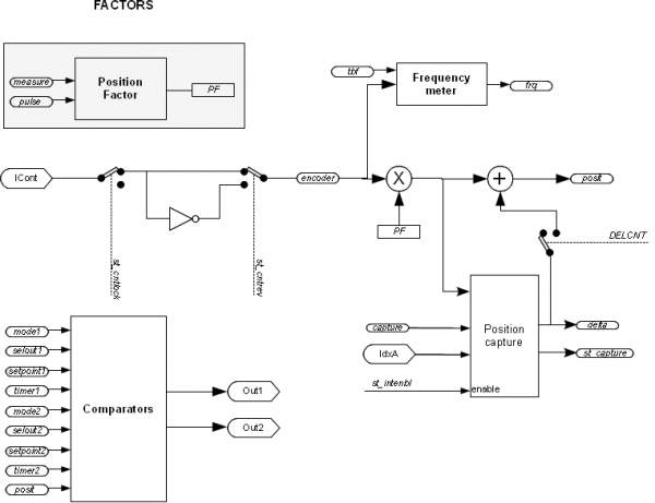
1.2.0.1 Factors
The “Factors” block calculates the conversion factors for position and speed. The “position factor” (PF) is a position conversion coefficient expressed in the unit measure of the of the transducer in the position unit measure (Um), and vice versa. Usually the position unit measure is, for example, metres or millimetres or centimetres, while the transducer unit measure, as an encoder, is always pulses. The parameters used to calculate the position factor are pulse and measure and it is calculated as a ratio between the two.
1.2.0.2 Acquisition of the actual position on an interrupt digital input
The INTENBL and INTDSBL commands enable (st_intenbl=1) and disable (st_intenbl=0) the interrupt line connected to the zero pulse of the transducer or another sensor. The value of the capture parameter defines which pulse front the instant count is frozen and the count captured is introduced in the delta parameter. The st_capture status signals that the capture is made.
1.2.0.3 Comparators
The device also provides two comparators that can be used to compare the actual value of the posit parameter with two values (setpoint1 and setpoint2) set by the programming. As a result the comparators act on two digital outputs, activating or disactivating them when the set thresholds are met according to various conditions. There are two outputs available (as seen in the the device declaration and block chart) and there is a good level of personalisation: each comparator can select which output to command and based on which conditions. The mode1 parameters (controlling comparator 1) selects the activation or disattivazione policy of the corresponding output according to given rules.
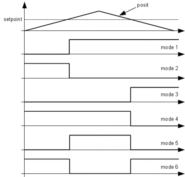
The figure shows examples of the different execution modes:
-
mode 0: the output stays in its status
-
mode 1: the output is activated when the position in pulse fronts is greater than the setpoint;
-
mode 2: the output is disactivated when the position in pulse fronts is greater than the setpoint;
-
mode 3: the output is activated when the position in pulse fronts is less than the setpoint;
-
mode 4: the output is disactivated when the position in pulse fronts is less than the setpoint;
-
mode 5: the output is activated when the position in pulse fronts is greater than the setpoint and is disactivated when the position in pulse fronts is less than the setpoint;
-
mode 6: the output is disactivated when the position in pulse fronts is greater than the setpoint and is activated when the position in pulse fronts is less than the setpoint.
1.2.0.4 Delta Actual position
The device always gives the absolute position of the axis. The count change can also be performed by directly writing the new value of the
posit parameter.
If 100 unit measures are subtracted from the count:
Count.posit = Count.posit - 100
An error is introduced because it sets the position posit = -100, when the axis may have an intermediary position between one unit measure and the next (e.g. 100.3). This fraction (0.3) is lost and if repeated can cause a build up of a significant error.
For this reason there is the DELCNT command that can change the posit by a value set by the delta parameter.
For instance, if pulse and measure are configured to express the position in tenths of a degree and posit expresses the angular position. For this to always fall between zero and 360 degrees, the following code must be added:
  IF Count.posit GE 3600
    Count.delcnt = -3600
    Count.DELCNT
  ENDIF
For the command execution conditions see its specific description.
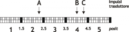
Execution of the DELCNT command is ensured even if a unit measure cannot be expressed as a finite number of pulse fronts. For instance with parameters measure = 1000 and pulse = 1024, the value 3600 of the previous example corresponds to 3686.4 pulses. A complex internal algorhythm allows the device to consider the decimal part of this value and by internal accumulators, it becomes part of the information used to change the posit value.
Example:
If pulse = 10, measure = 1, the axis position reading is 2 and it is found at point A.
To add two unit measures to the posit position. The instructions :
Count.posit = Count.posit + 2
take the axis to the new position B. The instructions:
  Count.delta = 2
  Count.DELCNT Asse
take the axis to position C.
If posit is modified directly without using the DELCNT command (as in the first example) an error is introduced.
 | To send a sequence of DELCNT commands, it is best to calculate the size of the addition and only send the command once. If this is not possible great care must be taken to avoid sending a sequence of commands not separated by a read instruction on the device parameter. Example: Count.delta = 3 Count.DELCNT WAIT Count.delta Count.delta = 40 Count.DELCNT |
|---|
1.3 Errors management
The presence of an error in device is reported in the state st_error.
When st_error is equal to 1, we find in the variable errcode the type of error intervened (see table) and in the variable errvalue an indication of the cause of the error.
If the device is in error, to resume production you need to erase the state through the command RSERR
1.4 Warnings management
The presence of a warning in device is reported in the state st_warning.
When st_warning is equal to 1, we find in the variable wrncode the type of warning intervened (see table) and in the variable wrnvalue an indication of the cause of the warning.
| Code | Priority | Description |
|---|---|---|
| 1 | 0 | Command not executed |
To clear the status st_warning we must send the command RSWRN.
1.5 List of Parameters
measure
| Short description | Reference measurement for the calculation of the conversion factor between pulse fronts and unit measures |
|---|---|
| Dimension | Long |
| Default value | Retentive |
| Access type | Read - Write |
| Unit measure | Um |
| Valid range | 1-999999 |
| Parameter ID | - |
| Write conditions | - |
Description:
Indication of the distance, in unit measures, travelled by the axis to obtain the pulse fronts set in the pulse parameter. This parameter is used to calculate the conversion factor between pulse fronts and unit measures.
posit = encoder * measure / pulse
The measure / pulse ratio must be between 0.00935 and 1.
pulse
| Short description | Number of pulse fronts for the calculation of the conversion facter between pulse fronts and unit measures |
|---|---|
| Dimension | Long |
| Default value | Retentive |
| Access type | Read - Write |
| Unit measure | - |
| Valid range | 1-999999 |
| Parameter ID | - |
| Write conditions | - |
Description:
Indication of the number of pulse fronts that the two-way transducer will generate to obtain a movement equal to measure. This parameter is used to calculate the conversion factor between pulse fronts and unit measures.
posit = encoder * measure / pulse
The measure / pulse ratio must be between 0.00935 and 1.
posit
| Short description | Actual position in unit measures |
|---|---|
| Dimension | Long |
| Default value | Retentive |
| Access type | Read - Write |
| Unit measure | Um |
| Valid range | - |
| Parameter ID | - |
| Write conditions | - |
Description:
The actual position value of the axis in unit measures.
posit = encoder * measure / pulse.
encoder
| Short description | Actual position in pulse fronts |
|---|---|
| Dimension | Long |
| Default value | Retentive |
| Access type | Read - Write |
| Unit measure | Pulse fronts |
| Valid range | - |
| Parameter ID | - |
| Write conditions | - |
Description:
The actual position expressed in pulse fronts.
delta
| Short description | Variation of instant position for using the DELCNT command |
|---|---|
| Dimension | Long |
| Default value | Retentive |
| Access type | Read - Write |
| Unit measure | Um |
| Valid range | -999999-999999 |
| Parameter ID | - |
| Write conditions | - |
Description:
The value added to the instant position when a DELCNT command is sent. Moreover the position in the delta parameter is memorised when using the acquisition on activation of an interrupt digital input.
axetype
| Short description | Type of axis |
|---|---|
| Dimension | Flag |
| Default value | Retentive |
| Access type | Read - Write |
| Unit measure | - |
| Valid range | -999999-999999 |
| Parameter ID | - |
| Write conditions | - |
Description:
Selection of the type of axis being commanded:
-
0: linear axis
-
1: circular axis (angular). The count starts again from zero after reading the measure value.
capture
| Short description | Position capture mode on activation of an interrupt digital input |
|---|---|
| Dimension | Byte |
| Default value | Retentive |
| Access type | Read - Write |
| Unit measure | - |
| Valid range | 0-2 |
| Parameter ID | - |
| Write conditions | - |
Description:
The parameter defines the capture mode for the position in pulse fronts on activation of an interrupt digital input:
-
0: disabled,
-
1: One-shot on down front. The instant position is captured in pulse fronts on the first down front of the interrup digital input signal after activation of st_intenbl;
-
2: One-shot on up front . The instant position is captured in pulse fronts on the first up front of the interrupt digital input signal after activation of st_intenbl.
tbf
| Short description | Frequency meter sampling time |
|---|---|
| Dimension | Byte |
| Default value | Retentive |
| Access type | Read - Write |
| Unit measure | - |
| Valid range | 0-5 |
| Parameter ID | - |
| Write conditions | - |
Description:
Definition of the frequency meter sampling time:
-
0: 240 ms,
-
1: 480 ms,
-
2: 24 ms,
-
3: 120 ms,
-
4: 960 ms,
-
5: 1200 ms.
The device, for calculation of the signal frequency input at the two-way counter (frq parameter), counts the number of pulses received in a time period defined by the tbf parameter and calculates an average value. The lower the sampling time, the faster the update of the frq parameter, however take care at low frequencies because the sampling time may not be long enough to sample.
frq
| Short description | Input signal frequency |
|---|---|
| Dimension | Long |
| Default value | 0 |
| Access type | Read |
| Unit measure | Hz |
| Valid range | - |
| Parameter ID | - |
| Write conditions | - |
Description:
It's the value of the two-way count input signal frequency. The updates rate is dependent on the sampling time selected by the tbf parameter.
mode1
| Short description | Output command mode indicated in selout1 by the comparator |
|---|---|
| Dimension | Byte |
| Default value | Retentive |
| Access type | Read - Write |
| Unit measure | - |
| Valid range | 0-6 |
| Parameter ID | - |
| Write conditions | - |
Description:
This parameter defines the activation and disattivazione rules for the output indicated in the selout1 parameter by the comparator.
selout1
| Short description | Output commanded by comparator 1 |
|---|---|
| Dimension | Byte |
| Default value | Retentive |
| Access type | Read - Write |
| Unit measure | - |
| Valid range | 0-1 |
| Parameter ID | - |
| Write conditions | - |
Description:
Indication of the output is commanded by comparator 1:
-
0: Out1,
-
1: Out2.
setpoint1
| Short description | Comparation threshold for comparator 1 |
|---|---|
| Dimension | Long |
| Default value | Retentive |
| Access type | Read - Write |
| Unit measure | Um |
| Valid range | -999999-999999 |
| Parameter ID | - |
| Write conditions | - |
Description:
Definition of the threshold setpoint for comparing with the instant position value in pulse fronts. The modified output is indicated by the selout1 parameter.
timer1
| Short description | Activation delay time of selout1 output |
|---|---|
| Dimension | Word |
| Default value | Retentive |
| Access type | Read - Write |
| Unit measure | ms |
| Valid range | -999999-999999 |
| Parameter ID | - |
| Write conditions | - |
Description:
Definition for the output indicated in selout1, of a time period between the event commanding the actual switching (i.e. a delay on the digital output activation or disactivation is introduced.)
mode2
| Short description | Output command mode indicated in selout1 by the comparator |
|---|---|
| Dimension | Byte |
| Default value | Retentive |
| Access type | Read - Write |
| Unit measure | - |
| Valid range | 0-6 |
| Parameter ID | - |
| Write conditions | - |
Description:
This parameter defines the activation and disactivation rules for the output indicated in the selout2 parameter by the comparator.
selout2
| Short description | Output commanded by comparator 1 |
|---|---|
| Dimension | Byte |
| Default value | Retentive |
| Access type | Read - Write |
| Unit measure | - |
| Valid range | 0-1 |
| Parameter ID | - |
| Write conditions | - |
Description:
Indication of which output is commanded by comparator 2:
-
0: Out1,
-
1: Out2.
setpoint2
| Short description | Comparation threshold for comparator 1 |
|---|---|
| Dimension | Long |
| Default value | Retentive |
| Access type | Read - Write |
| Unit measure | Um |
| Valid range | -999999-999999 |
| Parameter ID | - |
| Write conditions | - |
Description:
Definition of the setpoint (i.e. threshold) where the instant position is compared in pulse fronts. The output consequently modified is indicated by the selout2 parameter.
timer2
| Short description | Activation delay time for selout1 output |
|---|---|
| Dimension | Word |
| Default value | Retentive |
| Access type | Read - Write |
| Unit measure | ms |
| Valid range | -999999-999999 |
| Parameter ID | - |
| Write conditions | - |
Description:
The output indicated by selout2, this parameter defines a delay time between the event that commands the output switching and the actual switching (i.e. a delay on the digital output activation or disactivation)
errcode
| Short description | error ID code |
|---|---|
| Dimension | Byte |
| Default value | 0 |
| Access type | Read |
| Unit measure | - |
| Valid range | 0-100 |
| Parameter ID | - |
| Write conditions | - |
Description:
Indication of the type of error tripped in the system. When st_error = 1 is found in the errcode variable, the type of error and the errvalue variable gives an indication on the cause of error. If an error trips in the device, to restore operation bisogna cancellare the st_error status must be eliminated by the RSERR command.
This device does not create an error code.)
errvalue
| Short description | Cause of error ID code |
|---|---|
| Dimension | Byte |
| Default value | 0 |
| Access type | Read |
| Unit measure | - |
| Valid range | 0-100 |
| Parameter ID | - |
| Write conditions | - |
Description:
Indication of the cause of an error tripped in the system. The code is only valid if st_error = 1)
wrncode
| Short description | Warning ID code |
|---|---|
| Dimension | Byte |
| Default value | 0 |
| Access type | Read |
| Unit measure | - |
| Valid range | 0-100 |
| Parameter ID | - |
| Write conditions | - |
Description:
Indication of the type of warning tripped in the system. The st_warning status indicates a non-critical event that nevertheless assures device execution. When st_warning is 1, the wrncode variable will contain the type of warning (see table) and the wrnvalue variable will contain the cause of the warning. The st_warning status is reset by sending the RSWRN command.)
| Code | Priority | Description |
|---|---|---|
| 1 | 0 | Command not executed |
—-
wrnvalue
| Short description | Cause of warning ID code |
|---|---|
| Dimension | Byte |
| Default value | 0 |
| Access type | Read |
| Unit measure | - |
| Valid range | 0-100 |
| Parameter ID | - |
| Write conditions | - |
Description:
Indication of the cause of warning tripped in the system.)
1.6 Status List
st_cntlock
| Short description | Update position status disabled |
|---|---|
| Default value | Retentive |
| Status ID | - |
Description
Signal that the position update is blocked :
-
0: position update enabled
-
1: position update disabled
st_cntrev
| Short description | Invert position update status |
|---|---|
| Default value | Retentive |
| Status ID | - |
Description
Signal that the position update is inverted:
-
0: position update not inverted,
-
1: position update inverted
st_intenbl
| Short description | Interrupt digital input activation status |
|---|---|
| Default value | 0 |
| Status ID | - |
Description
Signal that the capture instant position is enabled on the interrupt digital input, which is activated by the INTENBL command and disactivated by the INTDSBL command or on the st_capture rising front.
st_capture
| Short description | Capture instant position activation |
|---|---|
| Default value | 0 |
| Status ID | - |
Description
The instant position capturing is activated, which is reset by the RSCAPTURE command.
st_int
| Short description | Interrupt digital input status |
|---|---|
| Default value | 0 |
| Status ID | - |
Description
Indication of the interrupt digital input status :
-
0: interrupt digital input disattivated
-
1: interrupt digital input activated
st_cmp1
| Short description | Comparator 1 status |
|---|---|
| Default value | 0 |
| Status ID | - |
Description
Activation signal for comparator 1:
-
0: comparator 1 disactivated
-
1: comparator 1 activated
st_cmp2
| Short description | Comparator 2 status |
|---|---|
| Default value | 0 |
| Status ID | - |
Description
Activation signal for comparator 2:
-
0: comparator 2 disactivated
-
1: comparator 2 activated
st_error
| Short description | Error present |
|---|---|
| Default value | 0 |
| Status ID | - |
Description
Indication of a device error status, to know the type of error refer to the errcode and errvalue variables:
-
0: error not present
-
1: error present
st_warning
| Short description | Warning present |
|---|---|
| Default value | 0 |
| Status ID | - |
Description
Indication of a warning status of the device, to know the type of warning refer to the wrncode and wrnalue variables:
-
0: warning not present
-
1: warning present
1.7 List of Commands
The commands provided to manage the device are listed below, ordered in decreasing priority. There are two ways to execute a command: * By the Qview watches panels * By a QCL instruction
In the second case the QCL program execution is blocked until the end of the command, which lasts between 0 and 2 sampling times.
CNTLOCK
| Short description | Disables update of the actual position |
|---|---|
| Condition | - |
| Default value | |
| Command ID | - |
Description
Disables update of the actual position. In this condition any axis movement is not detected
CNTUNLOCK
| Short description | Enables update of the actual position |
|---|---|
| Condition | - |
| Default value | |
| Command ID | - |
Description
Enables update of the actual position
CNTREV
| Short description | Inversion of position update |
|---|---|
| Condition | - |
| Default value | |
| Command ID | - |
Description
It can invert the sign of the position update; the st_cntrev status is set to 1.
CNTDIR
| Short description | Position update not inverted |
|---|---|
| Condition | - |
| Default value | |
| Command ID | - |
Description
Disables an inversion of the position update; the st_cntrev status is set to zero.
INTENBL
| Short description | Enables the actual position capture on activation of the interrupt digital input |
|---|---|
| Condition | capture>0 |
| Default value | |
| Command ID | - |
Description
Activates the actual position capture on activation of the interrupt digital input dedicata, the value is memorised in the delta parameter. The st_intenbl status is active
INTDSBL
| Short description | Disables the instant position capture on activation of the interrupt digital input |
|---|---|
| Condition | - |
| Default value | |
| Command ID | - |
Description
Disactivates the instant position capture on activation of the dedicated interrupt digital input. The st_intenbl status is disattivated
RSCAPTURE
| Short description | Deactivation of the capture status |
|---|---|
| Condition | - |
| Default value | |
| Command ID | - |
Description
Deactivates the st_capture capture status
DELCNT
| Short description | Modify posit command by a value equal to delta |
|---|---|
| Condition | st_intenbl=0 |
| Default value | |
| Command ID | - |
Description
The axis position is modified by agebraic addition of the value specified in the delta variable
SETCMP1
| Short description | Activate comparation 1 |
|---|---|
| Condition | - |
| Default value | |
| Command ID | - |
Description
Forced activation of the st_cmp1 status
RESCMP1
| Short description | Reset comparation 1 |
|---|---|
| Condition | - |
| Default value | |
| Command ID | - |
Description
Zero set st_cmp1 status
SETCMP2
| Short description | Activate comparation 2 |
|---|---|
| Condition | - |
| Default value | |
| Command ID | - |
Description
Forzed activation of the st_cmp2 status
RESCMP2
| Short description | Reset comparation 2 |
|---|---|
| Condition | - |
| Default value | |
| Command ID | - |
Description
Zero-set the st_cmp2 status
RSERR
| Short description | Reset error status |
|---|---|
| Condition | - |
| Default value | |
| Command ID | - |
Description
Zero-set the st_error status
RSWRN
| Short description | Reset warning status |
|---|---|
| Condition | - |
| Default value | |
| Command ID | - |
Description
Zero-set the st_warning status
1.8 Limitations
If you change the parameters measure or pulse after sending the command DELCNT, the remains of the conversion of the delta space in pulses are reset.
1.9 Application example
| This example can be compiled with QView 6.0 or higher. |
|---|
1.9.1 Configuration unit
;*************************************************************************************
; COUNTER3 example
;*************************************************************************************

; Bus declaration
BUS
  1  1K31F    20
  2  .        .
  3  1MG8F    .
  4  .

; Input declaration
INPUT
  ifEnableZ     F     3.INP01        ;Zero pulse capture enabling
  ifEnableComp  F     3.INP03        ;Comparation enabling

; Output declaration
OUTPUT
  out201      F     3.OUT01        ;Comparation output #1
  out202      F     3.OUT02        ;Comparation output #2

; Device declaration
INTDEVICE
Count    COUNTER3   2       3.CNT01     1       3.OUT01  3.OUT02

END
1.9.2 COUNTER3 management unit
SYSTEM
  slPrsPos   L  IN               ;Quota di preset
  slSet1     L  IN               ;Setpoint 1
  slSet2     L  IN               ;Setpoint 2

GLOBAL
  gfApp01    F
  gfApp02    F

BEGIN
;-------------------------------------------------------------------------------------
; Initialization
;-------------------------------------------------------------------------------------
Count.measure = 1000             ;measure per round
Count.pulse = 1000               ;pulse per round

Count.capture = 1                ;set capture on rise edge
IF slSet1 EQ 0
  slSet1 = 500                   ;Default value
ENDIF
IF slSet2 EQ 0
  slSet2 = 100                   ;Default value
ENDIF

MAIN:


  IF ifEnableZ                                 ;If the input is ON
    Count.INTENBL                              ;Zero pulse enabling
  ELSE
    Count.INTDSBL                              ;Zero pulse disabling
  ENDIF

  IF Count.st_capture                          ;When the count has captured
    Count.delta = -(Count.delta - slPrsPos)    ;load delta
    Count.DELCNT                               ;Set the new position
    Count.RSCAPTURE                            ;Reset the capture
  ENDIF

  IF ifEnableComp                              ;When it is enabled
    IF NOT gfApp01
      Count.mode1 = 5                           ;Set Mode1 for comparation 1
      Count.selout1 = 0
      Count.setpoint1 = slSet1
      Count.timer1 = 0
      Count.mode2 = 6                           ;Set Mode2 for comparation 2
      Count.selout2 = 1
      Count.setpoint2 = slSet2
      Count.timer2 = 0
      gfApp01 = 1
      gfApp02 = 0
    ENDIF
  ELSE                                         ;When it is not enabled
    IF NOT gfApp02
      Count.mode1 = 0                           ;Comparation 1 disabled
      RESOUT out201                            ;Reset output
      Count.selout1 = 0
      Count.mode2 = 0                           ;Comparation 1 disabled
      RESOUT out202                            ;Reset output
      Count.selout2 = 1
      gfApp01 = 0
      gfApp02 = 1
    ENDIF
  ENDIF

  WAIT 1
  JUMP MAIN

END