This is an old revision of the document!
A1-HMI-QC070


1. Informations
1.1 Release
| Document release | Description | Note | Date |
|---|---|---|---|
| 01 | New manual | Valid for hardware release from 02 and major release firmware from 5 | 10/12/2012 |
The controller has been designed for industral environments in conformity to EC directive 2004/108/CE.
-
EN 61000-6-4: Electromagnetic compatibility - Generic standard on emission for industrial environments
-
EN55011 Class A: Limits and measurement methods
-
EN 61000-6-2: Electromagnetic compatibility - Generic standard on immunity for industrial environments
-
EN 61000-4-2: Electromagnetic compatibility - Electrostatic discharge immunity
-
EN 61000-4-3: Immunity to radiated, radio-frequency electromagnetic field
-
EN 61000-4-4: Electrical fast transients
-
EN 61000-4-5: Surge immunity
-
EN 61000-4-6: Conducted disturbance induced by radio-frequency
-
Moreover the product is conform to the following standards:
-
EN 60529: Housing protection rating IP64
-
EN 60068-2-1: Environmental testing: Cold
-
EN 60068-2-2: Environmental testing: Dry heat
-
EN 60068-2-14: Environmental testing: Change of temperature
-
EN 60068-2-30: Environmental testing: Cyclic damp heat
-
EN 60068-2-6: Environmental testing: Sinusoidal vibration
-
EN 60068-2-27: Environmental testing: Shock vibration
-
EN 60068-2-64: Environmental testing: Random vibration
-
2. Description
A1-HMI-QC070 is a operator panel of the Qpanel+ series, can be equipped with:
Standard equipment 
Graphics LCD display 7” TFT-256 COLORS-800x480px 
Resistive Touch Screen Panel 
1 PROG PORT serial program port (Use with IQ009) accessory 
1 multistandard (RS232/422/485) serial - USER PORT 
1 Memory Card MMC/SD reader 
4 signal leds 8 system leds 
Anti-vibrating spring clamps 
Clock calendar 
Interchangeable front label 
Customizable function keys Optional equipment (See the table Hardware versions) 
16 standard digital inputs 
2 analog inputs 
8 digital outputs 2.1 Ordering code

The Ordering Code provides the exact product features. Model Features A1-HMI-QC070 - 01 / TP01 / G16 / 24 24 = Power supply G16 = Specialization cards TP00 = Keyboard code (TP00 = resisitive touch-screen panel, logo and customizable function keys);
TP01 = resisitive touch-screen panel, logo and QEM function keys01 = Firmware version (00 = not installed) A1 = HMI family
HMI = Human Machine Interface
Q = Qpanel series
C = Panel Graphic colors
070 = Graphics LCD display 7” TFT-256 COLORS-800x480px; front panel dimensions (216x168mm); keyboard with 7 keys + 11 leds; box with standard DIN 437002.2 Product Label
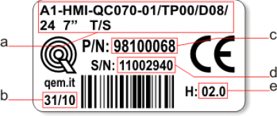
-
a - Ordering Code
-
b - Week made: indicates the week and year of manufacture
-
c - Part number: unique code that identifies an ordering code
-
d - Serial number: product serial number, different for individual product
-
e - Hardware release: version of hardware release
2.2.1 Hardware Versions
Is available the following versions:
Features Model Digital inputs Bidirectional counters
20KHz AB (24V-PP)Analog inputs 12bit Protected digital outputs A1-HMI-QC070-01/TP00/24V - - - - A1-HMI-QC070-01/TP00/D08/24V 8 - - 8 A1-HMI-QC070-01/TP00/G16/24V 16 - 2 8 A1-HMI-QC070-01/TP00/CG2/24V 12 2 2 8 2.3 Product Configuration
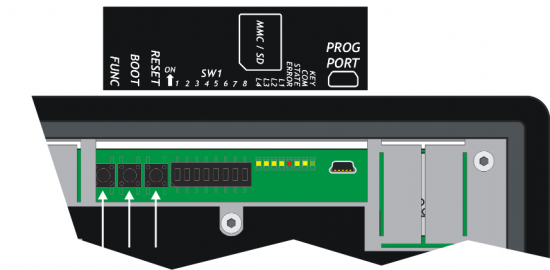
2.3.1 Front Panel
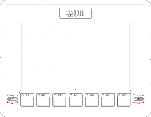
-
a = System led's
-
b = Function keys and led's
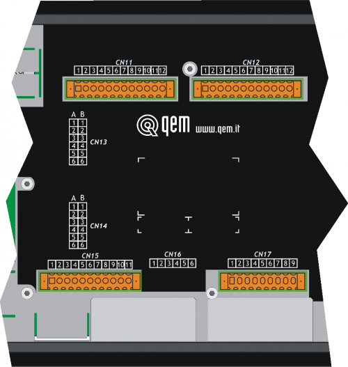
2.3.2 Back terminal blocks
The A1-HMI-QC070 has the specialization card.
3. Technical features
3.1 General features
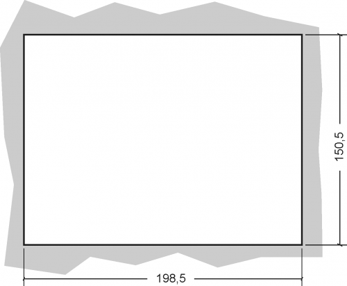
Weight (full hardware) 1Kg Housing Sheet metal Front panel Alluminium Outer Frame Self-extinguishing Noryl Display LCD TFT 7” TFT-256 COLORS-800 x 480px Touch screen wire Resistive Display dimensions 152,4(W) x 91,4(H)mm / 7” User led's 7 System led's 4 to front panel, 8 on rear Function keys 7 System keys 3 Operating temperature 0 ÷ 50°C Relative humidity 90% condensate free Altitude 0 - 2000m s.l.m. Transport and storage temperature -25 ÷ +70 °C Front protection rating IP64 3.2 Dimensions

Lengths in mm. 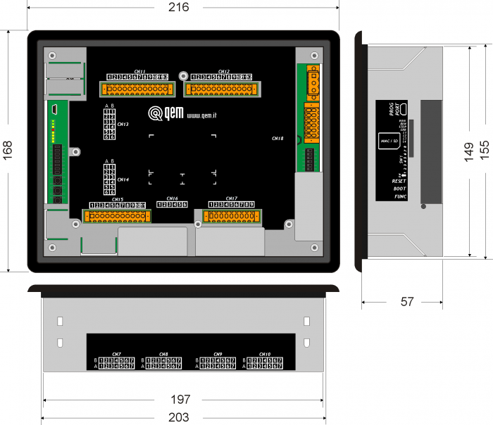
3.3 Hole template
Fit the controller in the hole.

Apply the brackets.
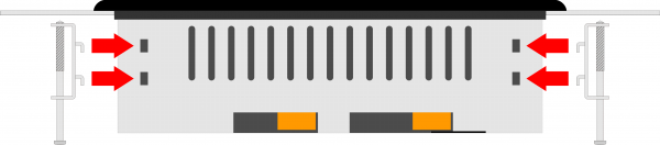

Before fixing the controller, check it is mounted firmly in the hole and the gasket under the frame makes a good seal. No liquids must enter and the frame must not deform. Screw the controller in place.
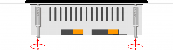
Warning: after putting the pin of fixing, do only half rotation to not tear the frame! • Please read carefully.
• See technical notes on Weidmuller terminals BLZF, BLZ and B2L.Types of Connectors
Family Wire Section
no end capsWire section
with end capsCharacteristics
of contactTools 
BLZF 3.5 0.3-1.50 mm2 0.3-1 mm2 
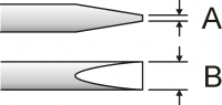
Open the self-locking, spring clip terminals with a flat blade screwdriver to DIN 5264-A as shown below
See the table below for recommended cap ends
To crimp the cap ends to the wire use the tool below
B2L 3.5 0.3-1.00 mm2 0,3-0.5 mm2 
BLZF 5.08 0.3-2.50 mm2 0.3-2.00 mm2 
BLZ 5.00 0.2-2.50 mm2 0.1-1 mm2 
The screw terminals can be tightened with a flat blade screwdriver to DIN 5264 as shown in fig.4.7
Tightening torque: 0.4 - 0.5 Nm.For a safer cabling, always use wire end caps
Tools
End caps
Wire section End cap section Make Model 0.1-0.3 mm2 0.95 mm2 Cembre PKE 308 0.3-0.5 mm2 1.32 mm2 Cembre PKE 508 BM BM00601 1 mm2 2.5mm2 BM00603 PK 108 BM BM00603 End cap crimping tool
 Use a crimp tool type “Cembre ND#4
cod. 2590086”
Use a crimp tool type “Cembre ND#4
cod. 2590086”
Screwdrivers
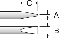 Screwdriver for opening self-locking spring clip terminals:
A = 0.6mm
B = 2.5mm max
C = 7 mm min
 Screwdriver for tightening screw terminals:
A = 0.6mm
B = 3.5mm
Procedure
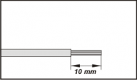
Strip 10mm of copper wire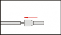
Fit the end cap and crimp it with a crimping tool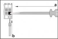
a) fit the screwdriver without turning it
b) fit the cable in the terminal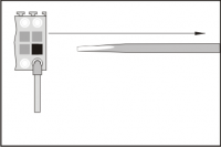
Remove the screwdriver4. Electrical features and connections

4.1 Power supply

The cabling must be carried out by specialist personnel and fitted with suitable anti-static precautions.
Before handling the controller, disconnect the power and all parts connected to it.
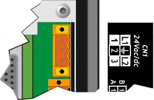
To guarantee compliance with EC regulations, the power supply must have a galvanic isolation of at least 1500Vac.Power supply 24 Vdc Voltage range 22 - 27 Vdc Max. absorption 30W CN1 Terminal Symbol Description 

1 L1/+ DC power positive 2 GROUND Gnd-PE (signals) 3 L2/- DC power 0V Connection examples for 24Vdc power supply
Use an isolated power unit with 24Vdc +/-5% output conform to EN60950-1. 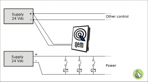
Use two separate power units: one for the control circuit and one for the power circuit 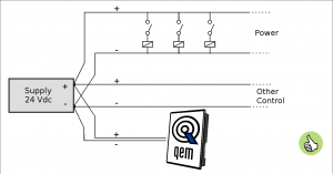
For a single power unit, use two separate lines: one for the control and one for the power 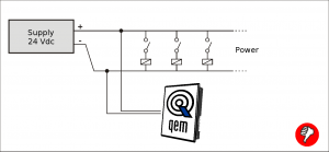
DO NOT use the same lines for the power circuit and the controller 4.2 Serial connections
CN2 Terminal RS232 RS422 RS485 Description 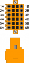
1A - - A Terminal A - RS485 2A - - B Terminal B - RS485 3A 0V 0V 0V USER PORT common 4A 0V 0V 0V USER PORT common 5A TX - - Terminal TX - RS232 6A Terra 1B - RX - Terminal RX - RS422 2B - RXN - Terminal RX N - RS422 3B - TX - Terminal TX - RS422 4B - TXN - Terminal TX N - RS422 5B RX - - Terminal RX - RS232 6B Ground Setup of USER PORT electric standard
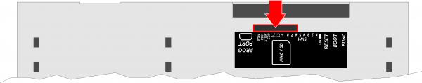
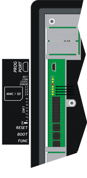
Memory card slot (marked by an arrow) 4.2.1 Serial connection features
The USB mini-B connector does not support USB electrical standards, it can only be used with an interface IQ009 or IQ013. It is used for the transfer and debugging of the application program in the CPU.
Electrical standard TTL (Use serial interface IQ009 or IQ013) Communication speed Min. 9.6 Kbaud - max 115200 Kbaud
settable by dip1 and 2 of the switch SW1Insulation None .

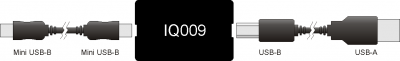

Connection between Qmove+ e PC using the accessory IQ009 .
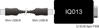
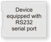
Connection between Qmove+ and a device fitted with a RS232 serial port (e.g. a MODEM), using the interface IQ013 Communication speed 4800, 9600, 19200, 38400, 57600, 115200 baud Communication mode Full duplex Operating mode Referred to 0V Max. number of devices connected on the line 1 Max. cable length 15 m Input impedence > 3 Kohm Short-circuit current limit 7 mA 

Communication speed 4800, 9600, 19200, 38400, 57600, 115200 baud Communication mode Full duplex Operating mode Differential Max. number of devices connected on the line 1 Max. cable length 1200 m Input impedence > 12 Kohm Short-circuit current limit 35 mA 


To activate the internal termination resistance see paragraph Setup of USER PORT electric standard, Setup of AUX1 PORT electric standard or Setup of AUX2 PORT polarization and termination resistances .
Communication speed 4800 baud (only if used with SERCOM and/or MODBUS device),
9600 baud, 19200 baud, 38400 baud, 57600 baudCommunication mode Half duplex Operating mode Differential Max. number of devices connected on the line 32 Max. cable length 1200 m Input impedence > 12 Kohm Short-circuit current limit 35 mA 

Type of Memory Card to use MMC, SD and SDHC up to 8GB
For proper operation it is necessary that the device conforms to the standards set by “SD Association” (www.sdcard.org) or “Multi Media Card Association” (www.mmca.org)..
To use the Memory Cards they must first be formatted with FAT16 or FAT32 file system. 4.3 Specialization card
4.3.1 Digital inputs
4.3.1.1 16 digital inputs and 2 counter inputs
CN11 Terminal Simbol Description Address 
1 - Not used 2 - Not used 3 0V Common of digital inputs 4 I1 Input I1 3.INP01 5 I2 Input I2 3.INP02 6 I3 Input I3 3.INP03 7 I4 Input I4 3.INP04 8 I5 Input I5 3.INP05 9 I6 Input I6 3.INP06 10 I7/PHA1 Input I7 or A phase of first counter 3.INP07 11 I8/PHB1 Input I8 or B phase of first counter 3.INP08 12 0V Common of digital inputs CN12 Terminal Simbol Description Address 1 - Not used 2 - Not used 3 0V Common of digital inputs 4 I9 Input I9 3.INP09 5 I10 Input I10 3.INP10 6 I11 Input I11 3.INP11 7 I12 Input I12 3.INP12 8 I13 Input I13 3.INP13 9 I14 Input I14 3.INP14 10 I15/PHA2 Input I15 or A phase of second counter 3.INP15 11 I16/PHB2 Input I16 or B phase of second counter 3.INP16 12 0V Common of digital inputs 4.3.2 Analog inputs
The electrical features are given in paragraph Electrical features.
The wiring examples are given in paragraph Connection examplesCN17 Terminal Symbol Description Address 
1 GAI Common for analog inputs 2 IA1 Analog input 1 3.AI01 3 SEL1V Analog input 1 selector, voltmetric 0-10V 1) 4 SEL1C Analog input 1 selector, amperometric 0-20mA 2) 5 GAI Common for analog inputs 6 IA2 Analog input 2 3.AI02 7 SEL2V Analog input 2 selector, 0-10V voltmetrico 3) 8 SEL2C Analog input 2 selector, 0-20mA amperometric 4) 9 VREF Reference voltage 4.3.3 Digital outputs
CN15 Terminal Symbol Description Address 
1 V+ Outputs power in (12-28Vdc) 2 O1 Digital output 1 3.OUT01 3 O2 Digital output 2 3.OUT02 4 N.C. 5 O3 Digital output 3 3.OUT03 6 O4 Digital output 4 3.OUT04 7 V- Outputs power in (12-28Vdc) 8 O5 Digital output 5 3.OUT05 9 O6 Digital output 6 3.OUT06 10 O7 Digital output 7 3.OUT07 11 O8 Digital output 8 3.OUT08 4.4 Electrical features
The following are the electrical hardware features.
Maximum and minimum frequency values and actual acquisition times, can still depend on any additional software filters, see for example the system variable “QMOVE:sys004” in the section System variables.Type of polarisation PNP Min. acquisition time (hardware) 3ms Isolation 1000Vrms Rated operating voltage 24Vdc Voltage of logic state 0 0-2 V Voltage of logic state 1 10.5 - 26.5 V Internal voltage drop 5V Input resistance (Ri) 2700Ω Sink current 2mA ÷ 8mA1)
1) CAUTION: If the device connected to the inputs needs a higher minimum current, inputs may not work properly.
Type of connection Potentiometric 1KΩ-20KΩ Resolution 12bit/16bit Reference voltage output 2.5Vdc Max output current from reference 10mA Input resistance 10MΩ Max. linearity error + 0,1% Vfs Max. offset error + 0,1% Vfs S.n. 71 dB Update speed 1ms Insulation 1000 Vrms 
Type of connection Voltmetric
0-10VResolution 12bit/16bit Input resistance (Rin) 20KΩ Damage value 20V Max. linearity error + 0.1% Vfs Max. offset error + 0.1% Vfs S.n. 71 dB Update speed 1ms Insulation 1000 Vrms 
Type of connection Amperometric
(0-20 mA)Resolution 12bit/16bit Input resistance 125Ω Damage value 25 mA Max. linearity error + 0,1% Vfs Max. offset error + 0,1% Vfs S.n. 71 dB Update speed 1ms Insulation 1000 Vrms 
Switchable load Dc (PNP) Max. operating voltage 28V Insulation 1000Vpp Max. internal voltage drop 600mV Max internal resistance @ON 90mΩ Max. protection current 12A Max. operating current 2A Max. current @OFF 5µA Max switching time from ON to OFF 270µs Max switching time from OFF to ON 250µs 
5. Connection examples
5.1 Digital inputs with encoder

5.2 Voltmetric and amperometric analog inputs

5.3 Voltmetric and potentiometric analog inputs

5.4 Protected digital outputs

6. Settings, procedures and reports

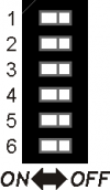
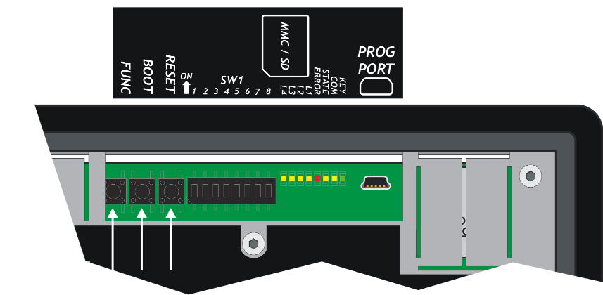
6.1 PROG PORT and USER PORT baud-rate selector
SW1 Dip DIP Setting Function 
1 OFF OFF ON ON PROG PORT transmission speed selection 2 OFF ON OFF ON Baud-rate
38400Baud-rate
115200Baud-rate
19200Baud-rate
576003 OFF OFF ON ON USER PORT transmission speed selection 4 OFF ON OFF ON Baud-rate
38400Baud-rate
115200Baud-rate
19200Baud-rate
576005 Not used 6 Not used 7 Not used 8 OFF ON Select the USER PORT as PROG PORT (the USER PORT can be used as PROG PORT with RS232 electric standard, setting to OFF the dip 6 of SW2). PROG PORT normal PROG PORT on the connector of the USER PORT 6.2 Leds
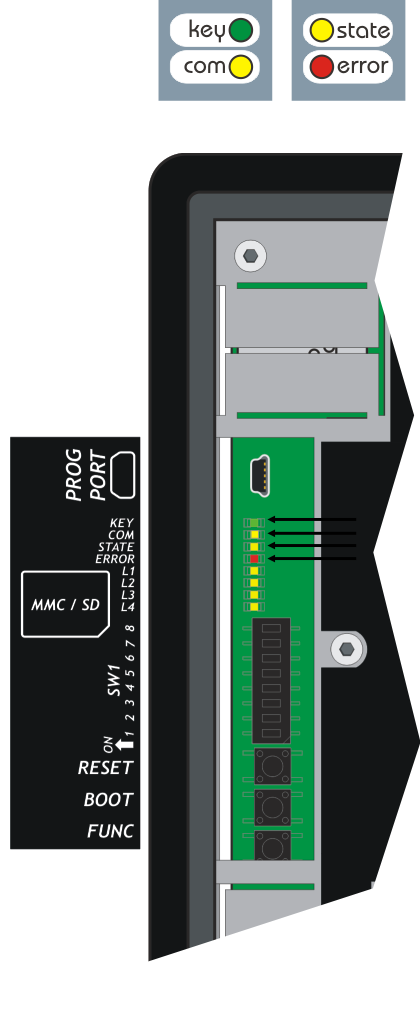
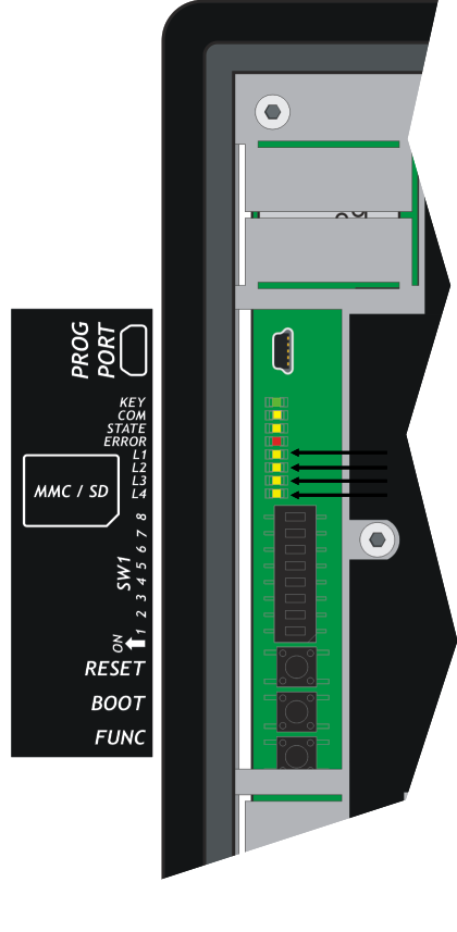
The “key, com, state, error” leds re called system led, they are found on both the front panel and on the back of HMI.

The user “L1, L2, L3 and L4” leds they are found only on the front panel:
6.2.1 Alerts "System Led"
6.2.1.1 Legend:
 Led ON
 Led OFF
 Led Flashing
Led Color State Description key Green 
Always on. Turns off when at least one key is pressed. com Green If on, indicates that the connection between the Terminal and QMOVE is not active.
The causes:
no connection between the devices;
mismatch of checksums between the Terminal and QMOVE applications;
interference on the serial line.
When the communication is restored, the led turns off.state Yellow 
If an abnormality occurs during communication between the Terminal and the QMOVE, led blinking with a 2Hz frequency. The malfunction can be hardware source (missed connection, noisy line) or software errors (incorrect readings of QMOVE variables).
The causes:
Time-Out when the terminal does not receive the response from the QMOVE.
No match when QMOVE application checksums are different from the file symbols used to build your application on the Terminal.
Read error when the read requests are made to variables with index and that index is outside of the allowed values.
Write error same for read error but for write operations.
Backup error when the data backup command of the QMOVE is not successful
Restore error when the command to restore data of thr QMOVE is not successful or when is given a command restore application and had not been previously backed up.
When the status led is flashing you should check what was the error that produced it; This can be done by accessing the Info page of the SETUP to 'Com Status' command. The error and then the blinking is cleared only on shutdown or after you exit the SETUP.error Red This led is on when it detects hardware problems that might lead to malfunction of the system. Contact the QEM. 6.2.2 Alerts “User Led”
Led Color Description L1Yellow Delete application L2Delete the application from the MMC/SD.
The file must be named as: appqtp.bin L1 L2Execute the calibration of the Touch Screen. L3No function L4No function 6.3 Keys
Name Description  FUNC
FUNCPressed enters or exit from the system functions BOOTPressed execute the selected function RESETNo function 7. General information of operation
7.1 Introduction
This chapter will introduce some concepts and describes some operations of the product. These contents are partly related and implemented in firmware. This software implements all features that allow the product to be a component of the system programmable Qmove.
7.2 Organizing data and memories
To best understand the terms used in this chapter, it is important to know the organisation of data and memory in a QMOVE application. QMOVE applications are programs written in QCL language that, translated in binary code, are transferred onto QMOVE hardware and saved there. In the hardware, the microprocessor runs has a program called firmware that interprets the above binary code instructions and performs the operations associated to them.
A QCL application, in addition to the instructions, is also composed of variables that the QCL instructions act on.. Some of these variables are retentive, i.e. their values remain unaltered from shut-off to start up. The flow chart below illustrates the organisation of data in a QCL application transferred to the memory of any QMOVE hardware:
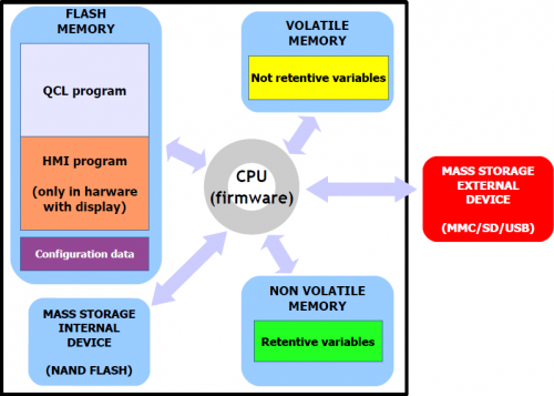
It can be noted that, the QMOVE hardware has several mass storage devices:
“Flash memory”, where the following is saved:
-
QCL program: the series of QCL instructions translated into binary by the compiler.
-
HMI program: the series of HMI screens translated into binary by the compiler. This program only exists when the QMOVE hardware has a display.
-
Configuration data: the calibration and configuration data, the touch-screen calibration settings, the ethernet communication configuration data (IP address, etc…), etc.
“Non volatile memory”, which stores:
-
Retentive variables: the group of variables that remains unaltered on a shut-off and startup (e.g. SYSTEM, ARRAYS, DATAGROUP, etc).
“Volatile memory”, which stores:
-
Not retentive variables: the group of variables that is set to 0 at each startup (e.g. GLOBAL, ARRGBL, etc).
The volatile data memory is also used as dynamic memory. i.e. the memory used by the firmware for internal operations and active HMI screen management.
“Mass storage internal device” is managed by a standard filesystem and is useful to save information by the DATASTORE device (read - write binary or csv files with recipes, logs, variuous setups, etc).
It 'also used to store the backup of the application QMOVE and other service files.“Mass storage external device” is managed by a standard filesystem and is useful for loading the QMOVE application, data loading/saving, firmware update or to save informations by the DATASTORE device.
7.3 SETUP PAGE
ATTENZIONE: WARNING: The use of these procedures is potentially dangerous (see for example the application delete) and it is preferable that is carried out by a specialist supervision. The system functions are special procedures that allow the user to perform various operations such as setting/calibration of devices, saving/restoring data and application on/from removable devices, deleting the application and management of storage devices.
To access the new system functions simply login to instrument SETUP.Note: If there is no Terminal application software will automatically enter in SETUP.
7.3.1 Procedure
To access in the System functions, press the BOOT key or press together the keys “F2 + F4 + F6”. 


BOOTThe following menu appears:
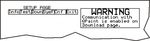
To select a function using the vertical arrows of the virtual keyboard, then press Enter
 for view the selected function.
The system restarts and displays the system function selected.
for view the selected function.
The system restarts and displays the system function selected.
Virtual keyboard 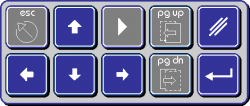
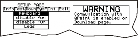
7.3.2 Setup page menu
Lists and describes all system functions.
7.3.2.1 Navigation keys
To enter/confirm the functions press ENTER key
.
The UP and DW
  keys perform changes of values.
To switch from one page to another press PAGE DOWN key or PAGE UP key
  .
.
For exit from the menu press the ESC key .
.
Note: For exit from the system functions select
“EXIT”from the main menu.7.3.2.2 Info menu
7.3.2.2.1 INFO PAGE 1/6
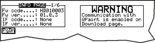
7.3.2.2.2 FW code
Firmware code (es. HD010003)
7.3.2.2.3 FW ver.
Firmware version (es. 01.0.3)
7.3.2.2.4 IF code
Data not available.
7.3.2.2.5 IF ver.
Data not available.
7.3.2.2.6 INFO PAGE 2/6
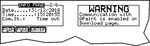
7.3.2.2.7 Date
System date.
The ESC key is inhibited until the confirmation of all the fields by pressing the ENTER key.
7.3.2.2.8 Time
System clock.
The ESC key is inhibited until the confirmation of all the fields by pressing the ENTER key.
7.3.2.2.9 Com.St.
Reports the status of the serial communication. If everything is OK the message:
Ok
If the ‘COM’ led is ON and the'STATE' led flashing, the connection between the HMI and the QMOVE is not active. The reasons can be:Checksum wrong Appears the ‘No match’ message, which means that the application built for the Terminal is not compatible with the QMOVE software and then the communication is not established because it may create incompatibilities in data of the system. The ‘No match’ condition excludes communication problems due to connection errors or problems related to serial ports.
Communication interrupted Appears the ‘Time Out’ message, which means that the terminal not received response or the response has not been received completely. If the ‘COM’ led is ON it probably means there is a malfunction of one of the two devices (QMOVE or HMI) or connection between the device. If the 'COM' led is OFF means that at least one ‘Time Out’ occured from the power ON (example an electrical noise).
Reading errors Appears the ‘Read Error’ message, which means that the the response string to a reading didn't the correct syntax of the Protocol. This can happen if the Terminal makes a request of a variable with index out of range. For example the read request of an element of an array, where the value of i is greater than the size of the array itself; if i is a constant value that the compiler of the application can inspect and report the error, but if i is the value that is contained in a variable can take place such an error.
Writing errors Appears the ‘Write Error’ message, which means that the response string to a reading didn't the correct syntax laid down in the Protocol. All that has been described for the readings also applies to torn writes
Backup error Appears the ‘Backup Error’ message, which means that the QMOVE application data backup operation is not successful.
Restore error Appears the ‘Restore Error’ message, which means that the restore operation of data of the QMOVE application is not successful.
7.3.2.2.10 INFO PAGE 3/6
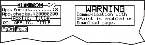
7.3.2.2.11 App.format
Identifies the type of application file format. It is used to prevent the execution of applications with a format that is not compatible with the firmware. (Is an information used only by the development “QPaint” software).
7.3.2.2.12 App.checks
The value allows you to uniquely identify a particular application. It is computed on the information used in the download of the application.
7.3.2.2.13 App.title
Is a string that is set in the configuration “Qpaint” program to identify the application. Cannot be changed.
7.3.2.2.14 INFO PAGE 4/6
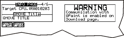
7.3.2.2.15 Target CPU
You see the CPU type connected with the Terminal. This information is detected with a reading from the Qmove CPU.
7.3.2.2.16 Qmove Title
Is the application title exists in the Qmove CPU. This information is detected with a serial reading by Qmove CPU.
7.3.2.2.17 INFO PAGE 5/6
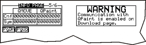
7.3.2.2.18 Checksum table
You see the checksum file configuration and application Qmove symbols and symbols which the application has been generated. The first is read with the serial from the CPU, the second is a value contained in the data download.
If the checksum do no match, the connection isn't enabled between the Terminal and Qmove variables. (see “no match error or incorrect Checksum” ).7.3.2.2.19 INFO PAGE 6/6
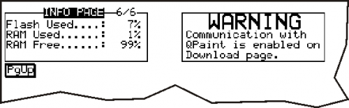
7.3.2.2.20 Flash Used
The value refers to the space occupied in the flash memory of QPaint project. The value is the same to the one displayed on the download page.
7.3.2.2.21 RAM Used
The value refers to the space occupied in the RAM memory from the current page displayed by the terminal before logging on to the Setup. The value refers to all structures allocated to run the page.
7.3.2.2.22 RAM Free
The value refers to the free space of the RAM memory. The sum of the first and third value, indicates the total RAM memory space.
7.3.2.3 Test Menu
The HMI has the following test procedures to assist the operator:
7.3.2.3.1 Keyboard
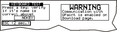
At the pressure of any button you see the message.
For exit press and hold the “ESC” key for 2 sec.
7.3.2.3.2 Leds
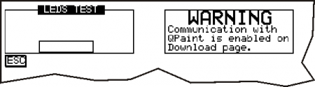
The function key leds are activated in succession with variable frequency.
Don't execute the system leds test (“Key”, “Com”, “State”, “Error”) because the function it isn't programmable and because their indications are not essential to the functionality.7.3.2.4 Down Menu (Download)
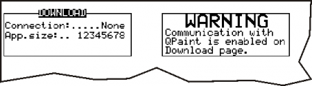
The DOWNLOAD procedure allows the Terminal to receive the information needed to run the application designed by the user. The steps performed during the download procedure are:
-
Verifying the connection
-
Flash memory delete
-
Displays the size of your application to receive
-
Software download
7.3.2.5 SysF Menu (System Functions)
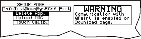
The entry in this menu is indicated by the following Leds:
Led ON Color Menù SysF description System function Description L2Yellow Delete App.Application deleteDelete the application L1 L2Upload MMCApplication upload from MMC/SDCApplication upload from MMC/SD.
The file must be named as: appqtp.bin L3Touch Calib.Touch CalibrationThe Touch Screen calibration. For the description of functions see section System functions
7.3.2.6 Cnf Menu (Configuration)
The changes will be put into execution at the exit from the configuration page.
7.3.2.6.1 Config. Page 1/2
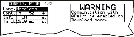
Each time you press the button ENTER
key you jump from one sector to another sector.
Lang. Is the choice of the languages to be used. This array of strings is decided at design time in the Setup program.
Cont. Is the value of the display contrast.
Info Debug informations (default = OFF).
Tm CL CLEAR key time. During the dataentry, if the CLEAR button is pressed for longer than the time set the given typed is cleared. If the CLEAR button is pressed impulsively you cancel only one digit of the given type.
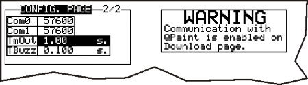
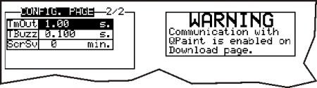
7.3.2.6.2 Config. Page 2/2
Depending on the firmware version can also exit this window:
Com0 Serial port speed System.
Com1 Serial port speed AUX.
TmOut Timeout on request to the CPU (default = 1.00 s).
TBuzz Operating time of the buzz when press a button (default = 0.100 s).
ScrSv Screen-saver settings:
0 = disable (default). Display always on.
1..60 = switches off the display after pressing the buttons or touch after 1..60 minutes. Press any key or touch the display for resumes.7.3.3 System functions
7.3.3.1 Delete App. function
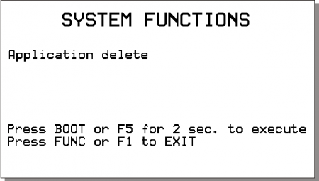
Press the BOOT key/F5 key for 2 seconds the the selected function is executed. 
BOOTThe POW led starts flashing to indicate that the selected function is running. POWWhen the function ends the POW led stops flashing.  POW
POWPress the FUNC key/F1 key to exit from the function 
FUNC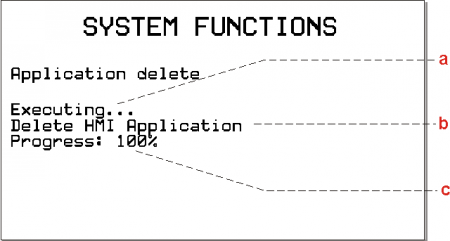
-
a = indicates that the function is in running.
-
b = task running.
-
c = percentage of the function executed.
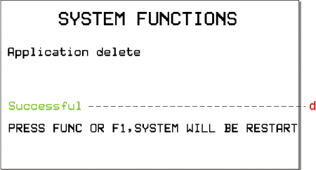
-
d = indicates that the function was successful.
7.3.3.2 Upload MMC function
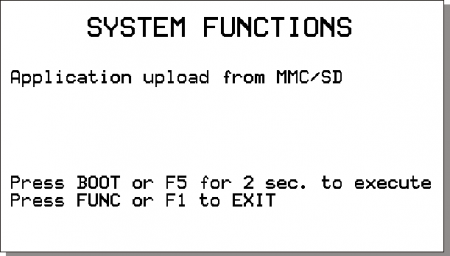
Press the BOOT key/F5 key for 2 seconds the selected function is executed.
BOOTThe POW led starts flashing to indicate that the selected function is running. POWWhen the function ends the POW led stops flashing. POWPress the FUNC key/F1 key to exit from the function
FUNC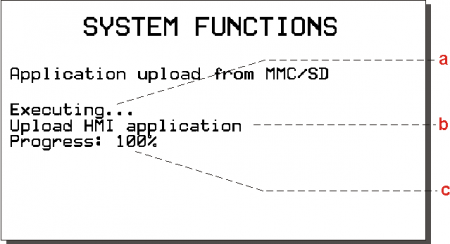
-
a = indicates that the system is running.
-
b = operation running.
-
c = percentage of function executed.
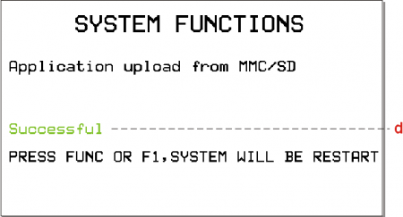
-
d = indicates that the function was successful.
Press the FUNC key/F1 key the instrument restars.
FUNCf the function is not successful POW led turns OFF and start the ERR led. POW
ERR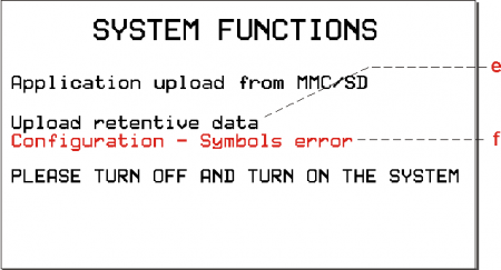
-
e = operation that caused the error.
-
f = indicates the type of error occurred.
The number of flashes indicates the type of error occurred as shown in table Error messages of system functions.
7.3.3.3 Touch Calib. function
This procedure, only available on instruments with touch-screen. Need to calibrate the pointing device.
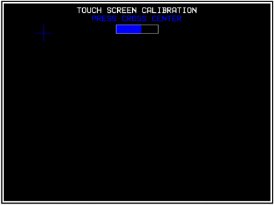
At the entrance of the procedure, is presented with a screen that has a blue cross.
Press the center of the cross until the progress bar has reached completion.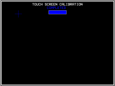
Appears the “COMPLETED”message and and you can release the pressure.
Note: If the pressure is released before completion of the progress bar, the procedure is aborted and the“!! OPERATION ABORTED !!”message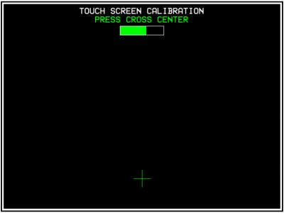
Thereupon a new Green Cross. Even in this case, repeat until the progress bar is complete and is displayed “COMPLETED”message.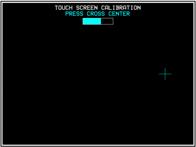
It then proposed a final page with a new cyan colored cross. Even in this case, repeat until the progress bar is complete and is displayed “COMPLETED”message.7.3.3.4 Error messages of system functions
When a system function ends with an error displays a message that describes the cause of the error.
Error/Flashing number ERR led Message 1 Generic error2 Open/Exist/Create file error3 Read file error4 Write file error5 Out of Memory error6 QMos Version error7 Checksum Error8 Symbols checksum No Match9 Configuration / Symbols error10 File format error11 Format error12 Device not present or unformatted13 Application not present error14 Touch operation failure15 File compression type not support16 Target don't match project !17 Fw version don't match project !18 File copy error19 Function not enabled7.4 Information for programming
In this section are collected all the product information you need while you are programming, or during development of an application QCL.
7.4.1 Development softwares
For programming the product you should use the Qview-5 for QCL and Qpaint-5 for the design of graphics pages. Both of these software are contained in a software package called Qworkbench and it is freely downloadable from the site Qem (in the download section).
For programming with the development software QPaint-5 it is important select the correctly the target. Select Project → Target Configuration ans select the correctly model.
This paragraph looks at how to measure an estimate of use of the product's memories. The nonvolatile memory is available to memorise the QCL program and has a capacity of 512KB.
The memory space occupied is equal to the size of the .BIN file generated by Qview. The percentage memory occupied can be viewed in the CPU panel of Qview under “Used CODE memory”, or this information can be obtained from the value of parameter “sizeapp” of the QMOS device.The nonvolatile memory available to memorise the HMI program has a capacity of 5.5MB.
The memory space occupied is equal to the size of the .BIN file generated by Qpaint, whose value (in bytes) is viewed in parameter “memqtp” of the MMIQ2 device.The nonvolatile data memory used to memorise retentive variables, has a capacity of 819KB.
The percentage memory occupied can be viewed in the CPU panel of Qview, under “Used RETENTIVE”, or this information can be obtained from the value of parameter “sizeret” of the QMOS device.The volatile data memory used to memorise non ritentive variables has a capacity that depends on various factors (e.g. the HMI and QCL program sizes, the HMI screen being viewed, etc)
The general memory of the free system, available as volatile data memory, is indicated by parameter “memfree” in the MMIQ2 device.8. Available accessories
-
-


- Last modified: 2022/11/22 09:30